1995 NISSAN ALMERA N15 hood release
[x] Cancel search: hood releasePage 1224 of 1701
ENGINEREMOVAL
WARNING:
a. Situate vehicle onaflat and solid surface.
b. Place chocks atfront andback ofrear wheels.
c. Donot remove engineuntilexhaust systemhascompletely
cooled off.
Otherwise, youmay burn yourself and/orfiremay break out
in fuel line.
d. For safety during subsequent steps,thetension ofwires
should beslackened againsttheengine.
e. Before disconnecting fuelhose, release fuelpressure from
fuel line.
Refer to"Releasing FuelPressure" inEC section.
f. Besure tohoist engine andtransaxle inasafe manner.
g. For engines notequipped withengine slingers, attach
proper slingers andbolts described inPARTS CATALOG.
CAUTION:
• When liftingengine, besure toclear surrounding parts.
Take special careforaccelerator wirecasing, brakelines
and brake master cylinder.
• Inhoisting theengine, alwaysuseengine slingers inasafe
manner.
• Inremoving driveshaft, becareful nottodamage grease
seal oftransaxle.
Engine cannotberemoved separately fromtransaxle. Remove
engine withtransaxle.
Removal
1. Drain water.
2. Remove hood.
3. Remove battery.
4. Remove reservoir tankandbracket.
5. Remove drivebelts.
6. Remove alternator, compressor andpower steering oil
pump fromengine.
Power steering pumpdoesnotneed tobe disconnected from
power steering tubes.
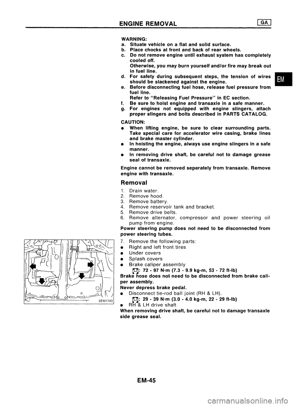
7. Remove thefollowing parts:
• Right andleftfront tires
• Under covers
• Splash covers
• Brake caliper assembly
~: 72-97 N'm (7.3•9.9 kg-m, 53•72 ft-Ib)
Brake hosedoes notneed tobe disconnected frombrake cali-
per assembly.
Never depress brakepedal.
• Disconnect tie-rodballjoint (RH
&
LH).
~: 29-39 N'm (3.0-4.0 kg-m, 22-29 ft-Ib)
• RH
&
LH drive shaft
When removing driveshaft, becareful nottodamage transaxle
side grease seal.
EM-45
•
Page 1278 of 1701
SEM092DENGINE
REMOVAL
WARNING:
• Situate vehicle onaflat and solid surface.
• Place chocks atfront andback ofrear wheels.
• Donot remove engineuntilexhaust systemhascompletely
cooled off.
Otherwise, youmay burn yourself and/orfiremay break out
in fuel line.
• For safety during subsequent steps,thetension ofwires
should beslackened againsttheengine.
• Before disconnecting fuelhose, release fuelpressure from
fuel line.
Refer to"Releasing FuelPressure" inEC section.
• Besure tohoist engine andtransaxle inasafe manner.
• For engines notequipped withengine slingers, attach
proper slingers andbolts described inPARTS CATALOG.
CAUTION:
• When liftingengine, becareful nottostrike adjacent parts,
especially thefollowing: Accelerator wirecasing, brake
lines, andbrake master cylinder.
• Inhoisting theengine, alwaysuseengine slingers inasafe
manner.
Removal
1. Remove engineundercoverandhood.
2. Drain coolant frombothcylinder block,andradiator.
3. Drain engine oilfrom drain plugofoil pan.
4. Remove vacuumhoses,fuelhoses, wires,harness andcon-
nectors andsoon.
5. Remove exhausttubes,balljoints anddrive shafts.
6. Remove radiatorandfans.
7. Remove drivebelts.
8. Remove alternator, compressor andpower steering oil
pump fromengine.
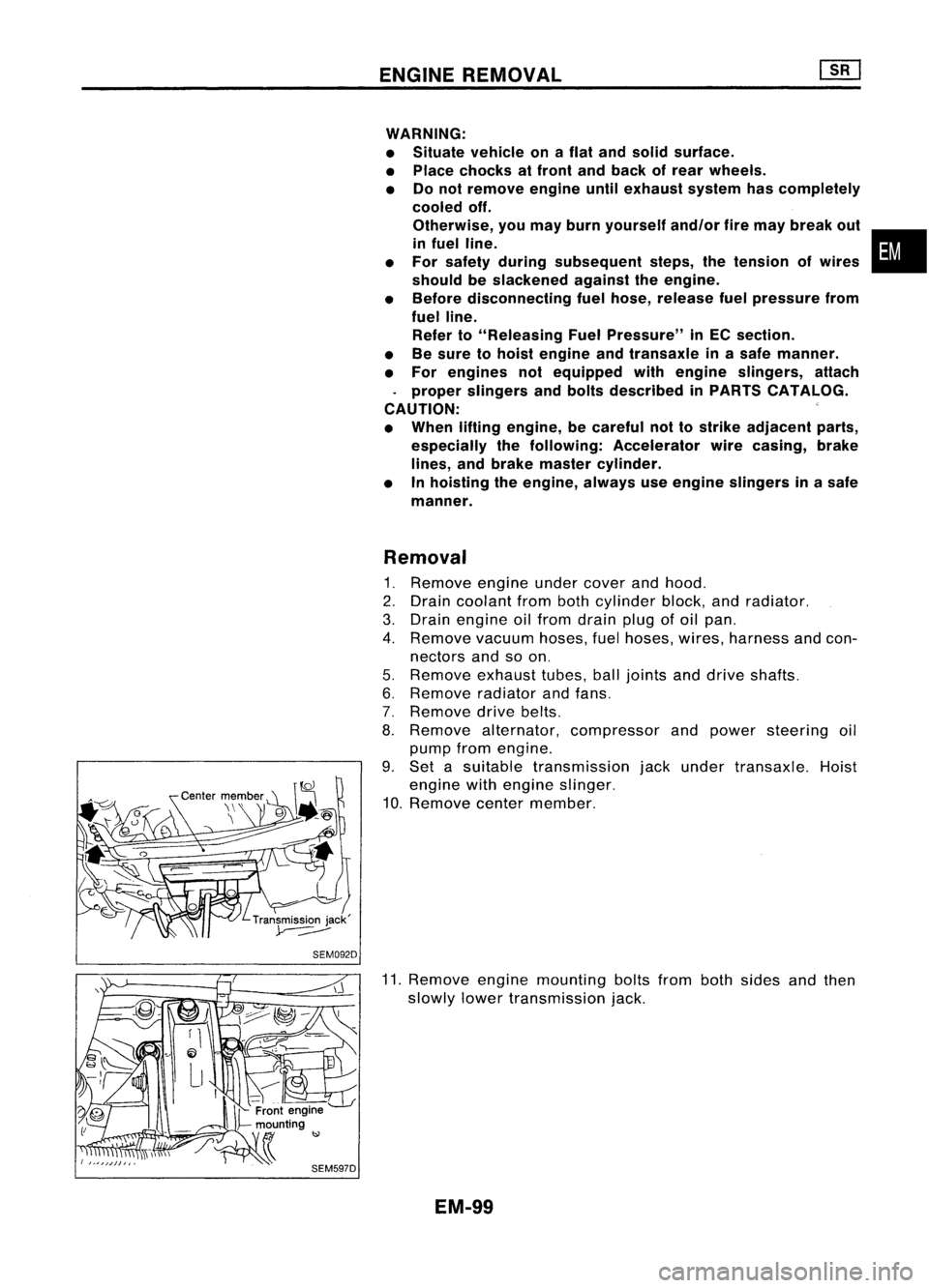
9. Set asuitable transmission jackunder transaxle. Hoist
engine withengine slinger.
10. Remove centermember.
11. Remove enginemounting boltsfrombothsides andthen
slowly lowertransmission jack.
EM-99
•
Page 1368 of 1701
Normallyopen
HOW
TOREAD WIRING DIAGRAMS
Description (Cont'd)
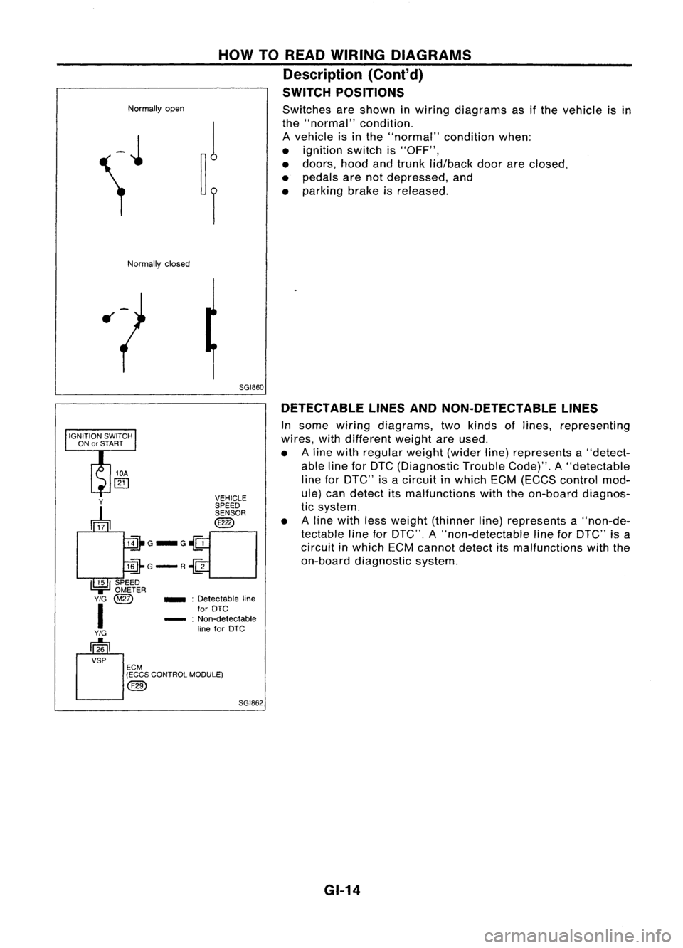
SWITCH POSITIONS
Switches areshown inwiring diagrams asifthe vehicle isin
the "normal" condition.
A vehicle isin the "normal" conditionwhen:
• ignition switchis"OFF",
• doors, hoodandtrunk lid/back doorareclosed,
• pedals arenotdepressed, and
• parking brakeisreleased.
Normally closed
5GI860DETECTABLE LINESANDNON-DETECTABLE LINES
In some wiring diagrams, twokinds oflines, representing
wires, withdifferent weightareused.
• Aline with regular weight(widerline)represents a"detect-
able lineforDTC (Diagnostic TroubleCode)".A"detectable
line forDTC" isacircuit inwhich ECM(ECCS control mod-
ule) candetect itsmalfunctions withtheon-board diagnos-
tic system.
• Aline with lessweight (thinner line)represents a"non-de-
tectable lineforDTC", A"non-detectable lineforDTC" isa
circuit inwhich ECMcannot detectitsmalfunctions withthe
on-board diagnostic system.
SGI862
_
:Detectable line
for DTC
- :Non-detectable
line forDTC
Y
~ VEHICLE
SPEED SENSOR
@
lill-G_G~
llli-G-R~
I~I
SPEED
.,=
OMETER
Y/G
@Z)
I
Y/G
[]26
VSP ECM
(ECCS CONTROL MODULE)
@)
GI-14
Page 1492 of 1701
GENERALMAINTENANCE
General maintenance includesthoseitemswhich should bechecked duringthenormal day-to-day
operation ofthe vehicle. Theyareessential ifthe vehicle isto continue operating properly.Theowners
can perform thechecks andinspections themselves orthey canhave theirNISSAN dealersdothem.
Item
OUTSIDE THEVEHICLE
The maintenance itemslistedhereshould beperformed fromtimetotime, unless oth-
erwise specified.
Tires
Check thepressure withagauge periodically whenataservice station, including
the spare, andadjust tothe specified pressureifnecessary. Checkcarefully fordamage,
cuts orexcessive wear.
Windshield wiperblades
Checkforcracks orwear ifthey donot wipe properly.
Doors andengine hood
Check thatalldoors, theengine hood,thetrunk lidand back
door operate properly. Alsoensure thatalllatches locksecurely. Lubricate hinges,
latches, rollersandlinks ifnecessary. Makesurethatthesecondary latchkeeps thehood
from opening whentheprimary latchisreleased.
When driving inareas usingroadsaltorother corrosive materials, checkforlubrication
frequently.
Tire rotation
Tiresshould berotated every
10,000
km
(6,000
miles).
INSIDE THEVEHICLE
The maintenance itemslistedhereshould bechecked onaregular basis,suchaswhen
performing periodicmaintenance, cleaningthevehicle, etc.
Lights
Makesurethattheheadlights, stoplights, taillights, turnsignal lights,andother
lights arealloperating properlyandinstalled securely. Alsocheck headlight aim.
Warning lightsandbuzzers/chimes
Makesurethatallwarning lightsandbuzzers/chimes
are operating properly.
Steering wheel
Check forchange inthe steering conditions, suchasexcessive freeplay,
hard steering orstrange noises.
Free play: Lessthan35mm (1.38 in)
Seat belts
Check thatallparts ofthe seat beltsystem (e.g.buckles, anchors, adjusters
and retractors) operateproperly andsmoothly, andareinstalled securely. Checkthebelt
webbing forcuts, fraying, wearordamage.
UNDER THEHOOD ANDVEHICLE
The maintenance itemslisted hereshould bechecked periodically e.g.each timeyou
check theengine oilorrefuel.
Windshield washerfluid
Check thatthere isadequate fluidinthe tank.
Engine coolant level
Check thecoolant levelwhen theengine iscold.
Engine oillevel
Check thelevel afterparking thevehicle onalevel spotandturning off
the engine.
Brake andclutch fluidlevels
Makesurethatthebrake andclutch fluidlevels arebetween
the "MAX" and"MIN" linesonthe reservoir.
Battery
Checkthefluid level ineach cell.Itshould bebetween the"MAX" and"MIN"
lines.
MA-6
Reference
pages
MA-51
MA-50
MA-19,38
MA-24, 33,41
MA-45,47
Page 1537 of 1701
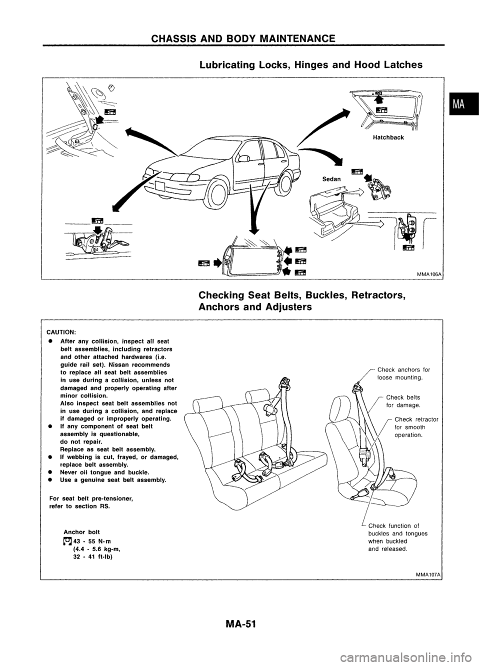
CHASSISANDBODY MAINTENANCE
lubricating locks,Hinges andHood latches
•
MMA106A
Hatchback
/
"
m
S.d" ~
__ m__
~
CheckingSeatBelts, Buckles, Retractors,
Anchors andAdjusters
CAUTION: • After anycollision, inspectallseat
belt assemblies, includingretractors
and other attached hardwares (i.e.
guide railset). Nissan recommends
to replace allseat beltassemblies
in use during acollision, unlessnot
damaged andproperly operating after
minor collision.
Also inspect seatbeltassemblies not
in use during acollision, andreplace
if damaged orimproperly operating.
• Ifany component ofseat belt
assembly isquestionable,
do not repair.
Replace asseat beltassembly.
• If
webbing iscut, frayed, ordamaged,
replace beltassembly.
• Never oiltongue andbuckle.
• Use agenuine seatbeltassembly.
For seat beltpre.tensioner,
refer tosection RS.
Anchor bolt
tcJ
43•55 N.m
(4.4 •5.6 kg-m,
32 •41 ft.lb)
Check
anchors for
loose mounting.
Check function of
buckles andtongues
when buckled
and released.
MMA107A
MA-51