1995 NISSAN ALMERA N15 oil level
[x] Cancel search: oil levelPage 24 of 1701
TROUBLEDIAGNOSES
Stall Tasting
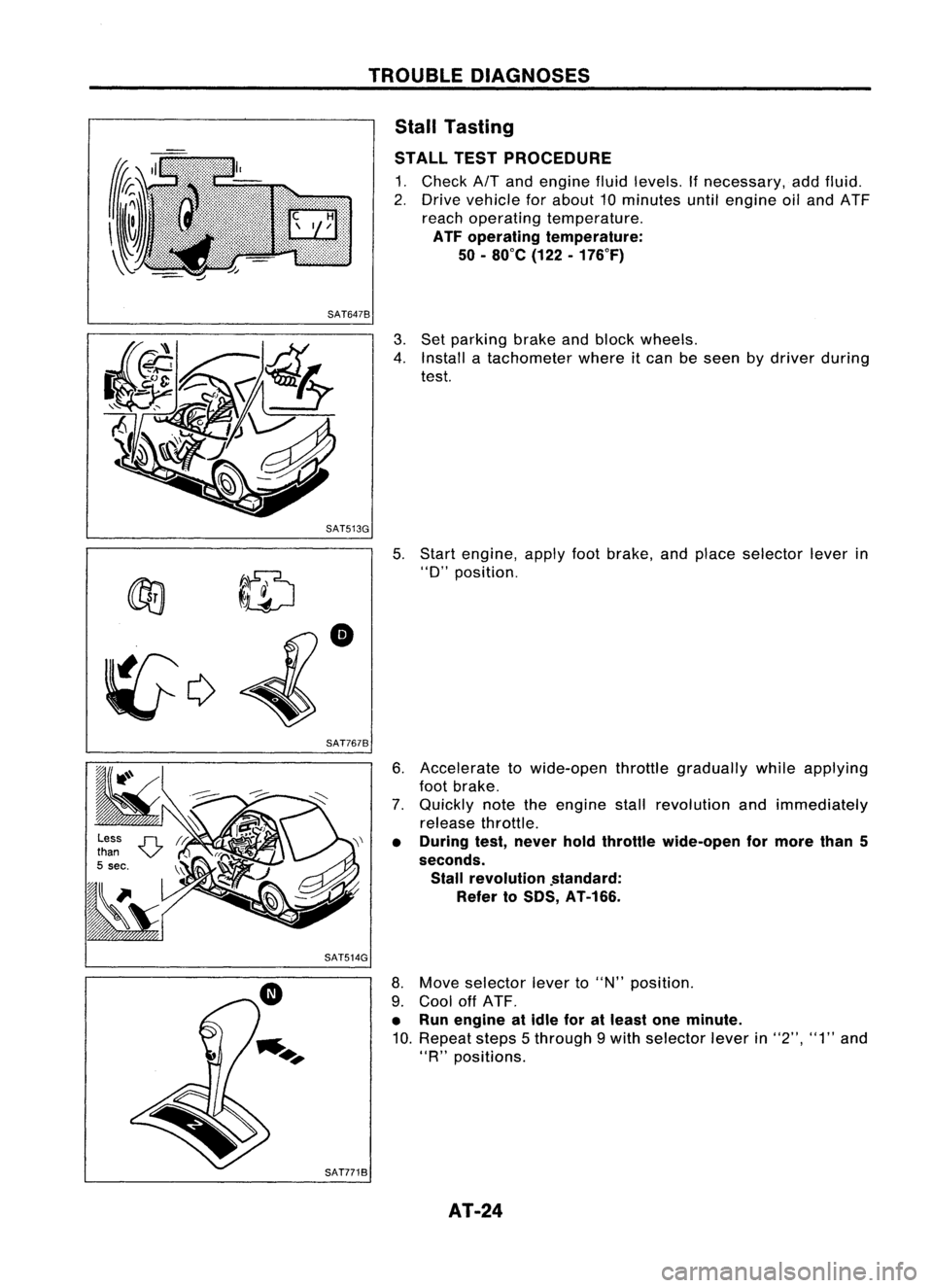
STALL TESTPROCEDURE
1. Check
AIT
and engine fluidlevels. Ifnecessary, addfluid.
2. Drive vehicle forabout 10minutes untilengine oiland ATF
reach operating temperature.
ATF operating temperature:
50 -80
0
e (122-176°F)
SAT6478
3.Set parking brakeandblock wheels.
4. Install atachometer whereitcan beseen bydriver during
test.
SAT513G 5.
~ ~ID
•
~c;>
SAT7678
Start
engine, applyfootbrake, andplace selector leverin
"0"
position.
6. Accelerate towide-open throttlegradually whileapplying
foot brake.
7. Quickly notetheengine stallrevolution andimmediately
release throttle.
• During test,never holdthrottle wide-open formore than5
seconds. Stall revolution .standard:
Refer toSDS, AT-166.
SAT514G
8.Move selector leverto"N" position.
9. Cool offATF.
• Run engine atidle foratleast oneminute.
10. Repeat steps5through 9with selector leverin"2", "1"and
"R
n
positions.
SAT7718 AT-24
Page 26 of 1701
TROUBLEDIAGNOSES
Pressure Testing
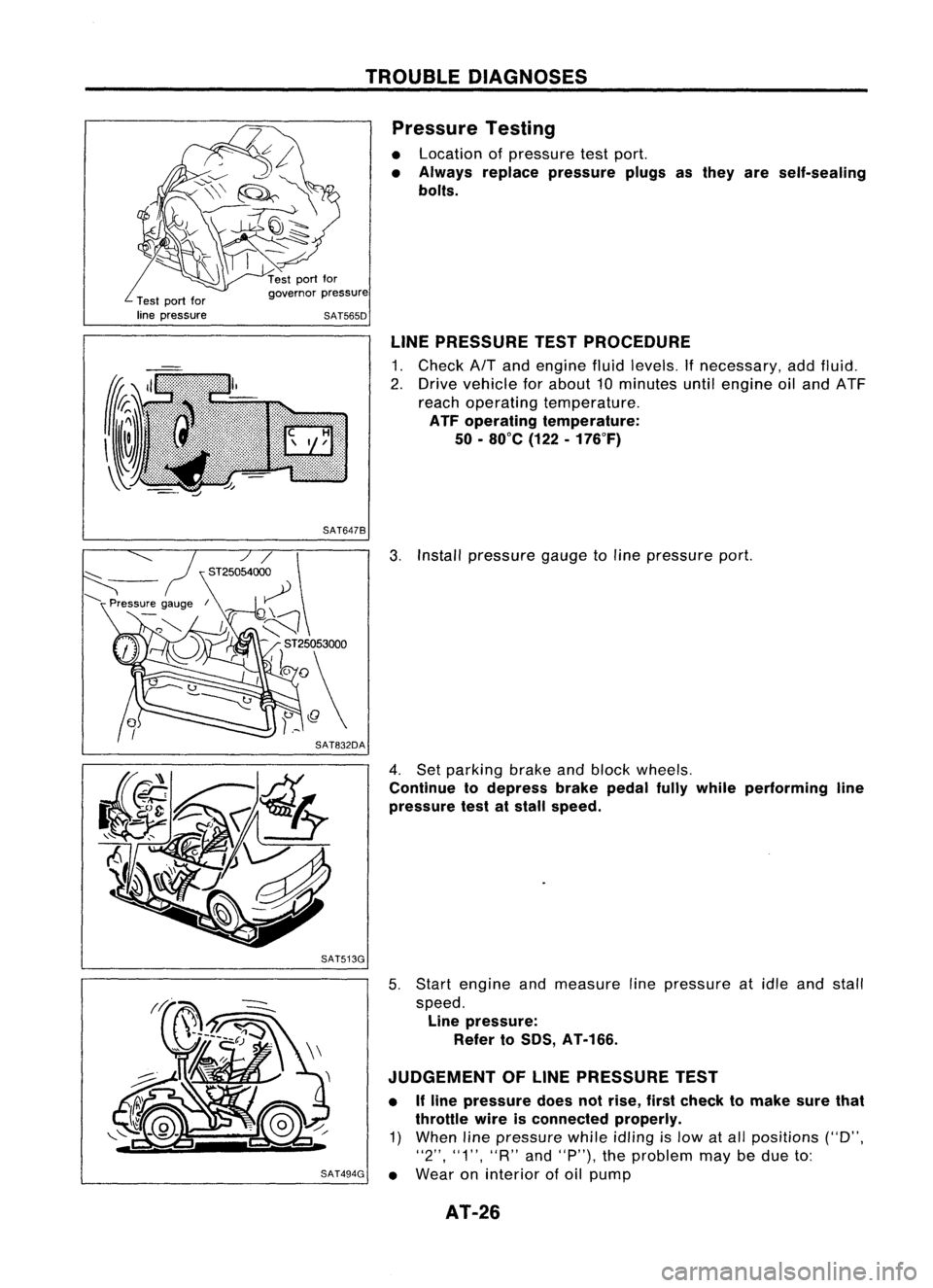
• Location ofpressure testport.
• Always replace pressure plugsasthey areself-sealing
bolts.
Test portfor
line pressure governor
pressure
SAT565D
LINEPRESSURE TESTPROCEDURE
1. Check AfTand engine fluidlevels. Ifnecessary, addfluid.
2. Drive vehicle forabout 10minutes untilengine oiland ATF
reach operating temperature.
ATF operating temperature:
50 -80°C (122-176°F)
SAT647B
3.Install pressure gaugetoline pressure port.
4. Set parking brakeandblock wheels.
Continue todepress brakepedalfullywhile performing line
pressure testatstall speed.
SAT513G
5.Start engine andmeasure linepressure atidle and stall
speed. Line pressure:
Refer toSOS, AT-166.
JUDGEMENT OFLINE PRESSURE TEST
• Ifline pressure doesnotrise, firstcheck tomake surethat
throttle wireisconnected properly.
1) When linepressure whileidling
is
low atall positions ("D",
"2", "1", "R"and"P"), theproblem maybedue to:
SAT494G •
Wear oninterior ofoil pump
AT-26
Page 27 of 1701
'-)
(
~)o
Front
SAT498GTROUBLE
DIAGNOSES
Pressure Testing(Cont'd)
• Oilleakage ator around oilpump, control valvebody, trans-
mission caseorgovernor
• Sticking pressure regulator valve
• Sticking pressure modifiervalve
2) When linepressure whileidling islow ataparticular
position, checkthefollowing.
• Ifoil leaks ator around low
&
reverse brakecircuit, line
pressure becomes lowin"R" position. Butline pressure is
normal in"P", "D", "2"or"1" position.
3) When linepressure ishigh while idling, pressure regulator
valve mayhave stuck.
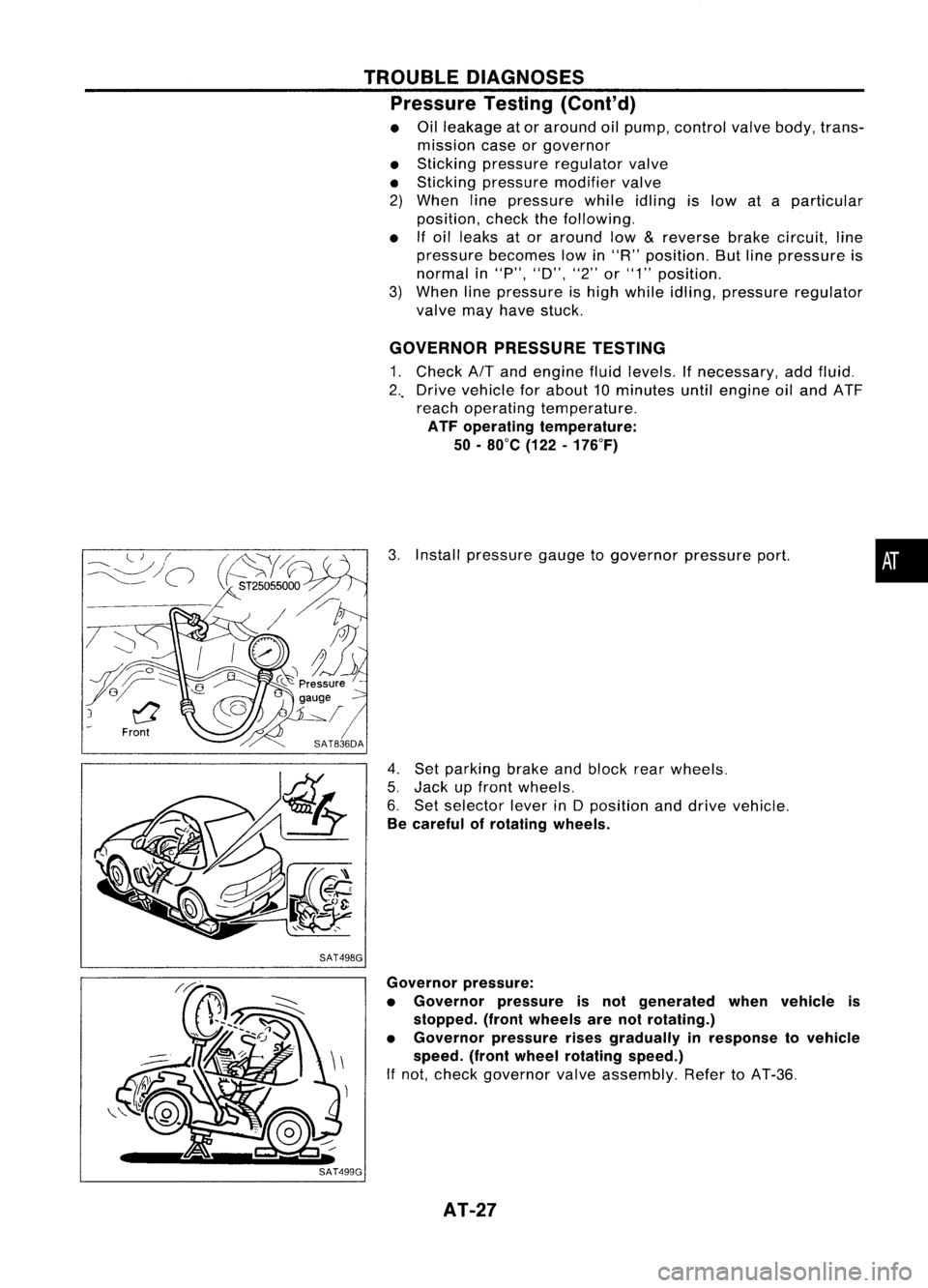
GOVERNOR PRESSURETESTING
1. Check
AIT
and engine fluidlevels. Ifnecessary, addfluid.
2 .. Drive vehicle forabout 10minutes untilengine oiland ATF
reach operating temperature.
ATF operating temperature:
50 -80°C (122-176°F)
3. Install pressure gaugetogovernor pressureport.
4. Set parking brakeandblock rearwheels.
5. Jack upfront wheels.
6. Set selector leverinDposition anddrive vehicle.
Be careful ofrotating wheels.
•
Governor pressure:
• Governor pressureisnot generated whenvehicle is
stopped. (frontwheels arenotrotating.)
• Governor pressurerisesgradually inresponse tovehicle
speed. (frontwheel rotating speed.)
If not, check governor valveassembly. RefertoAT-36.
AT-27
Page 275 of 1701
CHECKANDADJUSTMENT
OK
MINMax.
line
Min. line
SBR418C
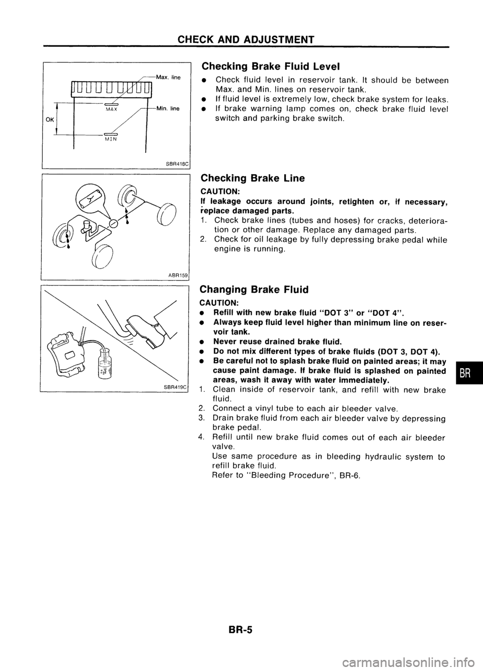
Checking
BrakeFluidLevel
• Check fluidlevel inreservoir tank.Itshould bebetween
Max. andMin. lines onreservoir tank.
• Iffluid level isextremely low,check brakesystem forleaks.
• Ifbrake warning lampcomes on,check brakefluidlevel
switch andparking brakeswitch.
ABR159
SBR419C
Checking
BrakeLine
CAUTION: If leakage occursaround joints,retighten or,ifnecessary,
replace damaged parts.
1. Check brakelines(tubes andhoses) forcracks, deteriora-
tion orother damage. Replaceanydamaged parts.
2. Check foroilleakage byfully depressing brakepedalwhile
engine isrunning.
Changing BrakeFluid
CAUTION:
• Refill withnewbrake fluid"DOT 3"or"DOT 4".
• Always keepfluidlevel higher thanminimum lineonreser-
voir tank.
• Never reusedrained brakefluid.
• Donot mix different typesofbrake fluids(DOT3,DOT 4).
• Becareful nottosplash brakefluidonpainted areas;itmay •
cause paintdamage. Ifbrake fluidissplashed onpainted :•
areas, washitaway withwater immediately.
1. Clean inside ofreservoir tank,andrefill withnewbrake
fluid.
2. Connect avinyl tubetoeach airbleeder valve.
3. Drain brake fluidfrom each airbleeder valvebydepressing
brake pedal.
4. Refill untilnewbrake fluidcomes outofeach airbleeder
valve.
Use same procedure asinbleeding hydraulic systemto
refill brake fluid.
Refer to"Bleeding Procedure", BR-6.
BR-5
Page 289 of 1701
~0
tJ
L:{SR020D
FRONT
DISCBRAKE
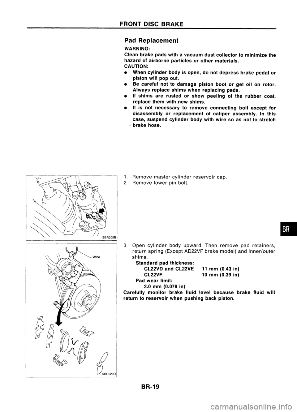
Pad Replacement
WARNING:
Clean brakepadswithavacuum dustcollector tominimize the
hazard ofairborne particles orother materials.
CAUTION:
• When cylinder bodyisopen, donot depress brakepedalor
piston willpop out.
• Becareful nottodamage pistonbootorget oilonrotor.
Always replace shimswhenreplacing pads.
• Ifshims arerusted orshow peeling ofthe rubber coat,
replace themwithnewshims.
• Itis not necessary toremove connecting boltexcept for
disassembly orreplacement ofcaliper assembly. Inthis
case, suspend cylinderbodywithwire soasnot tostretch
. brake hose.
1. Remove mastercylinder reservoir cap.
2. Remove lowerpinbolt.
3. Open cylinder bodyupward. Thenremove padretainers,
return spring (Except AD22VF brakemodel) andinner/ol,lter
shims. Standard padthickness:
CL22VD andCL22VE 11mm (0.43 in)
CL22VF 10mm (0.39 in)
Pad wear limit:
2.0 mm (0.079 in)
Carefully monitorbrakefluidlevel because brakefluidwill
return toreservoir whenpushing backpiston.
BR-19
•
Page 299 of 1701
SBR023DREAR
DISCBRAKE
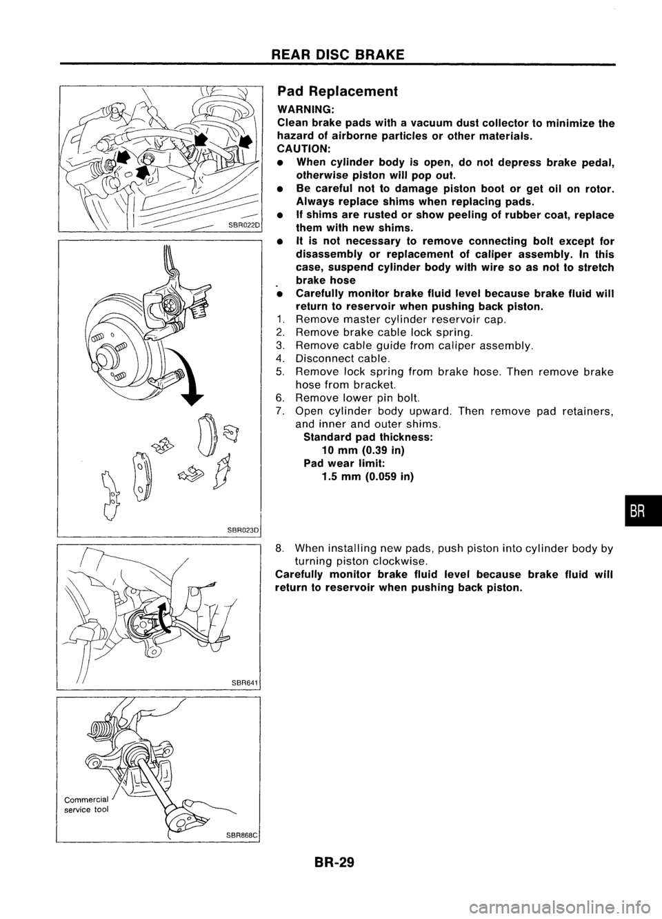
Pad Replacement
WARNING:
Clean brakepadswithavacuum dustcollector tominimize the
hazard ofairborne particles orother materials.
CAUTION:
• When cylinder bodyisopen, donot depress brakepedal,
otherwise pistonwillpop out.
• Becareful nottodamage pistonbootorget oilonrotor.
Always replace shimswhenreplacing pads.
• Ifshims arerusted orshow peeling ofrubber coat,replace
them withnewshims.
• Itis not necessary toremove connecting boltexcept for
disassembly orreplacement ofcaliper assembly. Inthis
case, suspend cylinderbodywithwire soas nol tostreich
brake hose
• Carefully monitorbrakefluidlevel because brakefluidwill
return toreservoir whenpushing backpiston.
1. Remove mastercylinder reservoir cap.
2. Remove brakecablelockspring.
3. Remove cableguide fromcaliper assembly.
4. Disconnect cable.
5. Remove lockspring frombrake hose.Thenremove brake
hose from bracket.
6. Remove lowerpinbolt.
7. Open cylinder bodyupward. Thenremove padretainers,
and inner andouter shims.
Standard padthickness:
10 mm (0.39 in)
Pad wear limit:
1.5 mm (0.059 in)
•
Commercial
service tool
SBR868C
8.
When installing newpads, pushpiston intocylinder bodyby
turning pistonclockwise.
Carefully monitorbrakefluidlevel because brakefluidwill
return toreservoir whenpushing backpiston.
BR-29
Page 392 of 1701

GROUNDDISTRIBUTION
GROUND CONNECTTO CONN.
NO. CELLCORD
E37/E51 AIRBAG DIAGNOSIS SENSORUNIT(Single
E108 RS-SRS
air bag system)
BRAKE FLUIDLEVEL SWITCH E2EL-WARN
CLEARANCE LAMPLH E50EL-TAILIL
CLEARANCE LAMPRH E33EL-TAILIL
COOLING FANMOTOR-1 (1-modetype) E45 EC-COOLIFHA-A/C
COOLING FANMOTOR-1 (2-modetype-GA
E66 EC-COOLIF
HA-A/C
engine forEurope)
COOLING FANMOTOR-1 (2-modetype-ex-
E46 EC-COOLIF
HA-A/C
eept GAengine forEurope)
COOLING FANMOTOR-2 (1-modetype)
E39 EC-COOLIFHA-A/C
-
COOLING FANMOTOR-2 (2-modetype-GA
E67 EC-COOLiF
HA-A/C
engine forEurope)
COOLING FANMOTOR-2 (2-modetype-ex-
E40 EC-COOLIFHA-A/C
eept GAengine forEurope)
COOLING FANRELAY-1 E12
EC-COOLIFHA-A/C
COOLING FANRELAY-2 E17
EC-COOLIFHA-A/C
COOLING FANRELAY-3 E18EC-COOLIF
HA-A/C
DAYTIME LIGHTUNIT E119EL-DTRL
FRONT FOGLAMP LH E52EL-F/FOG
FRONT FOGLAMP RH
E36EL-F/FOG
FRONT TURNSIGNAL LAMPLH E53EC-TURN
FRONT TURNSIGNAL LAMPRH E32EC-TURN
FRONT WIPERANDWASHER SWITCH E113
EL-WIPER
FUEL FILTER SWITCH
E5EL-WARN
HEADLAMP AIMINGMOTOR UNITLH E48
EL-AIM
HEADLAMP AIMINGMOTOR UNITRH E35 EL-AIM
HEADLAMP LH E49EL-H/LAMP
EL-DTRL
HEADLAMP RH E34EL-H/LAMP
EL-DTRL
HEADLAMP WIPERMOTOR LH E44
EL-HLC
HEADLAMP WIPERMOTOR RH E41EL-HLC
IACV-FICD SOLENOID VALVE(LHDmodels
.
E65 EC-A/CCUTHA-A/C
with CD20 engine)
INHIBITOR SWITCH E222EC-PNP/SWAT-A
IT EL-START
NEUTRAL POSITION SWITCH E220EC-PNP/SW
POWER STEERING OILPRESSURE SWITCH
E3 EC-PST/SW
(RHO models withgasoline engine)
REAR FOGLAMP RELAY E20EL-R/FOG
REAR WIPER ANDWASHER SWITCH E112EL-WIP/R
REAR WIPER RELAY E15EL-WIP/R
SIDE TURN SIGNAL LAMP(Driver side) E1 EL-TURN
WASHER FLUIDLEVEL SWITCH E30EL-WARN
EL-20
Page 447 of 1701
Bulbcover
SEL995K HEADLAMP
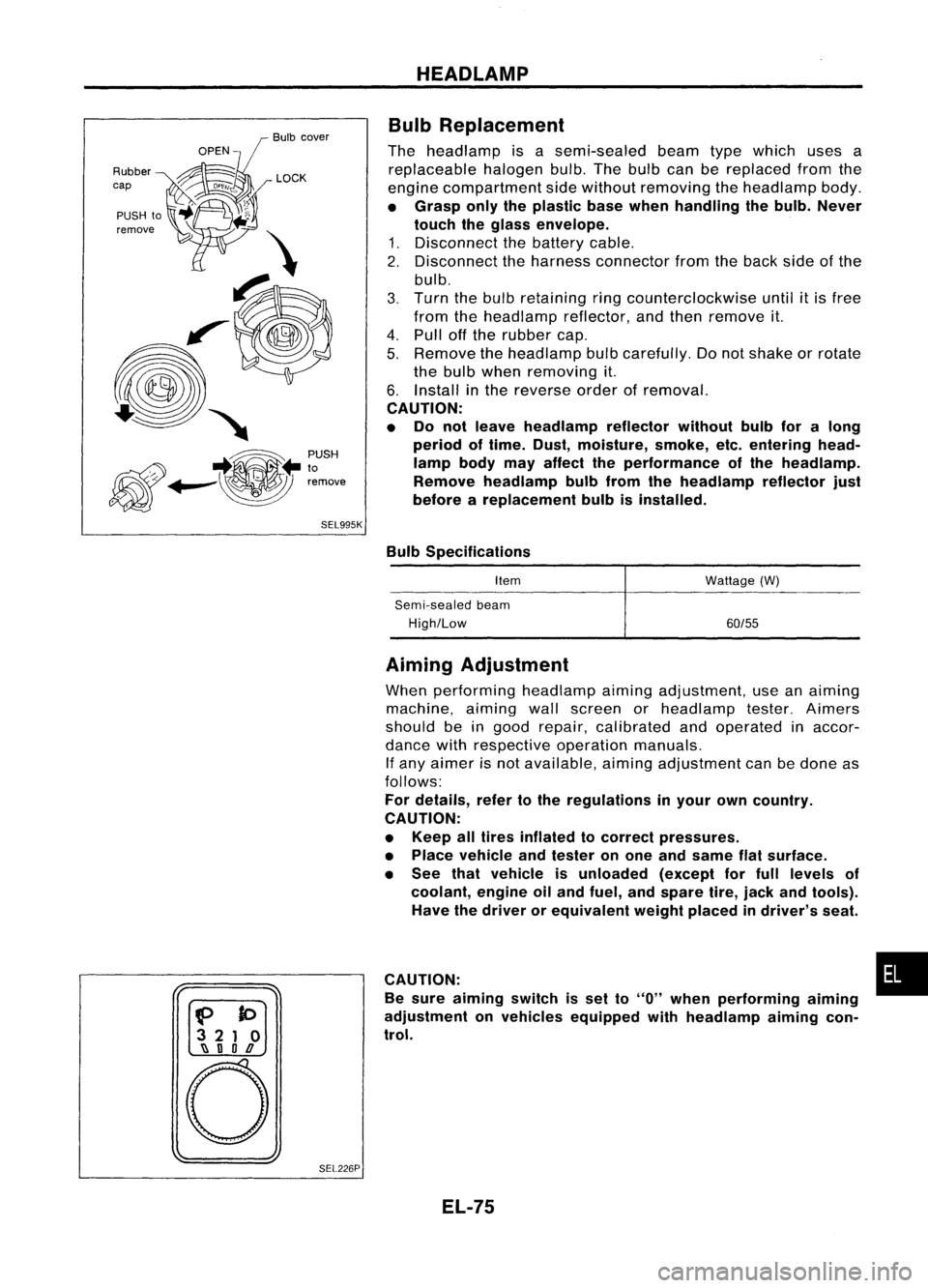
Bulb Replacement
The headlamp isasemi-sealed beamtypewhich usesa
replaceable halogenbulb.Thebulb canbereplaced fromthe
engine compartment sidewithout removing theheadlamp body.
• Grasp onlytheplastic basewhen handling thebulb. Never
touch theglass envelope.
1. Disconnect thebattery cable.
2. Disconnect theharness connector fromtheback sideofthe
bulb.
3. Turn thebulb retaining ringcounterclockwise until
it
is free
from theheadlamp reflector,andthen remove it.
4. Pull offthe rubber cap.
5. Remove theheadlamp bulbcarefully. Donot shake orrotate
the bulb when removing it.
6. Install inthe reverse orderofremoval.
CAUTION:
• Do not leave headlamp reflector withoutbulbforalong
period oftime. Dust,moisture, smoke,etc.entering head-
lamp bodymayaffect theperformance ofthe head lamp.
Remove headlamp bulbfrom thehead lamp reflector just
before areplacement bulbisinstalled.
Bulb Specifications
Item
Semi-sealed beam
High/Low Wattage
(W)
60/55
f>
to
3 21 0
~ nOD
o
SEL226PAiming
Adjustment
When performing headlamp aiming adjustment, useanaiming
machine, aimingwallscreen orheadlamp tester.Aimers
should beingood repair, calibrated andoperated inaccor-
dance withrespective operationmanuals.
If any aimer isnot available, aimingadjustment canbedone as
follows:
For details, refertothe regulations inyour owncountry.
CAUTION:
• Keep alltires inflated tocorrect pressures.
• Place vehicle andtester onone and same flatsurface.
• See thatvehicle isunloaded (exceptforfull levels of
coolant, engineoiland fuel, andspare tire,jack andtools).
Have thedriver orequivalent weightplaced indriver's seat.
CAUTION: •
Be sure aiming switchisset to
"0"
when performing aiming
adjustment onvehicles equipped withheadlamp aiming con-
trol.
EL-75