1995 NISSAN ALMERA N15 tow
[x] Cancel search: towPage 7 of 1701

PREPARATIONANDPRECAUTIONS
Service Notice
Supplemental RestraintSystem(SRS)"AIR
BAG" (DualAirBag System)
The Supplemental RestraintSystem"AirBag" usedalong withaseat belt, helps toreduce therisk or
severity ofinjury tothe driver andfront passenger inafrontal collision. TheSupplemental Restraint
System consists ofair bag modules (locatedinthe center ofthe steering wheelandonthe instrument
panel onthe passenger side),adiagnosis sensorunit,warning lamp,wiring harness andspiral cable.
Information necessarytoservice thesystem safelyisincluded inthe
RSsection
ofthis Service Manual.
WARNING:
• Toavoid rendering theSRS inoperative, whichcouldincrease therisk ofpersonal injuryordeath
in the event ofacollision whichwould resultinair bag inflation, allmaintenance mustbeperformed
by an authorized NISSANdealer.
• Improper maintenance, includingincorrectremovalandinstallation ofthe SRS, canlead topersonal
injury caused byunintentional activationofthe system.
Ii
Donot use electrical testequipment onany circuit related tothe SRS unless instructed tointhis
Service Manual. SRSwiring harnesses arecovered withyellow insulation eitherjustbefore the
harness connectors orfor the complete harness,foreasy identification.
•
Before proceeding withdisassembly, thor-
oughly cleantheoutside ofthe transaxle. Itis
important toprevent theinternal partsfrom
becoming contaminated bydirt orother for-
eign matter.
• Disassembly shouldbedone inaclean work
area.
• Use lint-free clothortowels forwiping parts
clean. Common shopragscanleave fibers
that could interfere withtheoperation ofthe
transaxle.
• Place disassembled partsinorder, onaparts
rack, foreasier andproper assembly.
• Allparts should becarefully cleaned-witha
general purpose, non-flammable solvent
before inspection orreassembly.
• Gaskets, sealsandO-rings shouldbe
replaced anytime thetransaxle isdisassem-
bled.
• Itis very important toperform functional tests
whenever theyareindicated. •
The valve bodycontains precision partsand
requires extremecarewhen partsare
removed andserviced. Placedisassembled
valve bodyparts inorder, onaparts rack,for
easier andproper assembly. Carewillalso
prevent springs andsmall partsfrombecom-
ing scattered orlost.
• Properly installedvales,sleeves, plugs,etc.
will slide along theirbores inthe valve body
under theirownweight.
• Before assembly, applyacoat ofrecom-
mended ATFtoall parts. Apply petroleum
jelly toprotect O-ringandseals, orhold bear-
ings andwashers inplace during assembly.
Do not use grease.
• Extremely careshould betaken toavoid dam-
age toO-rings, sealsandgaskets when
assembling.
• After overhaul, refillthetransaxle withnew
ATF.
•
Supplemental RestraintSystem(SRS)"AIR
BAG" (Single AirBag System)
The Supplemental RestraintSystem"AirBag" andused along withaseat belt,helps toreduce therisk
or severity ofinjury tothe driver inafrontal collision. TheSupplemental RestraintSystemconsists of
an air bag module (located inthe center ofthe steering wheel),adiagnosis sensorunit,warning lamp,
wiring harness andspiral cable. Information necessarytoservice thesystem safelyisincluded inthe
RS section
ofthis Service Manual.
WARNING:
• Toavoid rendering theSRS inoperative, whichcouldincrease therisk ofpersonal injuryordeath
in the event ofacollision whichwould resultinair bag inflation, allmaintenance mustbeperformed
by an authorized NISSANdealer.
• Improper maintenance, includingincorrectremovalandinstallation ofthe SRS, canlead topersonal
injury caused byunintentional activationofthe system.
• Donot use electrical testequipment onany circuit related tothe SRS unless instructed tointhis
Service Manual.
AT-7
Page 24 of 1701
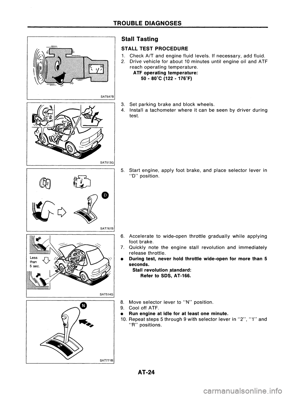
TROUBLEDIAGNOSES
Stall Tasting
STALL TESTPROCEDURE
1. Check
AIT
and engine fluidlevels. Ifnecessary, addfluid.
2. Drive vehicle forabout 10minutes untilengine oiland ATF
reach operating temperature.
ATF operating temperature:
50 -80
0
e (122-176°F)
SAT6478
3.Set parking brakeandblock wheels.
4. Install atachometer whereitcan beseen bydriver during
test.
SAT513G 5.
~ ~ID
•
~c;>
SAT7678
Start
engine, applyfootbrake, andplace selector leverin
"0"
position.
6. Accelerate towide-open throttlegradually whileapplying
foot brake.
7. Quickly notetheengine stallrevolution andimmediately
release throttle.
• During test,never holdthrottle wide-open formore than5
seconds. Stall revolution .standard:
Refer toSDS, AT-166.
SAT514G
8.Move selector leverto"N" position.
9. Cool offATF.
• Run engine atidle foratleast oneminute.
10. Repeat steps5through 9with selector leverin"2", "1"and
"R
n
positions.
SAT7718 AT-24
Page 193 of 1701
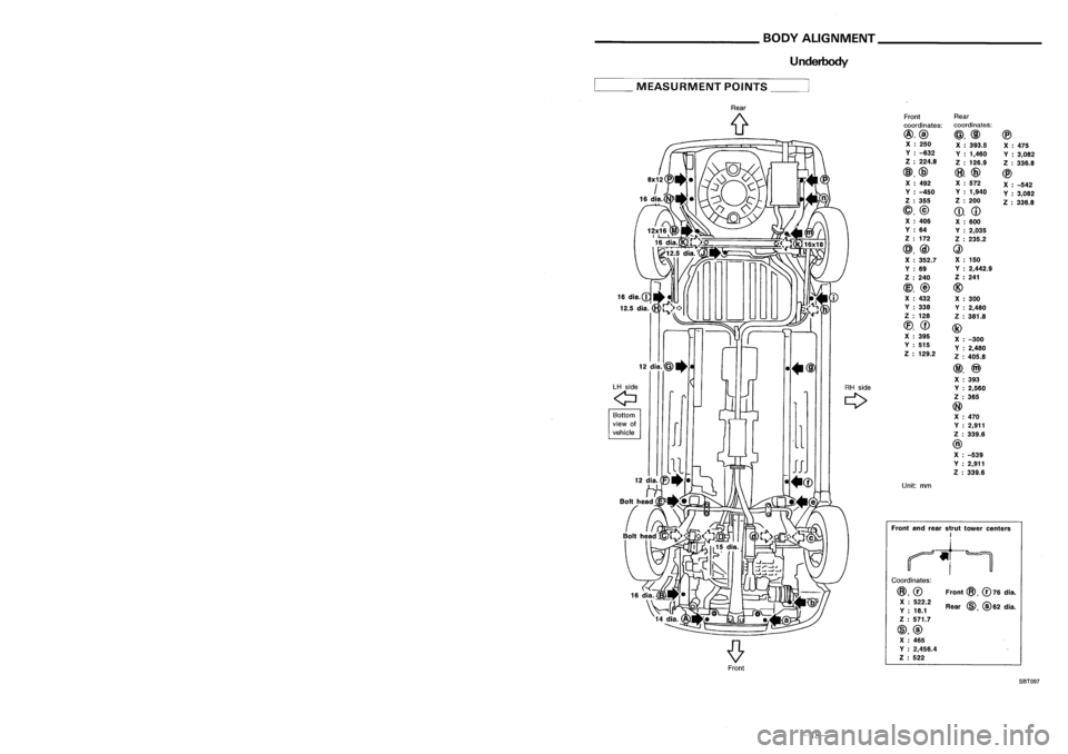
______ HANDLINGPRECAUTIONS FORPLASTICS __
BODYALIGNMENT _
Location OfPlastic Parts
Underbody
Kicking plate(PP)
Front
@,
076
dia.
Rear
@,@
62 dia.
Front
Rear
coordinates: coordinates:
@,@ @,@@
X :250
X:393.5
X:475
V :-632
V:1,460
V:3,082
Z :224.8
Z:126.9
Z:336.8
@,@
(8),
@
@
X :492 X
:572
X:-542
V :-450 V
:1,940
V:3,082
Z :355 Z
:200
Z:336.8
@,@
CD,
CD
X :406
X:600
V :64
V:2,035
Z :172
Z:235.2
@,@
Q)
X :352.7 X
:150
V :69 V
:2,442.9
Z :240 Z
:241
@,
@
@
X :432
X:300
V :338
V:2,480
Z :128
Z:381.8
(f),
CD
@
X :395
X:-300
V :515
V:2,480
Z :129.2
Z:405.8
@,
@)
X :393
Y :2,560
Z :365
@
X :470
Y :2,911
Z :339.6
@
X :-539
Y :2,911
Z :339.6
Unit: mm
Coordinates:
@,0
X :522.2
V :18.1
Z :571.7
@,@ X :465
V :2,456.4
Z :522
Front
andrear strut tower centers
I
~t-~
Rear
(f
••@
LH side
RHside
Q
Q
Bottom
view of
,1
vehicle
__
MEASURMENT POINTS__
Glove box(PPC)
Side
wind molding(PVC)
Cluster lidC(PPC)
Instrument
panel(PPC)
Console box(PPC)
5-door
Hatchback
Cluster lidA(PPC)
~----_/
Front
pillargarnish(PPC)
Side
wind molding(PVC)
Back doorfinisher(ABS)
Roof
spoilar(FRP)
3-doorHatchback
Center pillarlower garnish(PP)
Center pillarupper garnish(PPC)
Rear pillar garnish(PPC)
High
mounted stoplamp
(Lens: PMMA )
Housing: ABS
FrontSBT097
-27-
-18-
Page 202 of 1701
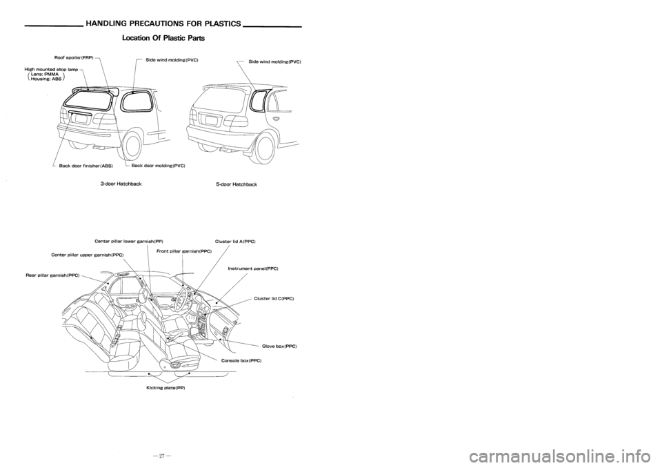
______ HANDLINGPRECAUTIONS FORPLASTICS __
BODYALIGNMENT _
Location OfPlastic Parts
Underbody
Kicking plate(PP)
Front
@,
076
dia.
Rear
@,@
62 dia.
Front
Rear
coordinates: coordinates:
@,@ @,@@
X :250
X:393.5
X:475
V :-632
V:1,460
V:3,082
Z :224.8
Z:126.9
Z:336.8
@,@
(8),
@
@
X :492 X
:572
X:-542
V :-450 V
:1,940
V:3,082
Z :355 Z
:200
Z:336.8
@,@
CD,
CD
X :406
X:600
V :64
V:2,035
Z :172
Z:235.2
@,@
Q)
X :352.7 X
:150
V :69 V
:2,442.9
Z :240 Z
:241
@,
@
@
X :432
X:300
V :338
V:2,480
Z :128
Z:381.8
(f),
CD
@
X :395
X:-300
V :515
V:2,480
Z :129.2
Z:405.8
@,
@)
X :393
Y :2,560
Z :365
@
X :470
Y :2,911
Z :339.6
@
X :-539
Y :2,911
Z :339.6
Unit: mm
Coordinates:
@,0
X :522.2
V :18.1
Z :571.7
@,@ X :465
V :2,456.4
Z :522
Front
andrear strut tower centers
I
~t-~
Rear
(f
••@
LH side
RHside
Q
Q
Bottom
view of
,1
vehicle
__
MEASURMENT POINTS__
Glove box(PPC)
Side
wind molding(PVC)
Cluster lidC(PPC)
Instrument
panel(PPC)
Console box(PPC)
5-door
Hatchback
Cluster lidA(PPC)
~----_/
Front
pillargarnish(PPC)
Side
wind molding(PVC)
Back doorfinisher(ABS)
Roof
spoilar(FRP)
3-doorHatchback
Center pillarlower garnish(PP)
Center pillarupper garnish(PPC)
Rear pillar garnish(PPC)
High
mounted stoplamp
(Lens: PMMA )
Housing: ABS
FrontSBT097
-27-
-18-
Page 253 of 1701
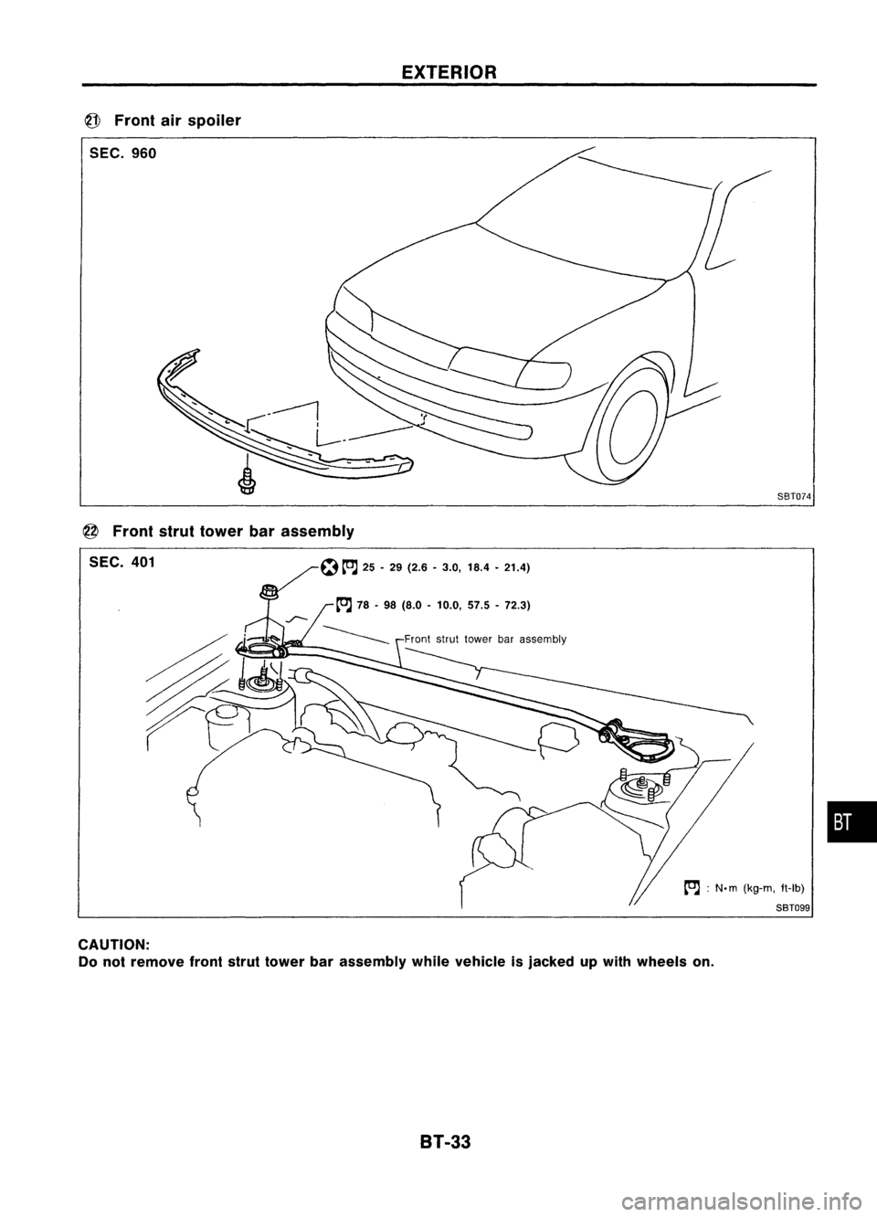
EXTERIOR
@
Front airspoiler
SEC. 960
8BT074
@
Front struttower barassembly
SEC. 401
[OJ:
N.m (kg-m, ft-lb)
8BT099
•
CAUTION:
Do not remove frontstruttower barassembly whilevehicle isjacked upwith wheels on.
8T-33
Page 270 of 1701
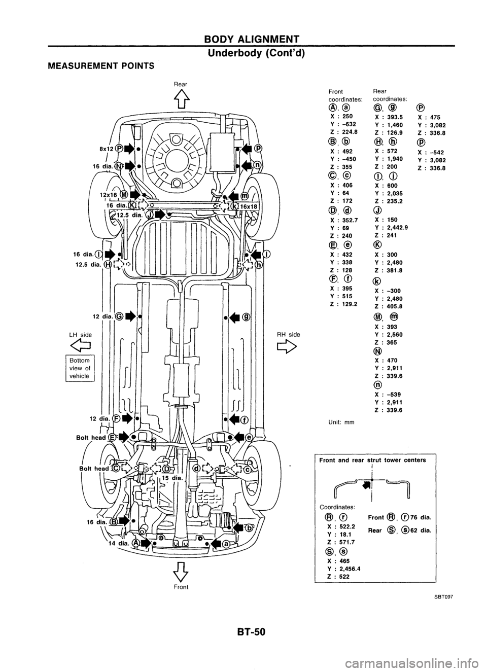
Front
@,
076
dia.
Rear
@,
@62 dia.
Coordinates:
@.0
X :522.2
Y :18.1
Z :571.7
@,@ X :465
Y :2,456.4
Z :522
Front
andrear strut tower centers
I
~-t~
BODY
ALIGNMENT
Underbody (Cont'd)
MEASUREMENT POINTS
Rear
{t
Front
Rear
coordinates: coordinates:
@.@
@.@
@
X :250
X:393.5
X:475
Y :-632
Y:1,460
Y:3,082
Z :224.8
Z:126.9
Z:336.8
@.@
@,
@
@
X :492 X
:572
X:-542
Y :-450 Y
:1,940
Y:3,082
Z :355 Z
:200
Z:336.8
@.@
Q).
CD
X :406
X:600
Y :64
Y:2,035
Z :172
Z:235.2
@.@
Q)
X :352.7 X
:150
Y :69 Y
:2,442.9
Z :240 Z
:241
(g),@ @
X :432
X:300
Y :338
Y:2,480
Z :128 Z:381.8
CEJ,
CD
@
X :395
X:-300
Y :515
Y:2,480
Z :129.2
Z:405.8
12
dia.@.
••@ @.
@)
X :393
LH side RH
side Y:2,560
Q
If
Q
Z
:365
II
@
Bottom X:470
view of Y
:2,911
vehicle Z:339.6
@ X :-539
Y :2,911
Z :339.6
Unit: mm
Front SBT097
BT-50
Page 293 of 1701
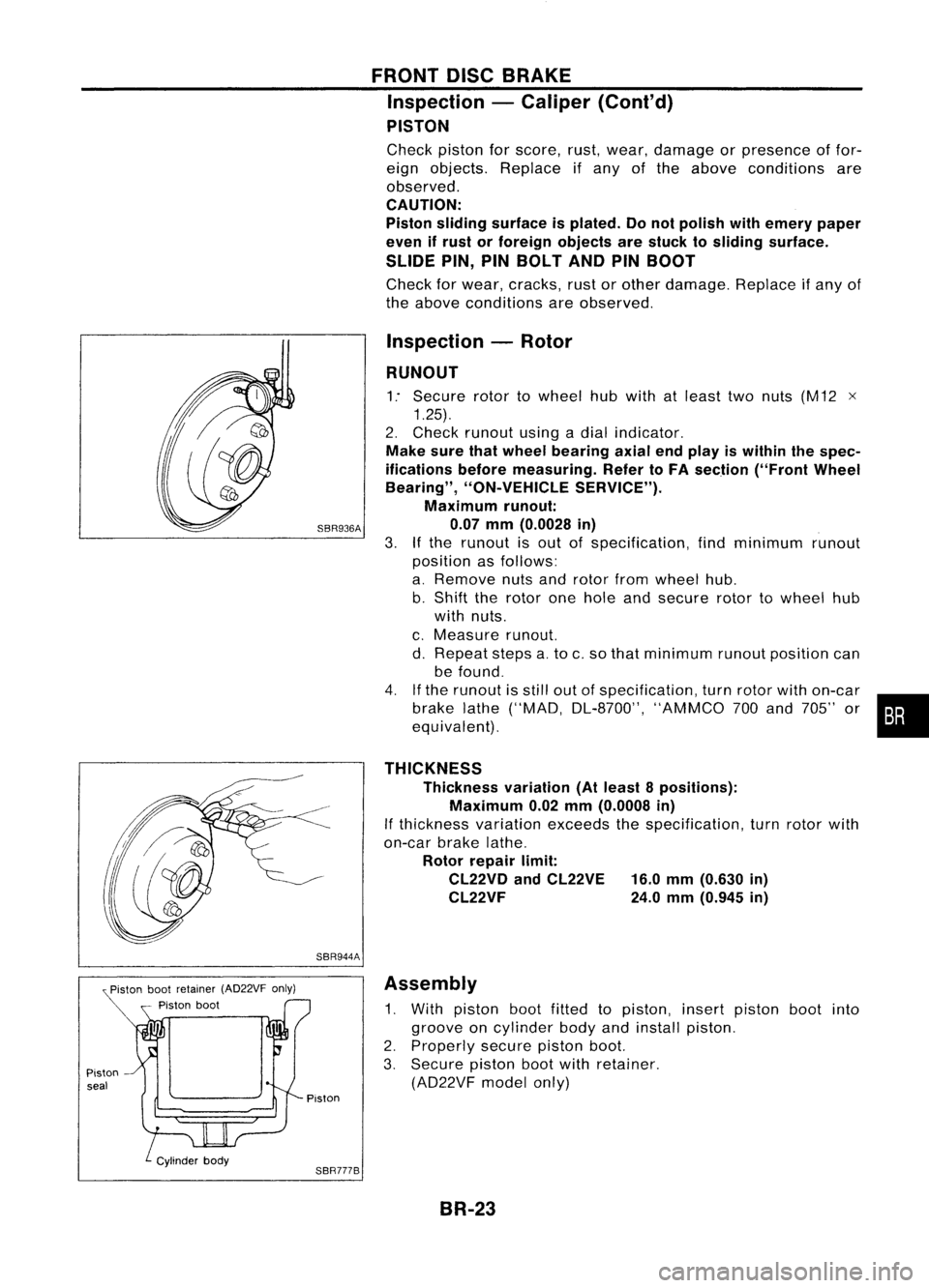
Pistonbootretainer (AD22VF only)
Piston boot
Piston seal
FRONT
DISCBRAKE
Inspection -Caliper (Cont'd)
PISTON
Check pistonforscore, rust,wear, damage orpresence offor-
eign objects. Replace ifany ofthe above conditions are
observed.
CAUTION:
Piston sliding surface isplated. Donot polish withemery paper
even ifrust orforeign objects arestuck tosliding surface.
SLIDE PIN,PINBOLT ANDPINBOOT
Check forwear, cracks, rustorother damage. Replaceifany of
the above conditions areobserved.
Inspection -Rotor
RUNOUT
1: Secure rotortowheel hubwith atleast twonuts (M12 x
1.25).
2. Check runout usingadial indicator.
Make surethatwheel bearing axialendplay iswithin thespec-
ifications beforemeasuring. RefertoFA section ("FrontWheel
Bearing", "ON-VEHICLE SERVICE").
Maximum runout:
SBR936A 0.07mm(0.0028 in)
3.
If
the runout isout ofspecification, findminimum runout
position asfollows:
a. Remove nutsandrotor fromwheel hub.
b. Shift therotor onehole andsecure rotortowheel hub
with nuts.
c. Measure runout.
d. Repeat stepsa.to c.so that minimum runoutposition can
be found.
4. Ifthe runout isstill outofspecification, turnrotor withon-car
brake lathe("MAD, DL-8700", "AMMCO700and 705" or•••
equivalent).
THICKNESS Thickness variation(Atleast 8positions):
Maximum 0.02mm(0.0008 in)
If thickness variationexceedsthespecification, turnrotor with
on-car brakelathe.
Rotor repair limit:
CL22VD andCL22VE 16.0mm(0.630 in)
CL22VF 24.0mm(0.945 in)
SBR944A Assembly
1. With piston bootfitted topiston, insertpiston bootinto
groove oncylinder bodyandinstall piston.
2. Properly securepistonboot.
3. Secure pistonbootwithretainer.
(AD22VF modelonly)
Piston
SBR777B BR-23
Page 303 of 1701
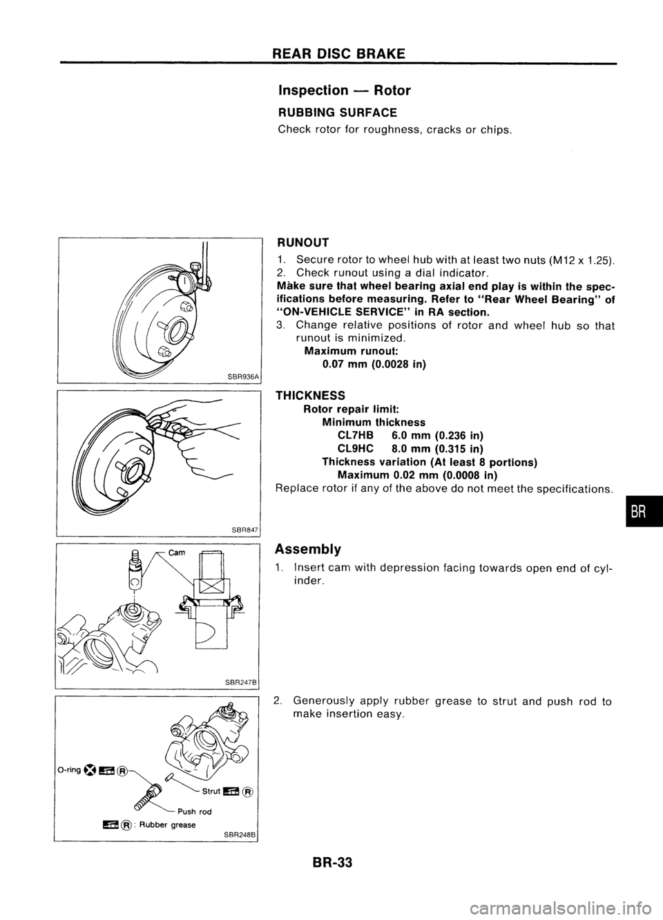
SBR847
SBR247B REAR
DISCBRAKE
Inspection -Rotor
RUBBING SURFACE
Check rotorforroughness, cracksorchips.
RUNOUT
1. Secure rotortowheel hubwith atleast twonuts (M12 x1.25).
2. Check runout usingadial indicator.
Make surethatwheel bearing axialendplay iswithin thespec-
ifications beforemeasuring. Referto"Rear Wheel Bearing" of
"ON-VEHICLE SERVICE"inRA section.
3. Change relativepositions ofrotor andwheel hubsothat
runout isminimized.
Maximum runout:
0.07 mm(0.0028 in)
THICKNESS Rotor repair limit:
Minimum thickness
CL7HB 6.0mm (0.236 in)
CL9HC 8.0mm (0.315 in)
Thickness variation(Atleast 8portions)
Maximum 0.02mm(0.0008 in)
Replace rotorifany ofthe above donot meet thespecifications .
Assembly
1. Insert camwithdepression facingtowards openendofcyl-
inder.
2. Generously applyrubber grease tostrut andpush rodto
make insertion easy.
BR-33
•