1995 NISSAN ALMERA N15 automatic transmission fluid
[x] Cancel search: automatic transmission fluidPage 1362 of 1701
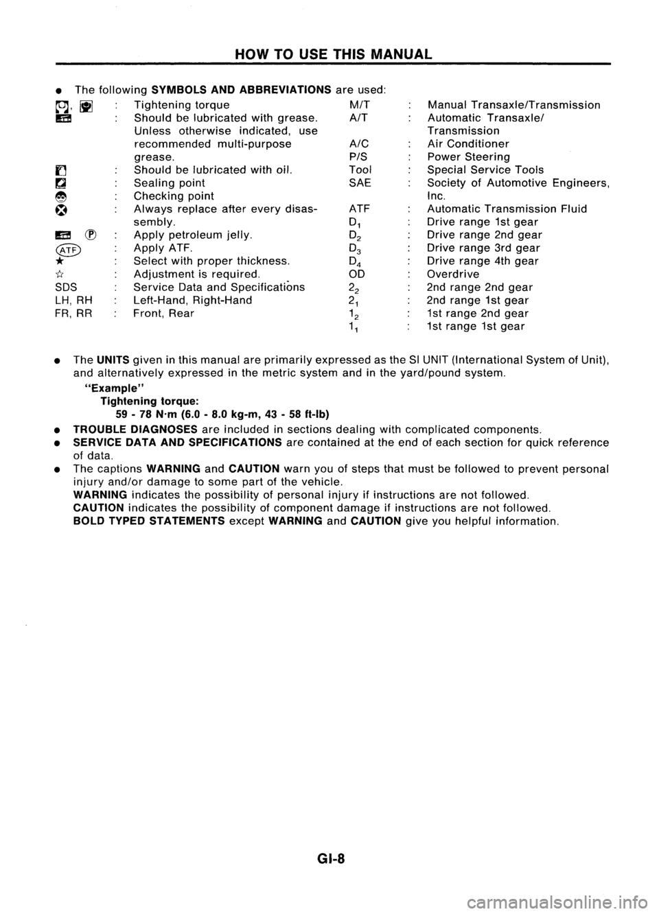
HOWTOUSE THIS MANUAL
ManualTransaxle/Transmission
Automatic Transaxle/
Transmission
Air Conditioner
Power Steering
Special Service Tools
Society ofAutomotive Engineers,
Inc.
Automatic Transmission Fluid
Drive range 1stgear
Drive range 2ndgear
Drive range 3rdgear
Drive range 4thgear
Overdrive
2nd range 2ndgear
2nd range 1stgear
1st range 2ndgear
1st range 1stgear
A/C
PIS
Tool SAE
ATF
0
1
O
2
0
3
0
4
00
2
2
2
1
1
2
1
1
•
The following
SYMBOLS ANDABBREVIATIONS
areused:
to;J,
l\tI
Tightening torque M/T
IE!
Shouldbelubricated withgrease. A/T
Unless otherwise indicated,use
recommended multi-purpose
grease.
Should belubricated withoil.
Sealing point
Checking point
Always replaceafterevery disas-
sembly.
Apply petroleum jelly.
Apply ATF.
Select withproper thickness.
Adjustment isrequired.
Service DataandSpecifications
Left-Hand, Right-Hand
Front, Rear
IE!
~
@
*
1I
SDS LH, RH
FR, RR
• The
UNITS
giveninthis manual areprimarily expressed asthe SlUNIT (International SystemofUnit),
and alternatively expressedinthe metric system andinthe yard/pound system.
"Example" Tightening torque:
59 -78 N'm (6.0-8.0 kg-m, 43-58 ft-Ib)
• TROUBLE DIAGNOSES
areincluded insections dealingwithcomplicated components.
• SERVICE DATAANDSPECIFICATIONS
arecontained atthe end ofeach section forquick reference
of data.
• The captions
WARNING
and
CAUTION
warnyouofsteps thatmust befollowed toprevent personal
injury and/or damage tosome partofthe vehicle.
WARNING
indicatesthepossibility ofpersonal injuryifinstructions arenotfollowed.
CAUTION
indicatesthepossibility ofcomponent damageifinstructions arenotfollowed.
BOLD TYPED STATEMENTS
except
WARNING
and
CAUTION
giveyouhelpful information.
GI-8
Page 1491 of 1701
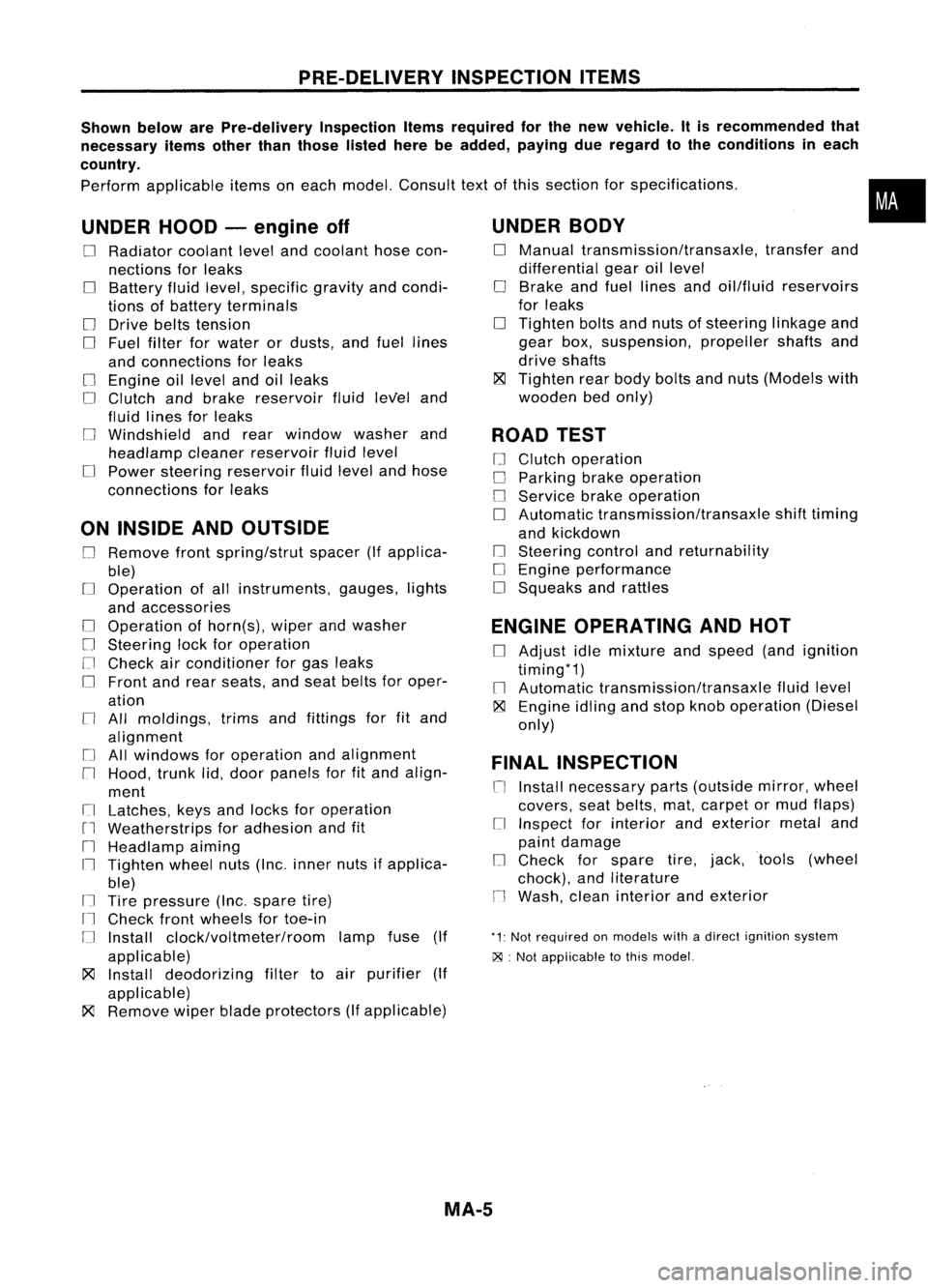
PRE-DELIVERYINSPECTIONITEMS
Shown belowarePre-delivery InspectionItemsrequired forthe new vehicle. Itis recommended that
necessary itemsotherthanthose listedherebeadded, payingdueregard tothe conditions ineach
country.
Perform applicable itemsoneach model. Consult textofthis section forspecifications .
UNDER HOOD-engine off
o
Radiator coolantlevelandcoolant hosecon-
nections forleaks
o
Battery fluidlevel, specific gravityandcondi-
tions ofbattery terminals
o
Drive beltstension
D
Fuel filter forwater ordusts, andfuel lines
and connections forleaks
[] Engine oillevel andoilleaks
D
Clutch andbrake reservoir fluidlevel and
fluid lines forleaks
o
Windshield andrear window washerand
headlamp cleanerreservoir fluidlevel
D
Power steering reservoir fluidlevel andhose
connections forleaks
ON INSIDE ANDOUTSIDE
D
Remove frontspring/strut spacer(Ifapplica-
ble)
D
Operation ofall instruments, gauges,lights
and accessories
o
Operation ofhorn(s), wiperandwasher
[] Steering lockforoperation
[] Check airconditioner forgas leaks
o
Front andrear seats, andseat belts foroper-
ation
n
All moldings, trimsandfittings forfitand
alignment
[J
Allwindows foroperation andalignment
n
Hood, trunklid,door panels forfitand align-
ment
[1
Latches, keysandlocks foroperation
rl
Weatherstrips foradhesion andfit
[l
Headlamp aiming
I~ Tighten wheelnuts(Inc. inner nutsifapplica-
ble)
IJ Tire pressure (Inc.spare tire)
Il
Check frontwheels fortoe-in
IJ Install clock/voltmeter/room lampfuse(If
applicable)
~ Install deodorizing filtertoair purifier (If
applicable)
~ Remove wiperbladeprotectors (Ifapplicable)
UNDER
BODY
o
Manual transmission/transaxle, transferand
differential gearoillevel
D
Brake andfuel lines andoil/fluid reservoirs
for leaks
D
Tighten boltsandnuts ofsteering linkageand
gear box,suspension, propellershaftsand
drive shafts
~ Tighten rearbody boltsandnuts (Models with
wooden bedonly)
ROAD TEST
D
Clutch operation
D
Parking brakeoperation
[J
Service brakeoperation
D
Automatic transmission/transaxle shifttiming
and kickdown
[] Steering controlandreturnability
o
Engine performance
D
Squeaks andrattles
ENGINE OPERATING ANDHOT
D
Adjust idlemixture andspeed (andignition
timing*1)
n
Automatic transmission/transaxle fluidlevel
~ Engine idlingandstop knob operation (Diesel
only)
FINAL INSPECTION
n
Install necessary parts(outside mirror,wheel
covers, seatbelts, mat,carpet ormud flaps)
[1
Inspect forinterior andexterior metaland
paint damage
[] Check forspare tire,jack, tools (wheel
chock), andliterature
n
Wash, cleaninterior andexterior
"1: Not required onmodels withadirect ignition system
~ :Not appiicable tothis model.
•
MA-5
Page 1536 of 1701
0
0
•
0
0
~ /0
H
H
0
0
(2)
4wheels
5 wheels
SMA785C
Radial
tires
CHASSIS
ANDBODY MAINTENANCE
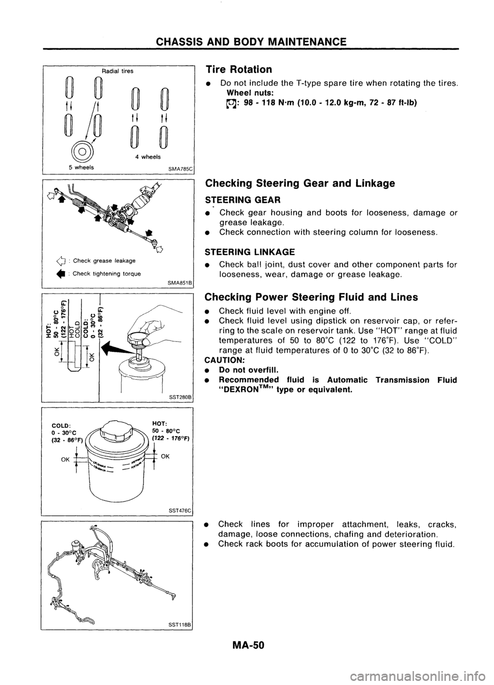
Tire Rotation
Do not include theT-type sparetirewhen rotating thetires .
Wheel nuts:
~: 98-118 N'm (10.0 -12.0 kg-m, 72-87 ft-Ib)
Q :
Check grease leakage
• :Check tightening torque
Checking
SteeringGearandLinkage
STEERING GEAR
• Check gearhousing andboots forlooseness, damageor
grease leakage.
• Check connection withsteering columnforlooseness.
STEERING LINKAGE
• Check balljoint, dustcover andother component partsfor
looseness, wear,damage orgrease leakage.
SMA851B
Checking PowerSteering FluidandLines
• Check fluidlevel withengine off.
• Check fluidlevel using dipstick onreservoir cap,orrefer-
ring tothe scale onreservoir tank.Use"HOT" rangeatfluid
temperatures of50 to80°C (122to176°F). Use"COLD"
range atfluid temperatures of
a
to 30°C (32to86°F).
CAUTION:
• Donot overfill.
• Recommended fluidisAutomatic Transmission Fluid
''DEXRON™,, typeorequivalent.
SST280B
SST476C
•Check linesforimproper attachment, leaks,cracks,
damage, looseconnections, chafinganddeterioration.
• Check rackboots foraccumulation ofpower steering fluid.
MA-50
Page 1668 of 1701
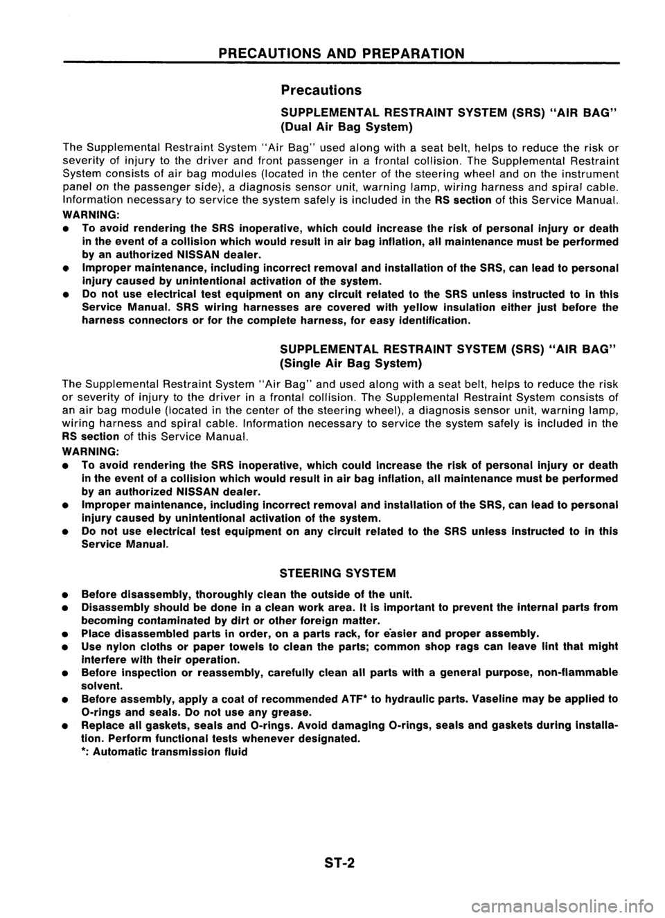
PRECAUTIONSANDPREPARATION
Precautions
SUPPLEMENTAL RESTRAINTSYSTEM(SRS)"AIRBAG"
(Dual AirBag System)
The Supplemental RestraintSystem"AirBag" usedalong withaseat belt,helps toreduce therisk or
severity ofinjury tothe driver andfront passenger inafrontal collision. TheSupplemental Restraint
System consists ofair bag modules (locatedinthe center ofthe steering wheelandonthe instrument
panel onthe passenger side),adiagnosis sensorunit,warning lamp,wiring harness andspiral cable.
Information necessarytoservice thesystem safelyisincluded inthe
RSsection
ofthis Service Manual.
WARNING: • Toavoid rendering theSRS inoperative, whichcouldincrease therisk ofpersonal injuryordeath
in the event ofacollision whichwould resultinair bag inflation, allmaintenance mustbeperformed
by an authorized NISSANdealer.
• Improper maintenance, includingincorrectremovalandinstallation ofthe SRS, canlead topersonal
injury caused byunintentional activationofthe system.
• Donot use electrical testequipment onany circuit related tothe SRS unless instructed tointhis
Service Manual. SRSwiring harnesses arecovered withyellow insulation eitherjustbefore the
harness connectors orfor the complete harness,foreasy identification.
SUPPLEMENTAL RESTRAINTSYSTEM(SRS)"AIRBAG"
(Single AirBag System)
The Supplemental RestraintSystem"AirBag" andused along withaseat belt,helps toreduce therisk
or severity ofinjury tothe driver inafrontal collision. TheSupplemental RestraintSystemconsists of
an air bag module (located inthe center ofthe steering wheel),adiagnosis sensorunit,warning lamp,
wiring harness andspiral cable. Information necessarytoservice thesystem safelyisincluded inthe
RS section
ofthis Service Manual.
WARNING: • Toavoid rendering theSRS inoperative, whichcouldincrease therisk ofpersonal injuryordeath
in the event ofacollision whichwould resultinair bag inflation, allmaintenance mustbeperformed
by an authorized NISSANdealer.
• Improper maintenance, includingincorrectremovalandinstallation ofthe SRS, canlead topersonal
injury caused byunintentional activationofthe system.
• Donot use electrical testequipment onany circuit related tothe SRS unless instructed tointhis
Service Manual.
STEERINGSYSTEM
• Before disassembly, thoroughlycleantheoutside ofthe unit.
• Disassembly shouldbedone inaclean workarea. Itis important toprevent theinternal partsfrom
becoming contaminated bydirt orother foreign matter.
• Place disassembled partsinorder, onaparts rack,fore"asier andproper assembly.
• Use nylon cloths orpaper towels toclean theparts; common shopragscanleave lintthat might
interfere withtheir operation.
• Before inspection orreassembly, carefullycleanallparts withageneral purpose, non-flammable
solvent.
• Before assembly, applyacoat ofrecommended ATF*tohydraulic parts.Vaseline maybeapplied to
O-rings andseals. Donot use any grease.
• Replace allgaskets, sealsandO-rings. Avoiddamaging O-rings,sealsandgaskets duringinstalla-
tion. Perform functional testswhenever designated.
*:
Automatic transmission fluid
ST-2
Page 1672 of 1701
ON-VEHICLESERVICE
Checking andAdjusting DriveBelts(Forpower
steering)
Refer to"Checking DriveBelts" for"ENGINE MAINTENANCE"
in MA section.
SST476C
S
r
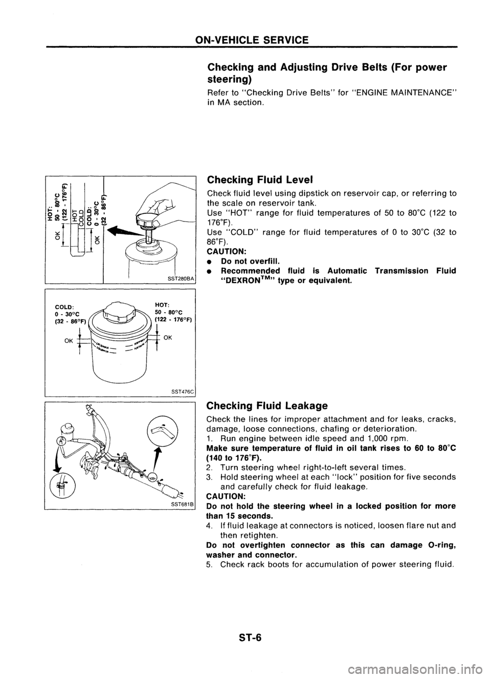
SST681B Checking
Fluidlevel
Check fluidlevel using dipstick onreservoir cap,orreferring to
the scale onreservoir tank.
Use "HOT" rangeforfluid temperatures of50 to80°C (122to
176°F).
Use "COLD" rangeforfluid temperatures of0to 30°C (32to
86°F).
CAUTION:
• Donot overfill.
• Recommended fluidisAutomatic Transmission Fluid
''DEXRON™,, typeorequivalent.
Checking Fluidleakage
Check thelines forimproper attachment andforleaks, cracks,
damage, looseconnections, chafingordeterioration.
1. Run engine between idlespeed and1,000 rpm.
Make suretemperature offluid inoil tank rises to60 to80°C
(140 to176°F).
2. Turn steering wheelright-to-Ieft severaltimes.
3. Hold steering wheelateach "lock" position forfive seconds
and carefully checkforfluid leakage.
CAUTION:
Do not hold thesteering wheelinalocked position formore
than 15seconds.
4. Iffluid leakage atconnectors isnoticed, loosenflarenutand
then retighten.
Do not overtighten connectorasthis candamage O-ring,
washer andconnector.
5. Check rackboots foraccumulation ofpower steering fluid.
ST-6
Page 1687 of 1701
![NISSAN ALMERA N15 1995 Service Manual POWERSTEERING GEARANDLINKAGE (ModelPR24AC)
•
~ :N.m (kg-m. ft-lb)
f] :
Lubrication points
(With automatic
transmission fluid
"DEXRON'u" type
or equivalent)
I
@~~~~
~~(SRandCD
~ ~~ e NISSAN ALMERA N15 1995 Service Manual POWERSTEERING GEARANDLINKAGE (ModelPR24AC)
•
~ :N.m (kg-m. ft-lb)
f] :
Lubrication points
(With automatic
transmission fluid
"DEXRON'u" type
or equivalent)
I
@~~~~
~~(SRandCD
~ ~~ e](/manual-img/5/57349/w960_57349-1686.png)
POWERSTEERING GEARANDLINKAGE (ModelPR24AC)
•
~ :N.m (kg-m. ft-lb)
f] :
Lubrication points
(With automatic
transmission fluid
"DEXRON'u" type
or equivalent)
I
@~~~~
~~(SRandCD
~ ~~ enginemodels)
8
~78. 98
(8.0 •10.0,
58•72)
GA engine model
~ 37•46 (3.8 •4.7, 27.34)
CD and SRengine models
M
78.98
(8.0 •
10.0, 58•72)
(SR
,,'CD,",,",
m_"'7
~\Il~
m~
@,
~16.21
~~'" ~•'.1, ". 1S(
r
, @
l"J
::'0' ,':0,
1
I
~ /7'
~y
@ "-~~(]
tGi ~
~m
@
t:;;J
~20.
26
(2.0 •2.7, 14•20)
SEC.
492
@)(]~\-
.~
~'
r
L
~to:J59' 74
20~
(6.0 •
7.5, 43.54)
_~ @Donotdisas~smble.
0
to:J 29•39
{3.0 .4.0,22. "~~
SST506CA
Pinion oilseal
Lock nut
Adjusting screw
Spring
Spring disc
G)
Rear cover cap
@
Rear housing assembly
@
Pinion sealring
@
Pinion assembly
CID
O-ring
@
Shim
(J)
@
@
@)
@ @
Washer
@
Spring seat
@
Retainer
@
Gear housing
@
Center bushing
@
Rack oilseal
@
Rack assembly
@
Rack sealring
@)
O-ring
@
Rack oilseal
@
Endcover assembly
@
Boot clamp
@
Dust boot
@
Boot band
@l
Steering gearspacer
@
Lock plate
@
Tie-rod innersocket
@
Tie-rod outersocket
@
Cotter pin
@
Gear housing tube
ST-21
Page 1688 of 1701
POWERSTEERING GEARANDLINKAGE (ModelPR24AC)
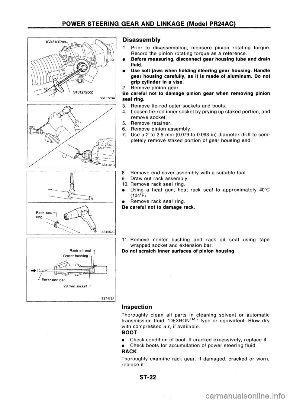
Disassembly
1. Prior todisassembling, measurepinionrotating torque.
Record thepinion rotating torqueasareference.
• Before measuring, disconnectgearhousing tubeanddrain
fluid.
• Use softjaws when holding steering gearhousing. Handle
gear housing carefully, asitis made ofaluminum. Donot
grip cylinder inavise.
2. Remove piniongear.
Be careful nottodamage piniongearwhen removing pinion
seal ring.
3. Remove tie-rodoutersockets andboots.
4. Loosen tie-rodinnersocket byprying upstaked portion, and
remove socket.
5. Remove retainer.
6. Remove pinionassembly.
7. Use a2to 2.5 mm (0.079 to0.098 in)diameter drilltocom-
pletely remove stakedportion ofgear housing end.
8. Remove endcover assembly withasuitable tool.
9. Draw outrack assembly.
10. Remove rackseal ring.
• Using aheat gun,heat racksealtoapproximately 40°C
(104°F).
• Remove racksealring.
Be careful nottodamage rack.
11. Remove centerbushing andrack oilseal using tape
wrapped socketandextension bar.
Do not scratch innersurfaces ofpinion housing .
.. !tension bar
29 mm socket
SST472AInspection
Thoroughly cleanallparts incleaning solventorautomatic
transmission fluid''DEXRON™,, typeorequivalent. Blowdry
with compressed air,ifavailable.
BOOT
• Check condition ofboot. Ifcracked excessively, replaceit.
• Check bootsforaccumulation ofpower steering fluid.
RACK
Thoroughly examinerackgear. Ifdamaged, crackedorworn,
replace it.
ST-22
Page 1695 of 1701
POWERSTEERING OILPUMP
•
SST569C
SEC.
490
SR engine model~
To engine
~26. 36~ ,/"~
;~7 ..
':ij m '-/
~/i<> ·"-
~':J ~
@
'CJ!I",
1~ ........To engine
~16_22 (1.6•2.2, 12•16)
~ 45-60
(4.6 -6.1, 33-44)
SEC.
493 GAengine model
~16-21 [ij6.3.8.3
(1.6. 2.1,12
'Z5)
(0.64.0.85,
To engine
55.6:/73.8)
@ @" ./'----~
, "I
/e;..
~ 31•42 ',.., 0
.'$>J
K@
J:
<~~~iX':I~
Toengine
\1f!.7~
Pm
16-21
v. ~-..
, "~ ~1.6'2.1,12•15)
~ 16. 21 _~
(1.6 -2.1, 12. 15) ~
54.68
{5.5 -6.9,
40 -50~
~ 13.3. 18.0
. (1.36•1.84,
.G
@)
0
CD engine model
9.8_13.3) ../
/3
5
0
~ 16-21 (1.6 -2.1, 12-15)
l.~
@@ ,
~engine @
@Of1--! ~
2
" ," I~
.' "@
It. 17
0
f1 ~ ~~ 3lEi! 10~
69-78
37 •50 /,
'-l
18
f1
..>
lei
51•58)
(3.8. 5.1,27.37)
0,
:r:
19
0()
W
~Q
@
GA16
with
ASS
c:>
1578
0.
Except
GA16
with
ASS
,d
e7
b
Except
GA16 ITh~ .
6? ~
<:>
withASS
-J.1;~
~ 31-42 (3.2 -4.3, 23-31) ()
C'
0
I
() @~
49.69 (5.0-7.0,36 -51)
CD engine
:7 ~~
21
Pay attention
d I
f:j
0:\
toits direction.
mo e -'" ()
-~
~ 27-35 \)~
00
22
(2.8 -3.6, ~,~
23
20 _26)
ri /
~ 13.3 -18.0 ~~
2~ /
~1'36 •1.84,
9.8 •13.3)
13R
engi~e
model
J ~
CD engine model
I
') 26 ~
13.3. 18.0
Y.l~6 14
jGA16
with
ASS
/// (1.36-
1.84f \
-\:f
14~
13.3 -18.0
9.8 •13.3)
I() \\"-/
(1.36•1.84,
/ 09.8-13.3)
~ 27.35:~)-e /
I
\~'l ~
27-35
~l)~ / Except
GA16
with
ASS
(2.8 -3.6~ III~..::::-- (2.8-3.6, ~27•35
20 •26) \)20-26) ~ (2.8_3.6, 20_26)
~ :N'm (kg-m, It-Ib)
f]:
Lubrication points(Withautomatic transmission
[ij :
N'm (kg-m, in-Ib) fluid''DEXRON™,, typeorequivalent)
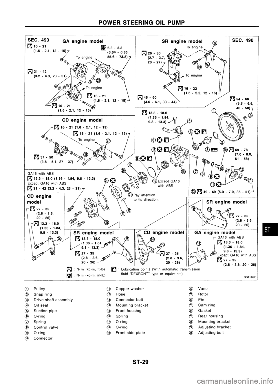
CD
Pulley
@
Copper washer @
Vane
@
Snap ring
@
Hose
@
Rotor
@ Drive shaftassembly
@
Connector boll
@
Pin
@ Oilseal
@
Mounting bracket
@
Carn ring
@
Suction pipe
@
Front housing
@
Gasket
@
O-ring
@l
Spring
@
Rear housing
0
Spring
@
O-ring
@
Mounting bracket
@
Control valve @O-ring
@
Adjusting bracket
@ O-ring
@)
Front sideplate @
Adjusting boll
@)
Connector
ST-29