Page 1319 of 1701

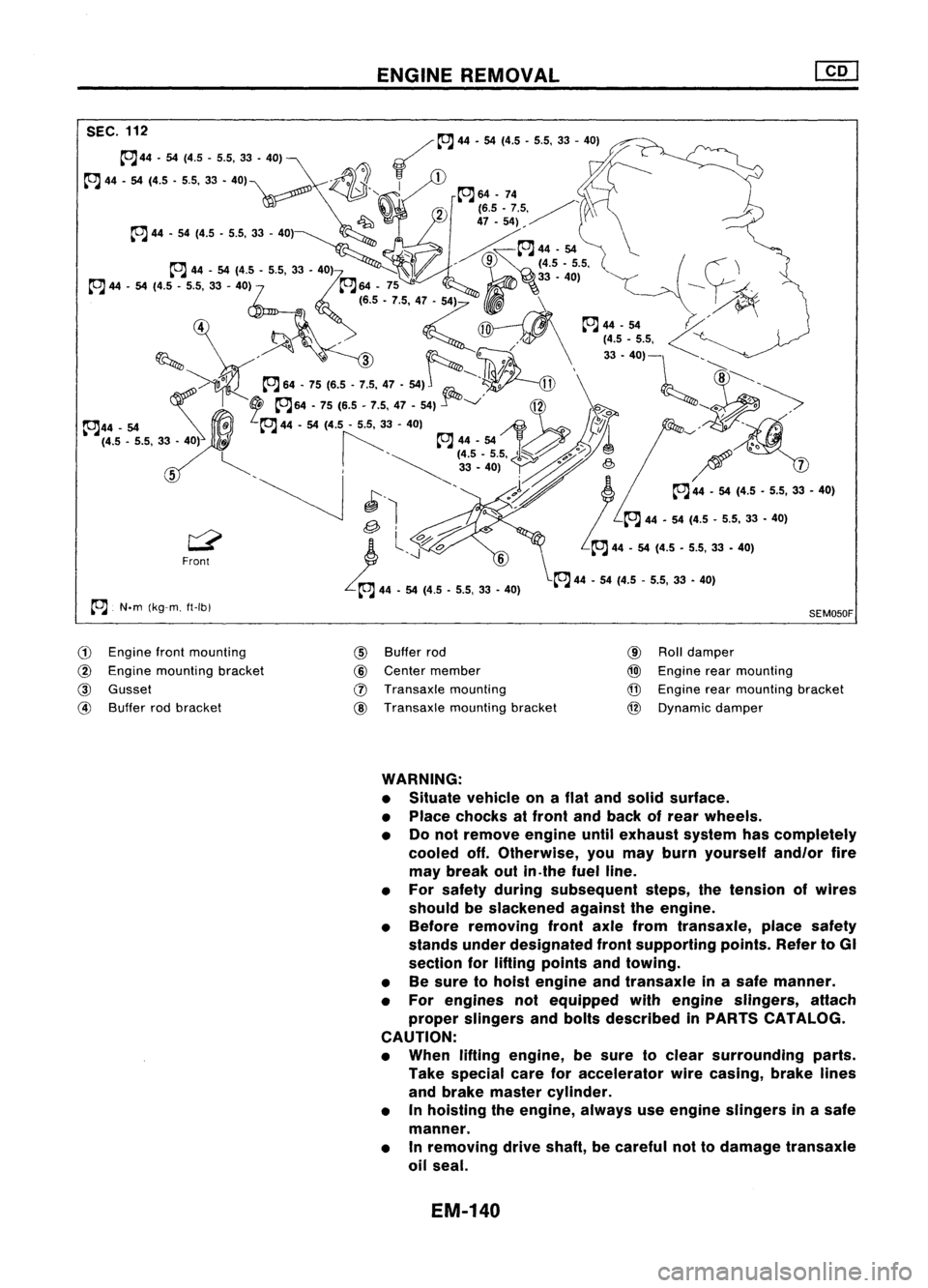
SEC.112 ENGINE
REMOVAL
~~ 44.54(4.5.5.5,33 -40)
~44 .54 (4.5 .5.5, 33.40) ~~
~ 44•54 (4.5 .5.5, 33•40)"\ ~
-~1J.
~1
~~' ~64.74,
_' 2
(6.5.7.5, / \
~ 47.54),/'
rJ44. 54(4.5.5.5,33 -40) ~\
'" ~~~44.54 \....
.- ,9
(4.5.5.5,
ttJJ 44-54 (4.5 •5.5, 33-40)
7
ttJJ64.75 ------~
@--."
('.5•7.5, 4~' \
y~
~~.~~ ~~f;fi\
~~~'~i':-l~"
k(j' --.
II!~o' ~
/'Oolk..,
ttJJ64.75 (6.5•7.5, 47•54) ~
~'o
@\
8,.'~
~- I
2
rJ64. 75(6.5 .7.5,47.54)..1"""-../
~2ft -."~
°
>
~44. 54
~@
ttJJ44.54(4.5 -5.5, 33. 40)
j~~~1 ~-/.~/
(4.5 -5.5, 33•40)
ti ~~
44•54
~'@
A
5~'
!-'~
~35'-4~.)5'~ ~/
,0
7
~ I~. '
.Vi
rJ44.54(4.5.5.5,33.40)
~ ~l
ttJJ44•54 (4.5 •5.5, 33•40)
~ 'l
o.o~
I...",;S'"
1.
..J'-;:7o
6
ttJJ44.54 (4.5 •5.5, 33•40)
~l \
'LrJ 44•54 (4.5 -5.5, 33•40)
ttJJ 44.54 (4.5 .5_5, 33.40)
rJ
N.m(kg-m. ft-Ibl
G)
Engine frontmounting
@
Engine mounting bracket
@
Gusset
@
Buffer rodbracket
@
Buffer rod
@
Center member
(J)
Transaxle mounting
@
Transaxle mountingbracket
SEM050F
@
Rolldamper
@)
Engine rearmounting
@
Engine rearmounting bracket
@
Dynamic damper
WARNING:
• Situate vehicle onaflat and solid surface.
• Place chocks atfront andback ofrear wheels.
• Donot remove engineuntilexhaust systemhascompletely
cooled off.Otherwise, youmay burn yourself and/orfire
may break outin.the fuel line.
• For safety during subsequent steps,thetension ofwires
should beslackened againsttheengine.
• Before removing frontaxlefrom transaxle, placesafety
stands underdesignated frontsupporting points.RefertoGI
section forlifting points andtowing.
• Besure tohoist engine andtransaxle inasafe manner.
• For engines notequipped withengine slingers, attach
proper slingers andbolts described inPARTS CATALOG.
CAUTION:
• When liftingengine, besure toclear surrounding parts.
Take special careforaccelerator wirecasing, brakelines
and brake master cylinder.
• Inhoisting theengine, alwaysuseengine slingers inasafe
manner.
• Inremoving driveshaft, becareful nottodamage transaxle
oil seal.
EM-140
Page 1355 of 1701

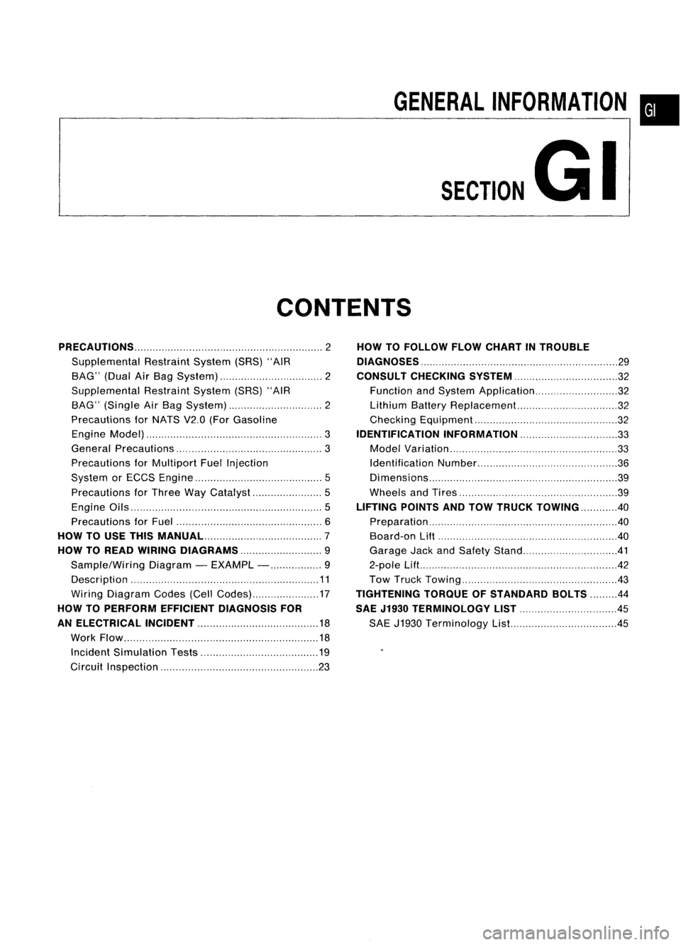
GENERALINFORMATION •
SECTION
G
I
CONTENTS
PRECAUTIONS 2
Supplemental RestraintSystem(SRS)"AIR
BAG" (DualAirBag System) 2
Supplemental RestraintSystem(SRS)"AIR
BAG" (Single AirBag System) 2
Precautions forNATS V2.0(ForGasoline
Engine Model) 3
General Precautions 3
Precautions forMultiport FuelInjection
System orECCS Engine 5
Precautions forThree WayCatalyst 5
Engine Oils 5
Precautions forFuel 6
HOW TOUSE THIS
MANUAL 7
HOW TOREAD WIRING DIAGRAMS 9
Sample/Wiring Diagram-EXAMPL - 9
Description 11
Wiring Diagram Codes(CellCodes) 17
HOW TOPERFORM EFFICIENT DIAGNOSIS FOR
AN ELECTRICAL INCIDENT 18
Work Flow 18
Incident Simulation Tests 19
Circuit Inspection 23
HOW
TOFOLLOW FLOWCHART INTROUBLE
DIAGNOSES 29
CONSULT CHECKING SYSTEM
32
Function andSystem Application 32
Lithium BatteryReplacement.. 32
Checking Equipment 32
IDENTIFICATION INFORMATION 33
Model Variation 33
Identification Number 36
Di mens ions 39
Wheels andTires 39
LIFTING POINTSANDTOW TRUCK TOWING ..40
Preparation 40
Board-on
Lift
40
Garage JackandSafety Stand 41
2-pole Lift 42
Tow Truck Towing 43
TIGHTENING TORQUEOFSTANDARD BOLTS
44
SAE J1930 TERMINOLOGY LIST 45
SAE J1930 Terminology List.. 45
Page 1394 of 1701
LIFTINGPOINTSANDTOW TRUCK TOWING
Preparation
SPECIAL SERVICE TOOLS
Tool number
Tool name
LM4086-0200
Board onattachment
LM4519-0000
Safety standattachment Description
NT001
NT002
\
'\ Front
\\ F
\\1_ L.--
<
'f- --
r\-=-
Attachment
Attachment
Side sill ISST. No.LM40B6.0200)
AGI016Board-on
Lift
CAUTION: Make surevehicle isempty whenlifting.
• The board-on
lift
attachment (LM4086-0200) setatfront end
of vehicle shouldbeset onthe front ofthe sillunder the
front dooropening.
• Position attachments atfront andrear ends ofboard-on lift.
GI-40
Page 1395 of 1701
LIFTINGPOINTSANDTOW TRUCK TOWING
Garage JackandSafety Stand
WARNING:
• Never getunder thevehicle whileitis supported onlybythe jack. Always usesafety stands when
you have toget under thevehicle.
• Place wheel chocks atboth front andback ofthe wheels onthe ground.
•
Safety stand
8GI909
Note:
Safety stand
points arethe
same as
pantograph
jack points.
Garage
jackpoints
Attachment SST No.LM4519.0000
Use
safety stand
adapter asshown
for stable support.
GI-41
Page 1396 of 1701
LIFTINGPOINTSANDTOW TRUCK TOWING
2-pole
Lift
WARNING:
When liftingthevehicle, openthe
lift
arms aswide aspossible andensure thatthefront andrear ofthe
vehicle arewell balanced.
When setting the
lift
arm, donot allow thearm tocontact thebrake tubesandfuel lines.
~LiftPad
Sill ~ ~__ ~ ~..
~---
Note:
Lift-up pointsarethesame
as pantograph jackpoints.
Put thesillinthe groove ofthe 11ftpad toprevent the
sill from deforming. Ifthe pad does nothave agroove,
prepare asuitable attachment withone.
8GI910
GI-42
Page 1397 of 1701

LIFTINGPOINTSANDTOW TRUCK TOWING
~ SGI80S
Automatic transaxlemodel
SG1806-A Tow
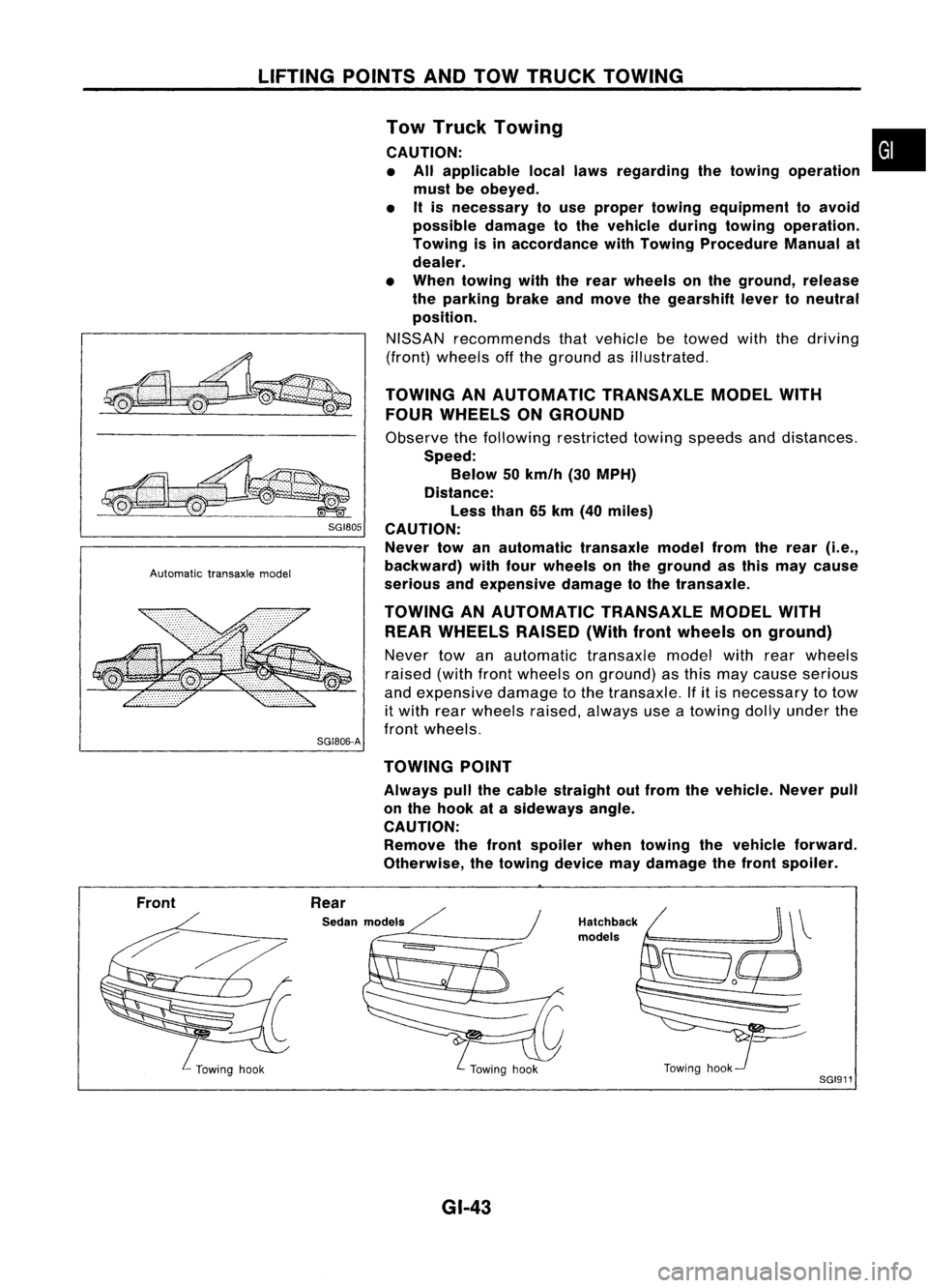
Truck Towing •
CAUTION: • All applicable locallawsregarding thetowing operation
must beobeyed.
• Itis necessary touse proper towing equipment toavoid
possible damagetothe vehicle duringtowing operation.
Towing isinaccordance withTowing Procedure Manualat
dealer.
• When towing withtherear wheels onthe ground, release
the parking brakeandmove thegearshift levertoneutral
position.
NISSAN recommends thatvehicle betowed withthedriving
(front) wheels offthe ground asillustrated.
TOWING ANAUTOMATIC TRANSAXLEMODELWITH
FOUR WHEELS ONGROUND
Observe thefollowing restricted towingspeeds anddistances.
Speed: Below 50km/h (30MPH)
Distance: Less than65km (40 miles)
CAUTION: Never towanautomatic transaxlemodelfromtherear
(i.e.,
backward) withfourwheels onthe ground asthis may cause
serious andexpensive damagetothe transaxle.
TOWING ANAUTOMATIC TRANSAXLEMODELWITH
REAR WHEELS RAISED(Withfrontwheels onground)
Never towanautomatic transaxlemodelwithrearwheels
raised (withfrontwheels onground) asthis may cause serious
and expensive damagetothe transaxle. Ifitis necessary totow
it with rearwheels raised,always useatowing dollyunder the
front wheels.
TOWING POINT
Always pullthecable straight outfrom thevehicle. Neverpull
on the hook atasideways angle.
CAUTION: Remove thefront spoiler whentowing thevehicle forward.
Otherwise, thetowing devicemaydamage thefront spoiler.
Front Rear
Sedan models
GI-43
Hatchback
models
Towinghook
SGI911
Page 1448 of 1701
TROUBLEDIAGNOSES
Wiring Diagram -
A/C -
(Cont'd)
GA engine AfTmodels -for Europe LHDwithout daytime lightsystem (withdealer installed
towing kit)
HA-A/C-09
BATTERY (Via
fusible link)
t
COOLING
FAN
MOTOR-2
~
•
I
GIS
G/Y
ID
$-$@g)
GIS
G/Y
mrn
La Hi
1+) 1+)
-
COOLING
FAN
MOTOR-1
Hi La~ HiLa
H H~ HH
IkjJJ ~ ~~
LG/S S
@D
LG/SS~
IrjJ~ -
$
66
IrjJ~-
i$/
6
LG/S S
@
LG/SS
ID
I-I
&-_I!__~.,
S S
~ ~
~~
SR
GYLG/S
~ ~RELAY-2
~~~rn> LG
G/Y
S
I '
-
.
i
I
T-
GIS G/Y@
IciJ~ -
t~J1@D
GIS G/Y
mm
La Hi
1+) (+)
Refer
toEL-POWER.
I
ECM
(ECCS
CONTROL
MODULE)
em
FUSE
BLOCK 30A
(JIB)
r-e-t
(El06) ~
IQ;OI
GY
BR _
1_
f-p:=_e:::::-
BR GY
1:Jt1 :lJIICOOLING
n
FAN
U
RELAY-1
IbjJJ
ILi=U
LG/R G/B
I
LG/R~ LG
~\EJQ!I ~
~M8----------~
Li~
I
LG/R~ LG
Iqp~-~~---------~qpl
LG/R
CEID
LG
m
ffiJl
2
RFRL RFRL
¥
@
2 1L
5
rffi\
@ID,
@?),
(f303), ~
t:]JY
GYGYGY GY
"2
57
@
36 SR
Refer
tolast page
(Foldout page).
CHID,
(El06)
em
@
W
HHA047
HA-46
Page 1495 of 1701

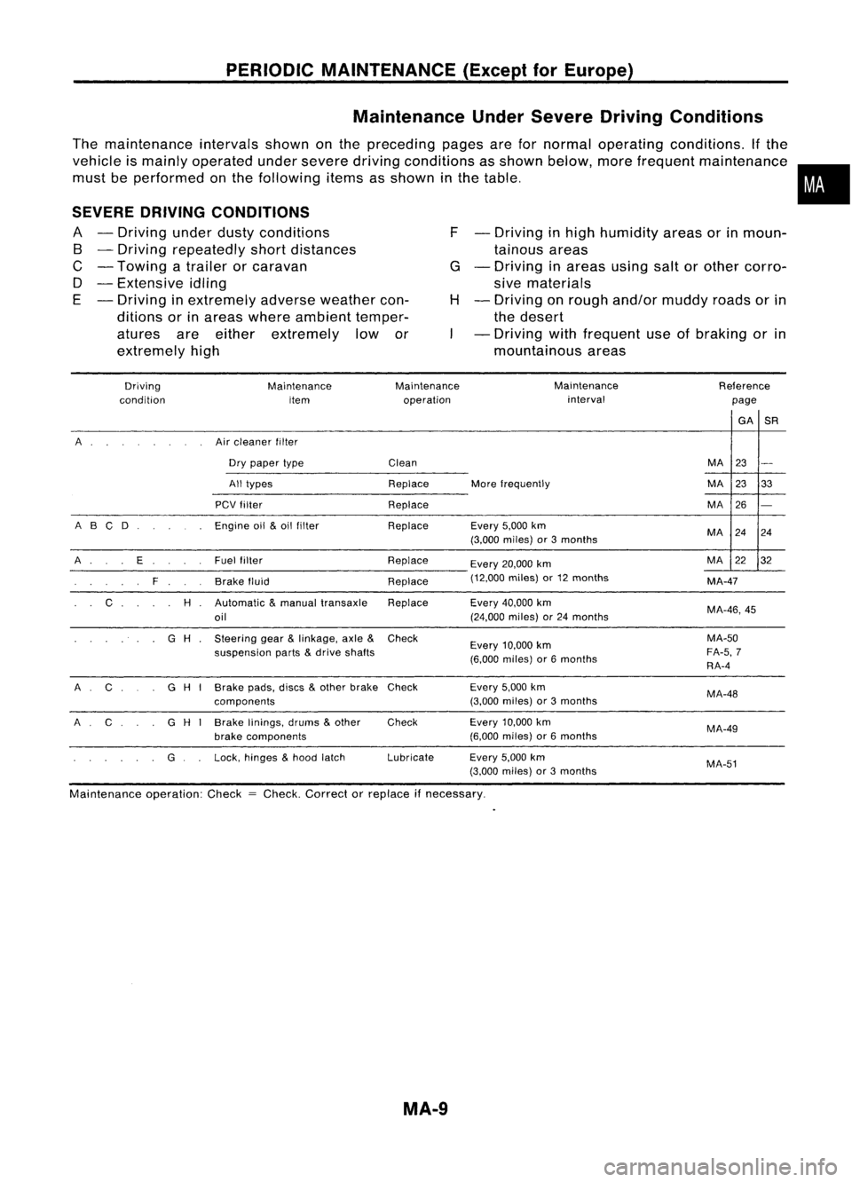
PERIODICMAINTENANCE (ExceptforEurope)
Maintenance UnderSevere DrivingConditions
The maintenance intervalsshownonthe preceding pagesarefornormal operating conditions. Ifthe
vehicle ismainly operated undersevere drivingconditions asshown below, morefrequent maintenance •
must beperformed onthe following itemsasshown inthe table. •
SEVERE DRIVING CONDITIONS
A -Driving underdustyconditions
B -Driving repeatedly shortdistances
C -Towing atrailer orcaravan
D -Extensive idling
E -Driving inextremely adverseweather con-
ditions orinareas where ambient temper-
atures areeither extremely lowor
extremely high F
-Driving inhigh humidity areasorinmoun-
tainous areas
G -Driving inareas usingsaltorother corro-
sive materials
H -Driving onrough and/or muddy roadsorin
the desert
- Driving withfrequent useofbraking orin
mountainous areas
Driving
condition Maintenance
item Maintenance
operation Maintenance
interval Reference
page
GA
SR
A Aircleaner filter
Dry paper type
Clean MA
23
-
All types ReplaceMorefrequently MA
2333
PCV filter Replace MA26
-
A BC D
Engineoil
&
oil filter ReplaceEvery
5,000km
MA2424
(3,000 miles) or3months
A E Fuel
filter Replace
Every20,000 km MA
2232
F Brakefluid Replace(12,000
miles)or12 months
MA-47
C
H
Automatic
&
manual transaxle Replace Every40,000 km
MA-46,45
oil (24,000
miles)or24 months
G
H
Steering
gear
&
linkage, axle
&
Check
Every10,000 km MA-50
suspension parts
&
drive shafts
(6,000miles) or6months FA-5,
7
RA-4
A C G
H
I
Brake pads,discs
&
other brake Check Every
5,000km
MA-48
components (3,000
miles) or3months
A C
G
H
1
Brake
linings, drums
&
other
Check Every
10,000 km
MA-49
brake components (6,000
miles) or6months
G Lock,
hinges
&
hood latch Lubricate
Every5,000km
MA-51
(3,000 miles) or3months
Maintenance operation:Check
=
Check. Correct orreplace
if
necessary.
MA-9