Page 256 of 1701
SEAT
Heated Seat
• When handling seat,beextremely carefulnottoscratch heating unit.
• Toreplace heatingunit,seattrimandpadshould beseparated.
• Donot use anyorganic solvent, suchasthinner, benzene, alcohol,gasoline, etc.toclean trims.
Seatback heatingunitremoval
&
installation
Heating
unit Seat
back trim
Trim temperature Increasing
to
Decreasing to
0C (OF) 35
-45
15-25
(95 -113)
(59-77)
Thermostat OFFON
operation
SBF424H
* For Wiring Diagram, referto"HEATED SEAT"inEL section.
8T-36
Page 1175 of 1701

ENGINECOOLING SYSTEM
I
GA, SR,CD
I
Radiator (Aluminum type)
r
Sealing rubber~
•
SLC882AB
AIT
model only
r
Upper tank
Sealing rubber~
/"""-.
CJ~~ /~.........."-. '-.. ....,
1I
. / -~ '-""", /~Oil coolersecuring nut-
~ ~,>" (
6<,~8 •
12 N.m
(0.8•1.2 kg-m,
69-104
In-Ib)
@
0..~
~>..
!--Conicalwasher~
, ~I"~"-
Washer
/ /~, ,-O-ring~
Lower tank
-.I
I/' ,_
Oil cooler
o
,
SEC.
214
1.5(0.059)
H"
=
7.6
(0.299)
Unit: mm(in)
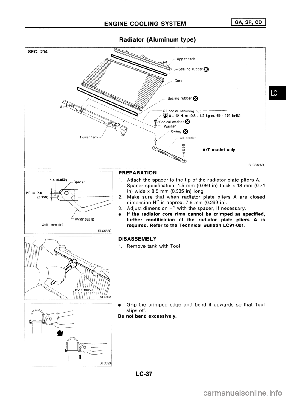
PREPARATION
1. Attach thespacer tothe tipofthe radiator platepliers A.
Spacer specification: 1.5mm (0.059 in)thick x18 mm (0.71
in) wide x8.5 mm (0.335 in)long.
2. Make surethatwhen radiator platepliers Aare closed
dimension H"isapprox. 7.6mm (0.299 in).
3. Adjust dimension H"with thespacer, ifnecessary.
• Ifthe radiator corerimscannot becrimped asspecified,
further modification ofthe radiator platepliers Ais
required. Refertothe Technical BulletinLC91-001.
SLC655C
D1SASSEMBL Y
1. Remove tankwithTool.
• Grip thecrimped edgeandbend itupwards sothat Tool
slips off.
Do not bend excessively.
*
LC-37
Page 1491 of 1701

PRE-DELIVERYINSPECTIONITEMS
Shown belowarePre-delivery InspectionItemsrequired forthe new vehicle. Itis recommended that
necessary itemsotherthanthose listedherebeadded, payingdueregard tothe conditions ineach
country.
Perform applicable itemsoneach model. Consult textofthis section forspecifications .
UNDER HOOD-engine off
o
Radiator coolantlevelandcoolant hosecon-
nections forleaks
o
Battery fluidlevel, specific gravityandcondi-
tions ofbattery terminals
o
Drive beltstension
D
Fuel filter forwater ordusts, andfuel lines
and connections forleaks
[] Engine oillevel andoilleaks
D
Clutch andbrake reservoir fluidlevel and
fluid lines forleaks
o
Windshield andrear window washerand
headlamp cleanerreservoir fluidlevel
D
Power steering reservoir fluidlevel andhose
connections forleaks
ON INSIDE ANDOUTSIDE
D
Remove frontspring/strut spacer(Ifapplica-
ble)
D
Operation ofall instruments, gauges,lights
and accessories
o
Operation ofhorn(s), wiperandwasher
[] Steering lockforoperation
[] Check airconditioner forgas leaks
o
Front andrear seats, andseat belts foroper-
ation
n
All moldings, trimsandfittings forfitand
alignment
[J
Allwindows foroperation andalignment
n
Hood, trunklid,door panels forfitand align-
ment
[1
Latches, keysandlocks foroperation
rl
Weatherstrips foradhesion andfit
[l
Headlamp aiming
I~ Tighten wheelnuts(Inc. inner nutsifapplica-
ble)
IJ Tire pressure (Inc.spare tire)
Il
Check frontwheels fortoe-in
IJ Install clock/voltmeter/room lampfuse(If
applicable)
~ Install deodorizing filtertoair purifier (If
applicable)
~ Remove wiperbladeprotectors (Ifapplicable)
UNDER
BODY
o
Manual transmission/transaxle, transferand
differential gearoillevel
D
Brake andfuel lines andoil/fluid reservoirs
for leaks
D
Tighten boltsandnuts ofsteering linkageand
gear box,suspension, propellershaftsand
drive shafts
~ Tighten rearbody boltsandnuts (Models with
wooden bedonly)
ROAD TEST
D
Clutch operation
D
Parking brakeoperation
[J
Service brakeoperation
D
Automatic transmission/transaxle shifttiming
and kickdown
[] Steering controlandreturnability
o
Engine performance
D
Squeaks andrattles
ENGINE OPERATING ANDHOT
D
Adjust idlemixture andspeed (andignition
timing*1)
n
Automatic transmission/transaxle fluidlevel
~ Engine idlingandstop knob operation (Diesel
only)
FINAL INSPECTION
n
Install necessary parts(outside mirror,wheel
covers, seatbelts, mat,carpet ormud flaps)
[1
Inspect forinterior andexterior metaland
paint damage
[] Check forspare tire,jack, tools (wheel
chock), andliterature
n
Wash, cleaninterior andexterior
"1: Not required onmodels withadirect ignition system
~ :Not appiicable tothis model.
•
MA-5
Page 1643 of 1701

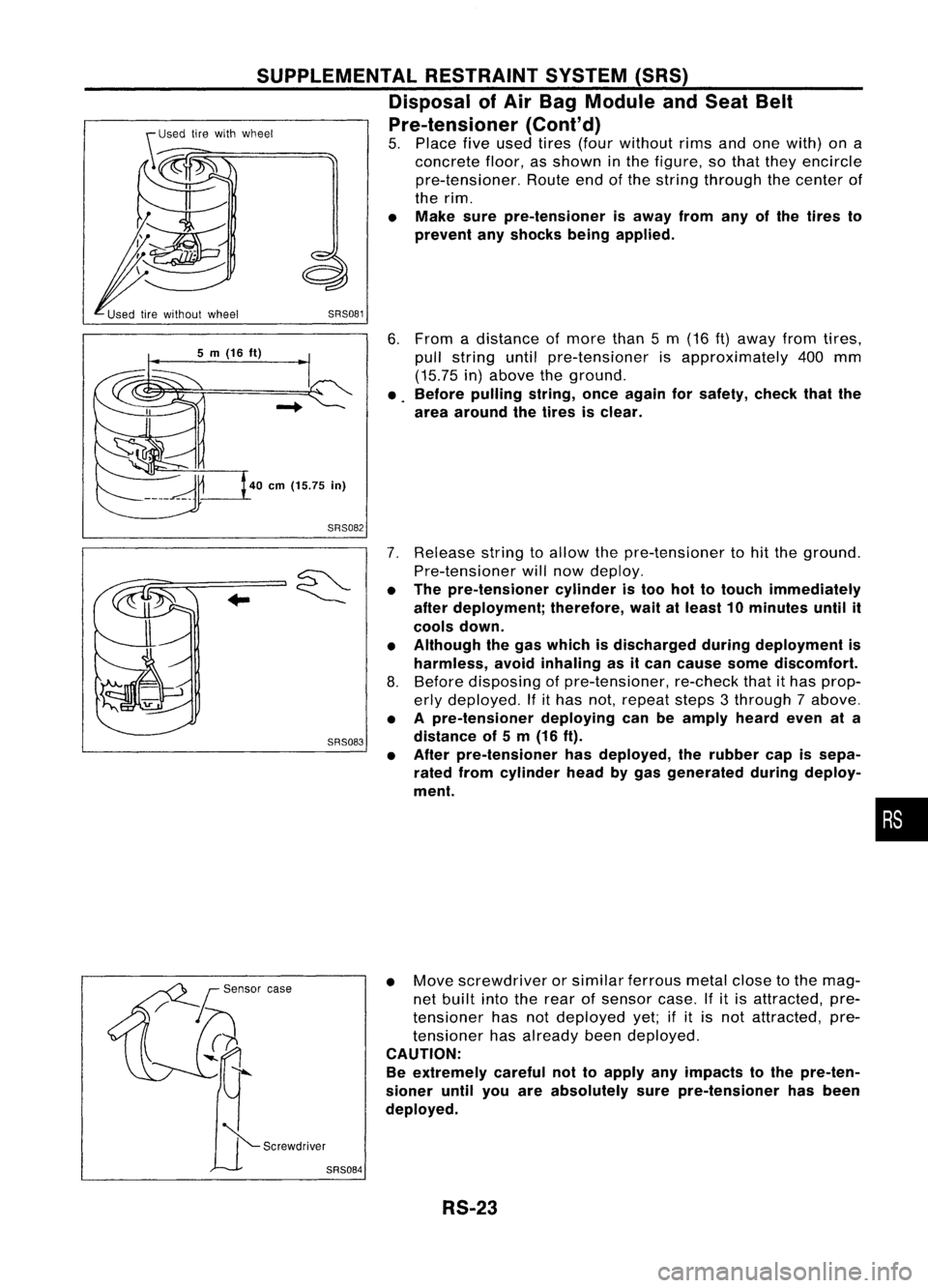
6.From adistance ofmore than5m (16
ft)
away fromtires,
pull string untilpre-tensioner isapproximately 400mm
(15.75 in)above theground.
• Before pulling string,onceagain forsafety, checkthatthe
area around thetires isclear.
SRS081
SUPPLEMENTAL
RESTRAINTSYSTEM(SRS)
Disposal ofAir Bag Module andSeat Belt
Pre-tensioner (Cont'd)
5. Place fiveused tires(four without rimsandonewith) ona
concrete floor,asshown inthe figure, sothat they encircle
pre-tensioner. Routeendofthe string through thecenter of
the rim.
• Make surepre-tensioner isaway fromanyofthe tires to
prevent anyshocks beingapplied.
40
em
(15.75
in)
5
m
(16
ft)
SRS082
SRS083
7.
Release stringtoallow thepre-tensioner tohit the ground.
Pre-tensioner willnow deploy.
• The pre-tensioner cylinderistoo hottotouch immediately
after deployment; therefore,waitatleast 10minutes untilit
cools down.
• Although thegas which isdischarged duringdeployment is
harmless, avoidinhaling asitcan cause somediscomfort.
8. Before disposing ofpre-tensioner, re-checkthatithas prop-
erly deployed. Ifithas not,repeat steps3through 7above.
• Apre-tensioner deployingcanbeamply heardevenata
distance of5m (16 ft).
• After pre-tensioner hasdeployed, therubber capissepa-
rated fromcylinder headbygas generated duringdeploy-
ment.
•
• Move screwdriver orsimilar ferrous metalclosetothe mag-
net built intotherear ofsensor case.Ifitis attracted, pre-
tensioner hasnotdeployed yet;ifit is not attracted, pre-
tensioner hasalready beendeployed.
CAUTION:
Be extremely carefulnottoapply anyimpacts tothe pre-ten-
sioner untilyouareabsolutely surepre-tensioner hasbeen
deployed.
RS-23