Page 988 of 1701
![NISSAN ALMERA N15 1995 Service Manual TROUBLEDIAGNOSIS -General Description
ill]
Diagnostic TroubleCode(DTC) Chart(Cont'd)
x:
Applicable
-: Not applicable
"DTC *1
*2
Check Items CONFIRMATION
"OVERALLFUNC-
Fail ReferencePag NISSAN ALMERA N15 1995 Service Manual TROUBLEDIAGNOSIS -General Description
ill]
Diagnostic TroubleCode(DTC) Chart(Cont'd)
x:
Applicable
-: Not applicable
"DTC *1
*2
Check Items CONFIRMATION
"OVERALLFUNC-
Fail ReferencePag](/manual-img/5/57349/w960_57349-987.png)
TROUBLEDIAGNOSIS -General Description
ill]
Diagnostic TroubleCode(DTC) Chart(Cont'd)
x:
Applicable
-: Not applicable
"DTC *1
*2
Check Items CONFIRMATION
"OVERALLFUNC-
Fail ReferencePage
(Possible Cause) PROCEDURE"
TIONCHECK"
Safe
Quick Ref. QuickRef. System
• Harness orconnectors
(The sensor circuitisopen orshorted.)
• Camshaft positionsensor
RUNNING
--
EC-289
• Starter motor
• Starting systemcircuit(ELsection)
• Dead (Weak) battery
• Harness orconnectors
-
(The sensor circuitisopen orshorted.) RUNNING
RUNNING
X
EC-293
• Mass airflow sensor
• Harness orconnectors
(The sensor circuitisopen orshorted.) IGN:
ON
-
X
EC-297
• Engine coolant temperature sensor
• Harness orconnectors
(The ignition primary circuitisopen orshorted.)
• Power transistor unit RUNNING
--
EC-301
• Camshaft positionsensor
• Camshaft positionsensorcircuit
• Harness orconnectors
(The sensor circuitisopen orshorted.) RUNNING
--
EC-306
• Knock sensor
• Harness orconnectors
(The sensor circuitisopen orshorted.)
-
IGN:
ON
X
EC-309
• Throttle position sensor
• No failure
--
-
-
*2: •The "OVERALL FUNCTIONCHECK"isasimplified andeffective waytoinspect acomponent orcircuit.
In some cases, the"OVERALL FUNCTIONCHECK"isused rather thana"DIAGNOSTIC TROUBLECODECONFIRMA-
TION PROCEDURE".
When noDTC CONFIRMATION PROCEDUREisavailable, the"NG" result ofthe OVERALL FUNCTION CHECKcanbe
considered tomean thesame asaDTC detection .
• During an"NG" OVERALL FUNCTION CHECK,theDTC might notbeconfirmed.
EC-269
•
Page 993 of 1701

TROUBLEDIAGNOSIS -General Description
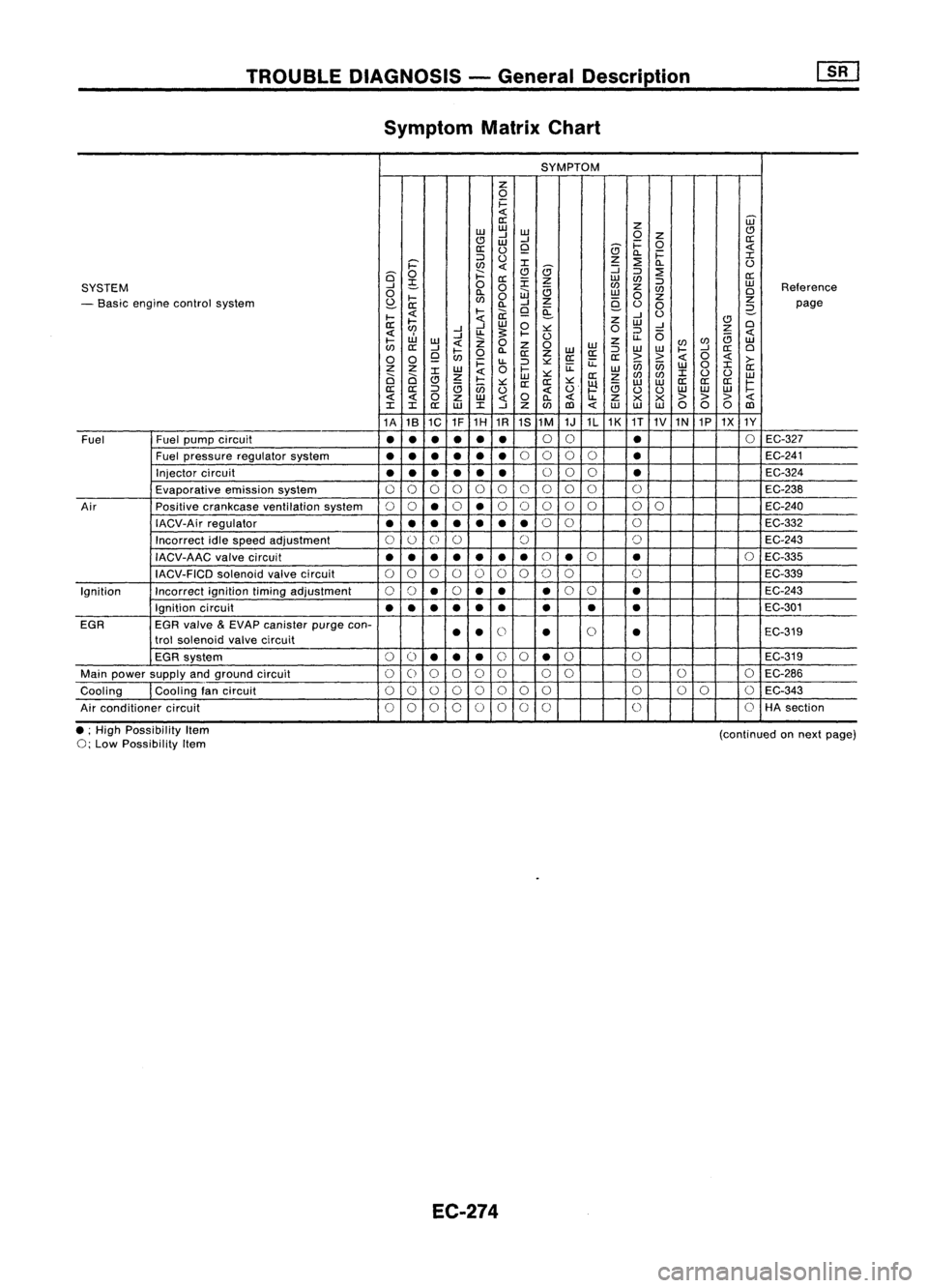
Symptom MatrixChart
SYMPTOM
z
0
i=
0::
Z
ill
w w
w
(!)
(!J
-l
-l
0
Z
0::
W
i=
0
0::
0
Q
(9
c..
i=
::>
0
z
::2:
:r:
i='
l/)
:r:
(9
:J
c..
0
6'
0
j::::
Q
::>
::2:
0::
;S
0
0::
:r:
z
w
l/)
::>
w
SYSTEM
....J
0
a
l/)
z
l/)
Reference
0
l-
e..
0
iJJ
w
0
z
0
- Basic engine control system
S?-
l/)
-l
Z
9-
z
0::
c..
Q ~
0
0
2-
page
I-
l-
ii:
....J
0
II:
I-
w
0
z
w
(!)
0
l/)
....J....J
~
:>:::
0
::>
-l
z
uJ
....J
U.
I-
0
U.
(5
B
I-
W
Z
0
z
l/)
w
l/)
II:
....J
Z
0
W
WW
l/)
....J
II:
0
I-
0
c..
II:
Z
W
II:
::>
I-
0
0
Q
l/)
II:II:
>>
0
i=
u.
::>
:>:::
u::
ii5ii5
w
0
:r:
>-
z z
w
0
I-
u::
W
II:
0 0
:r:
z
w
:>:::
II:
z
l/)
l/)
:r:
0 0
w
(!J
I-
:>:::
II: II:
:>:::
~
w
W
II:
II: II:
r:
II:
II:
::>
B
ii5
0
O'
B
00
w
w w
0
z
w
0
c..
u..
Z
><><
>
> >
:r: :r:
II:
w
:r:
-l
z
l/)
co
W
WW
00 0
co
1A 181C 1F1H
1R
1S1M
1J1L1K
1T
1V1N 1P1X 1Y
Fuel Fuelpump circuit
•
•
•
•
•
•
0
0
•
0
EC-327
Fuel pressure regulatorsystem
•
••
•
••
0
0 00
•
EC-241
Injector circuit
••
•
• •
•
0
00
•
EC-324
Evaporative emissionsystem
00 0 00
0 0
0
0
0 0
EC-238
Air Positivecrankcase ventilation system
00
•
0
•
0
0 0
0
0
00
EC-240
IACV-Air regulator
•••
•
••
•
0
0
0
EC-332
Incorrect idlespeed adjustment
0
0
0
0 0 0
EC-243
IACV-AAC valvecircuit
••
•
•
•
•
•
0
•
0
•
0
EC-335
IACV-FICD solenoidvalvecircuit
0
0 0
000 00 0
C)
EC-339
Ignition Incorrectignitiontimingadjustment
00
•
0
•• •
0
0
•
EC-243
Ignition circuit
•
•
•
•
•
•
• •
•
EC-301
EGR EGRvalve
&
EVAP canister purgecon-
00
trol solenoid valvecircuit
•
•
•
•
EC-319
EGR system
0
()
•• •
0
0
•
0
0
EC-319
Main power supply andground circuit
00 0 0
C)
0 00
0
0
0
EC-286
Cooling Coolingfancircuit
0
0
0
00 00 0 000 0
EC-343
Air conditioner circuit
00 00 0
00
0 0
0
HA
section
• ;High Possibility Item
0;
Low Possibility Item
EC-274
(continued
onnext page)
Page 1020 of 1701

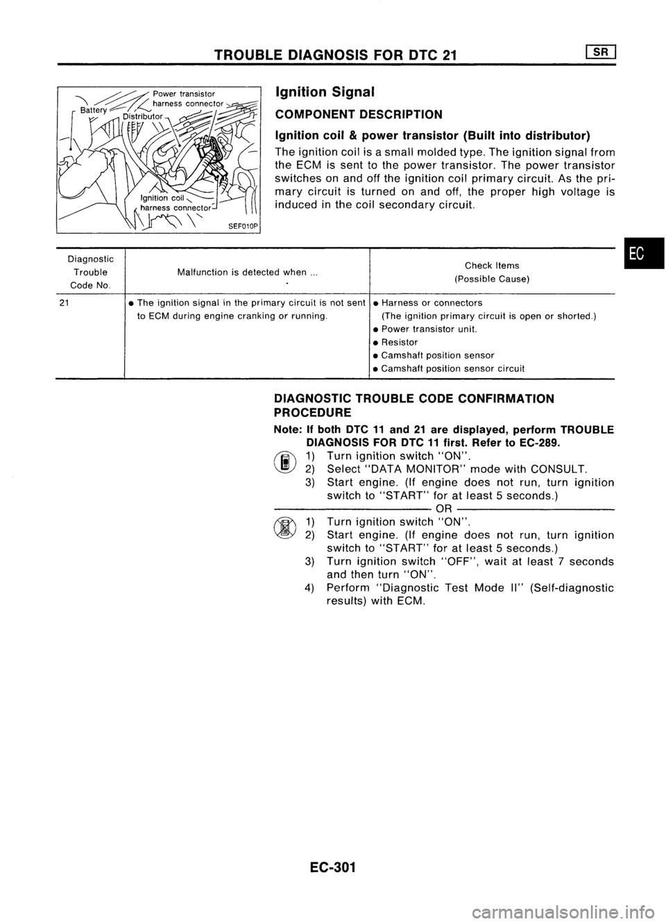
TROUBLEDIAGNOSIS FORDTC21
Ignition Signal
COMPONENT DESCRIPTION
Ignition coil
&
power transistor (Builtintodistributor)
The ignition coilisasmall molded type.Theignition signalfrom
the ECM issent tothe power transistor. Thepower transistor
switches onand offthe ignition coilprimary circuit.Asthe pri-
mary circuit isturned onand off,the proper highvoltage is
induced inthe coil secondary circuit.
Diagnostic Trouble
Code No.
21
Malfunction
isdetected when...
• The ignition signalinthe primary circuitisnot sent
to ECM during engine cranking orrunning. Check
Items
(Possible Cause)
• Harness orconnectors
(The ignition primary circuitisopen orshorted.)
• Power transistor unit.
• Resistor
• Camshaft positionsensor
• Camshaft positionsensorcircuit
•
DIAGNOSTIC TROUBLECODECONFIRMATION
PROCEDURE
Note: Ifboth DTC11and 21are displayed, performTROUBLE
DIAGNOSIS FORDTC11first. Refer toEC-289.
(F.I\ 1)Turn ignition switch"ON".
~ 2)Select "DATA MONITOR" modewithCONSULT.
3) Start engine. (Ifengine doesnotrun, turn ignition
switch to"START" foratleast 5seconds.)
---------- OR----------
~ 1)Turn ignition switch"ON".
~ 2)Start engine. (Ifengine doesnotrun, turn ignition
switch to"START" foratleast 5seconds.)
3) Turn ignition switch"OFF", waitatleast 7seconds
and then turn"ON".
4) Perform "Diagnostic TestMode II"(Self-diagnostic
results) withECM.
EC-301