1995 NISSAN ALMERA N15 electric
[x] Cancel search: electricPage 1 of 1701

AUTOMATICTRANSAXLE
SECTION
AT
CONTENTS
PREPARATION ANDPRECAUTIONS
3
Special Service Tools 3
Commercial ServiceTools 6
Service Notice 7
Supplemental RestraintSystem(SRS)"AIR
BAG" (DualAirBag System) 7
Supplemental RestraintSystem(SRS)"AIR
BAG" (Single AirBag System) 7
DESCRIPTION
8
Cross-sectional View 8
Hydraulic ControlCircuit 10
Shift Mechanism 14
Control System 15
TROUBLE DIAGNOSES 17
Preliminary Check(PriortoRoad Testing) 17
Road Testing 17
Stall Tasting 24
Pressure Testing 26
Wiring Diagram -AT - 28
Electrical Components Inspection 30
ON-VEHICLE SERVICE 31
Control ValveAssembly andAccumulator 31
Throttle WireAdjustment.. 33
Control CableInstallation andAdjustment 35
Governor Valve 36
Inhibitor SwitchAdjustment 37
Differential SideOilSeal Replacement.. 37
REMOVAL ANDINSTALLATION
39
Removal 39
Installation .40MAJOR
OVERHAUL.. 42
All Models 42
Except Model34X81 .44
Model 34X81 45•
Shift Control Components 46
i
Oil Channel 47
Locations ofAdjusting Shims,Needle
Bearings, ThrustWashers andSnap Rings -
Except Model34X81 .48
Locations ofAdjusting Shims,Needle
Bearings, ThrustWashers andSnap Rings -
Model 34X81 .49
DiSASSEMBLy 50
REPAIR FORCOMPONENT PARTS 66
Manual ShaftandThrottle Lever 66
Oil Pump 70
Control ValveAssembly 74
Control ValveUpper Body 86
Control ValveLower Body 90
Reverse Clutch 93
High Clutch 97
Forward ClutchandOverrun Clutch 102
Low &Reverse Brake 108
Rear Internal Gear,Forward ClutchHuband
Overrun ClutchHub 112
Output Shaft,Output Gear,IdlerGear,
Reduction PinionGearandBearing Retainer
- Except Model34X81 116
Output Shaft,IdlerGear, Reduction Pinion
Gear andBearing Retainer -Model 34X81 121
Band Servo Piston Assembly 126
Final Drive -Except Model34X81 131
Final Drive -Model 34X81 135
Page 7 of 1701

PREPARATIONANDPRECAUTIONS
Service Notice
Supplemental RestraintSystem(SRS)"AIR
BAG" (DualAirBag System)
The Supplemental RestraintSystem"AirBag" usedalong withaseat belt, helps toreduce therisk or
severity ofinjury tothe driver andfront passenger inafrontal collision. TheSupplemental Restraint
System consists ofair bag modules (locatedinthe center ofthe steering wheelandonthe instrument
panel onthe passenger side),adiagnosis sensorunit,warning lamp,wiring harness andspiral cable.
Information necessarytoservice thesystem safelyisincluded inthe
RSsection
ofthis Service Manual.
WARNING:
• Toavoid rendering theSRS inoperative, whichcouldincrease therisk ofpersonal injuryordeath
in the event ofacollision whichwould resultinair bag inflation, allmaintenance mustbeperformed
by an authorized NISSANdealer.
• Improper maintenance, includingincorrectremovalandinstallation ofthe SRS, canlead topersonal
injury caused byunintentional activationofthe system.
Ii
Donot use electrical testequipment onany circuit related tothe SRS unless instructed tointhis
Service Manual. SRSwiring harnesses arecovered withyellow insulation eitherjustbefore the
harness connectors orfor the complete harness,foreasy identification.
•
Before proceeding withdisassembly, thor-
oughly cleantheoutside ofthe transaxle. Itis
important toprevent theinternal partsfrom
becoming contaminated bydirt orother for-
eign matter.
• Disassembly shouldbedone inaclean work
area.
• Use lint-free clothortowels forwiping parts
clean. Common shopragscanleave fibers
that could interfere withtheoperation ofthe
transaxle.
• Place disassembled partsinorder, onaparts
rack, foreasier andproper assembly.
• Allparts should becarefully cleaned-witha
general purpose, non-flammable solvent
before inspection orreassembly.
• Gaskets, sealsandO-rings shouldbe
replaced anytime thetransaxle isdisassem-
bled.
• Itis very important toperform functional tests
whenever theyareindicated. •
The valve bodycontains precision partsand
requires extremecarewhen partsare
removed andserviced. Placedisassembled
valve bodyparts inorder, onaparts rack,for
easier andproper assembly. Carewillalso
prevent springs andsmall partsfrombecom-
ing scattered orlost.
• Properly installedvales,sleeves, plugs,etc.
will slide along theirbores inthe valve body
under theirownweight.
• Before assembly, applyacoat ofrecom-
mended ATFtoall parts. Apply petroleum
jelly toprotect O-ringandseals, orhold bear-
ings andwashers inplace during assembly.
Do not use grease.
• Extremely careshould betaken toavoid dam-
age toO-rings, sealsandgaskets when
assembling.
• After overhaul, refillthetransaxle withnew
ATF.
•
Supplemental RestraintSystem(SRS)"AIR
BAG" (Single AirBag System)
The Supplemental RestraintSystem"AirBag" andused along withaseat belt,helps toreduce therisk
or severity ofinjury tothe driver inafrontal collision. TheSupplemental RestraintSystemconsists of
an air bag module (located inthe center ofthe steering wheel),adiagnosis sensorunit,warning lamp,
wiring harness andspiral cable. Information necessarytoservice thesystem safelyisincluded inthe
RS section
ofthis Service Manual.
WARNING:
• Toavoid rendering theSRS inoperative, whichcouldincrease therisk ofpersonal injuryordeath
in the event ofacollision whichwould resultinair bag inflation, allmaintenance mustbeperformed
by an authorized NISSANdealer.
• Improper maintenance, includingincorrectremovalandinstallation ofthe SRS, canlead topersonal
injury caused byunintentional activationofthe system.
• Donot use electrical testequipment onany circuit related tothe SRS unless instructed tointhis
Service Manual.
AT-7
Page 15 of 1701
DESCRIPTION
Shift Mechanism (Cont'd)
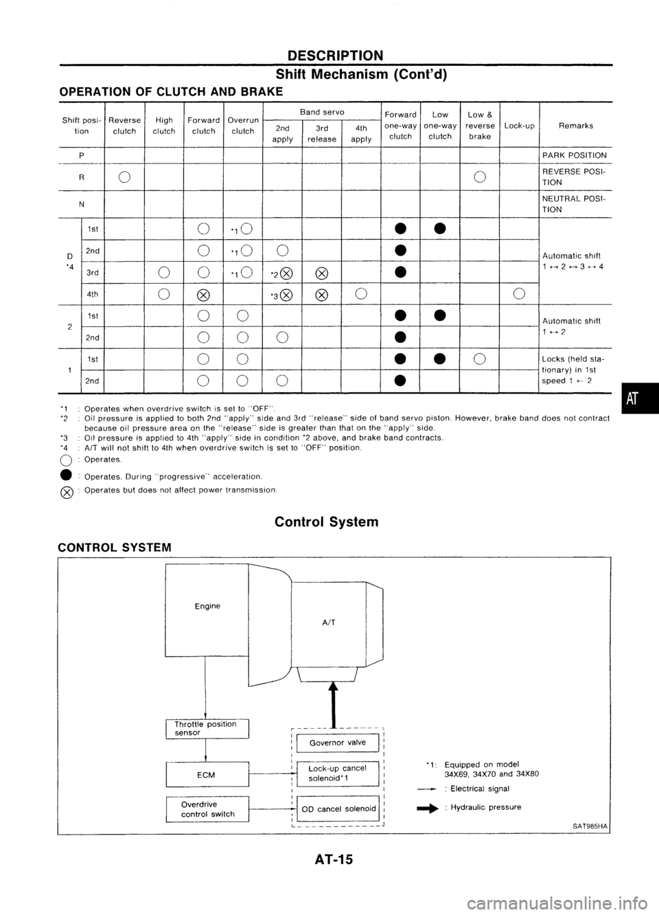
OPERATION OFCLUTCH ANDBRAKE
Bandservo
ForwardLow
Low
&
Shift posi- Reverse
HighForward
Overrun
Lock-upRemarks
tion clutch clutchclutchclutch 2nd
3rd4thone-way
one-way reverse
apply release
applyclutch
clutch brake
P PARK
POSITION
0 0REVERSE
POSI-
R TION
N NEUTRAL
POSI-
TION
1st 0'10
••
D 2nd
0'10
0
•
Automatic
shift
'4 00'10
'2@
@
•
1<-->2<-->3<-->4
3rd
4th 0@ '3@
@0
0
1st 00
••
Automatic
shift
2 1<-->2
2nd 00 0
•
1st 00
•
•
0
Locks
(heldsta-
1 tionary)
in1st
2nd 00 0
•
speed
1
<--
2
'1 Operates whenoverdrive switchissel to"OFF".
'2 Oilpressure isapplied toboth 2nd"apply" sideand3rd"release" sideofband servo piston. However, brakebanddoes notcontract
because oilpressure areaonthe "release" sideisgreater thanthatonthe "apply" side.
'3 Oilpressure isapplied to4th "apply" sideincondition '2above, andbrake bandcontracts.
'4 AIT
will notshift to4th when overdrive switchisset to"OFF" position.
o
Operates.
• Operates. During"progressive" acceleration.
@ Operates butdoes notaffect power transmission.
Control System
CONTROL SYSTEM
Engine
AIT
•
Lock-up cancel
solenoid'1
Overdrive
control switch
1:1
Governor valve
I
11
1
I
1
1
OD cancel solenoid :
; I
L
J
AT-15
'1:
Equipped onmodel
34X69, 34X70and34X80
: Electrical signal
.... :Hydraulic pressure
SAT985HA
Page 30 of 1701
TROUBLEDIAGNOSES
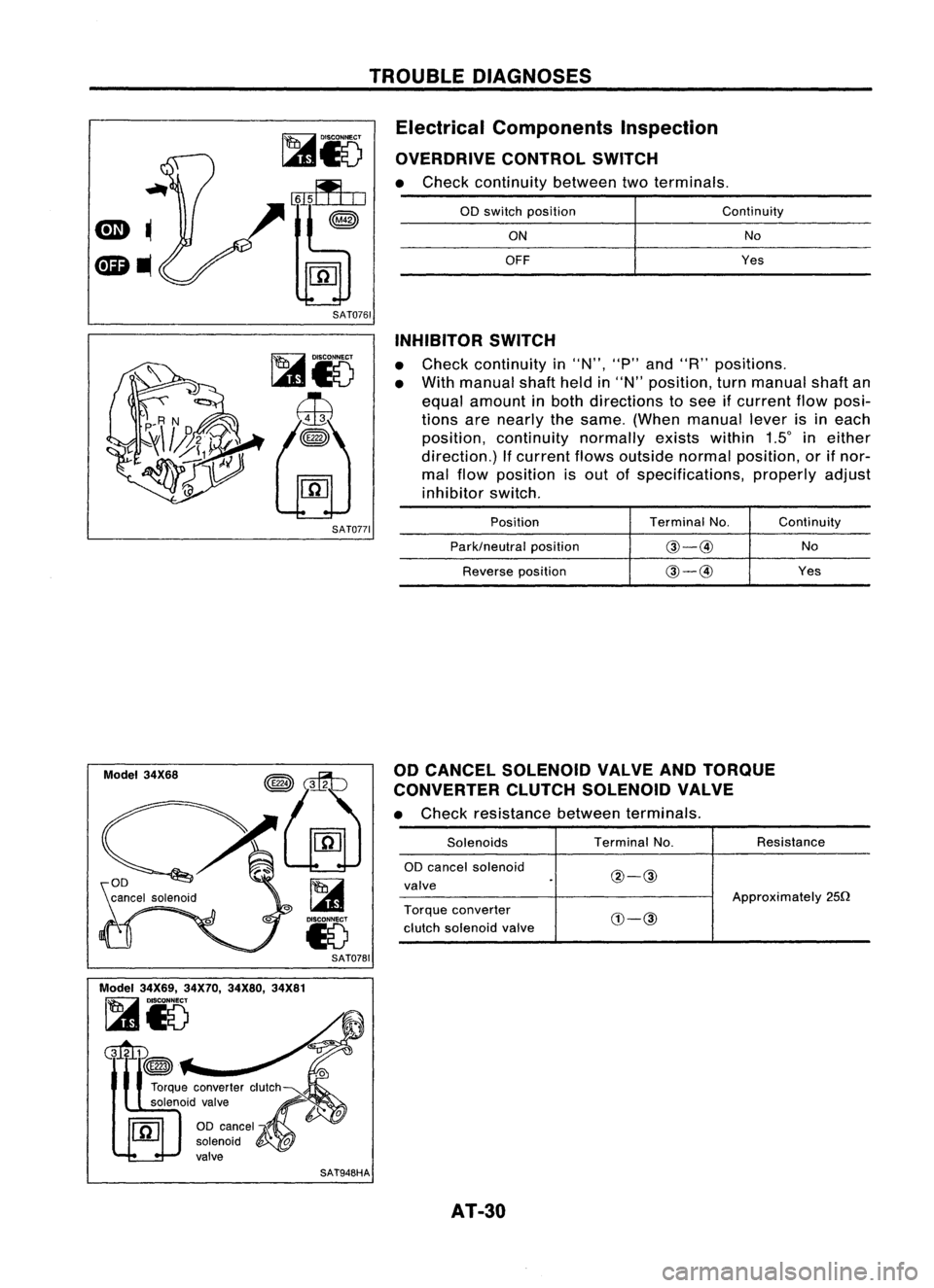
Electrical Components Inspection
OVERDRIVE CONTROLSWITCH
• Check continuity betweentwoterminals.
SAT0761
00
switch position
ON
OFF
Continuity
No
Yes
SAT0771
Model 34X68
SAT0781
Model 34X69, 34X70,34X80, 34X81
~i5
Gltm
~
SAT948HAINHIBITOR
SWITCH
• Check continuity in"N", "P"and "R" positions.
• With manual shaftheldin"N" position, turnmanual shaftan
equal amount inboth directions tosee ifcurrent flowposi-
tions arenearly thesame. (When manual leverisineach
position, continuity normallyexistswithin 1Sineither
direction.) Ifcurrent flowsoutside normalposition, orifnor-
mal flow position isout ofspecifications, properlyadjust
inhibitor switch.
Position TerminalNo. Continuity
Park/neutral position
@-@
No
Reverse position
@-@
Yes
00 CANCEL SOLENOID VALVEANDTORQUE
CONVERTER CLUTCHSOLENOID VALVE
• Check resistance betweenterminals.
Solenoids TerminalNo. Resistance
00 cancel solenoid
@-@
valve
Approximately250
Torque converter
CIJ-@
clutch solenoid valve
AT-30
Page 37 of 1701
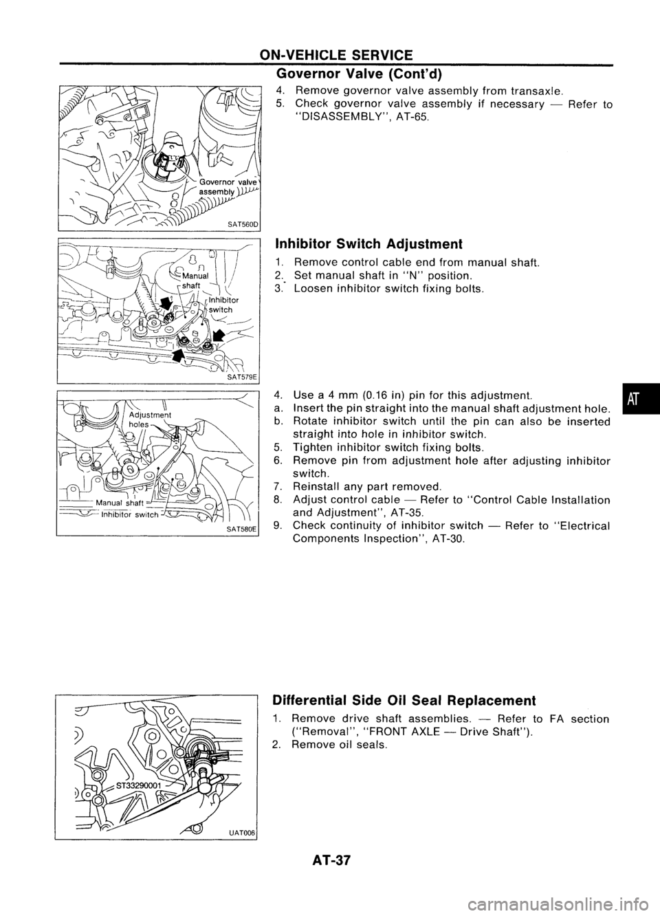
InhibitorSwitchAdjustment
1. Remove controlcableendfrom manual shaft.
2. Set manual shaftin"N" position.
3." Loosen inhibitor switchfixingbolts.
Use a4 mm (0.16 in)pin forthis adjustment. •
Insert thepinstraight intothemanual shaftadjustment hole.
Rotate inhibitor switchuntilthepincan also beinserted
straight intohole ininhibitor switch.
Tighten inhibitor switchfixingbolts.
Remove pinfrom adjustment holeafter adjusting inhibitor
switch.
Reinstall anypart removed.
Adjust control cable-Refer to"Control CableInstallation
and Adjustment", AT-35.
Check continuity ofinhibitor switch-Refer to"Electrical
Components Inspection",AT-30.
ON-VEHICLE
SERVICE
Governor Valve(Cont'd)
4. Remove governor valveassembly fromtransaxle.
5. Check governor valveassembly ifnecessary -Refer to
"DISASSEMBLY", AT-65.
4. a.b.
5.
6.
7.
8.
SAT580E 9.
Differential SideOilSeal Replacement
1. Remove driveshaftassemblies. -Refer toFA section
("Removal", "FRONTAXLE-Drive Shaft").
2. Remove oilseals.
AT-37
Page 41 of 1701

Boltlength
'T'
mm (in)
55 (2.17)
50 (1.97)
65 (2.56)
25 (0.98)
40 (1.57)
Tightening
torque
N'm (kg-m, ft-Ib)
70 -79 (7.1 -8.1,51 -59)
70 -79 (7.1 -8.1, 51-59)
70 -79 (7.1 -8.1,51 -59)
30 -40 (3.1 -4.1, 22-30)
30 -40 (3.1 -4.1, 22-30)
CD
@
@
@
@
Bolt
No.
• Reinstall anypart removed.
• Adjust throttle wireandcontrol cable.Referto"ON-VEHI-
CLE SERVICE", AT-33,35.
•. Check inhibitor switch.Referto"Electrical Components
Inspection", AT-3D.
• Refill transaxle withATFandcheck fluidlevel, AT-17.
• Move selector leverthrough allpositions tobe sure that
transaxle operatescorrectly. Withparking brakeapplied,
idle engine. Moreselector leverthrough "N"to"D", to"2",
to "1" and "R". Aslight shock should befelt through the
hand gripping theselector eachtimethetransaxle is
shifted. •
• Perform roadtest-Refer to"ROAD TESTING", AT-17.
i
REMOVAL
ANDINSTAllATION
Installation (Cont'd)
SR engine models
SAT638A
SAT558DA
AIT
toengine
@
Engine to
AIT
AT-41
Page 79 of 1701
REPAIRFORCOMPONENT PARTS
Control ValveAssembly (Cont'd)
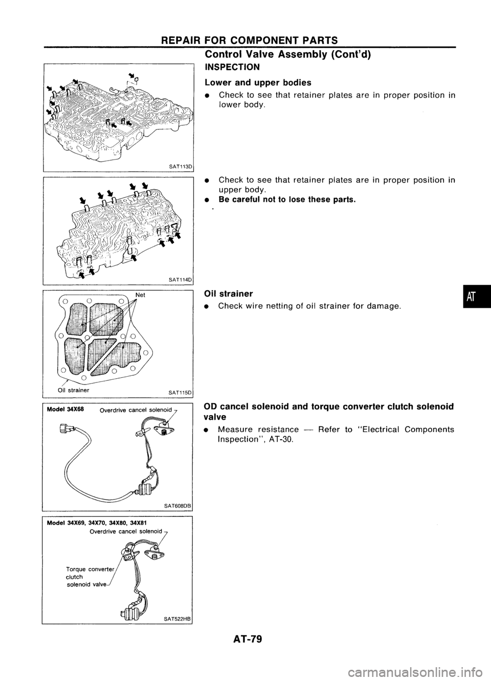
INSPECTION
Lower andupper bodies
• Check tosee that retainer platesareinproper position in
lower body.
SAT113D
•Check tosee that retainer platesareinproper position in
upper body.
• Becareful nottolose these parts.
Oil strainer
• Check wirenetting ofoil strainer fordamage.
•
Oil strainer
Model 34X68 SAT115D
Overdrive cancelsolenoid
SAT608DB 00
cancel solenoid andtorque converter clutchsolenoid
valve
• Measure resistance -Refer to"Electrical Components
Inspection", AT-3D.
Model 34X69, 34X70,34X80, 34X81
Overdrive cancelsolenoid
Torque converter
clutch solenoid valve
SAT522HBAT-79
Page 221 of 1701
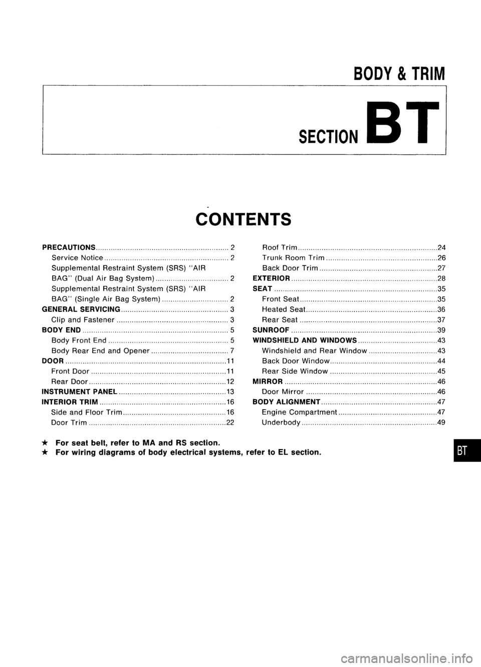
BODY
&
TRIM
SECTION
BT
CONTENTS
* For seat belt,refer toMA and RSsection.
* For wiring diagrams ofbody electrical systems,refertoEL section.
PRECAUTIONS
2
Service Notice 2
Supplemental RestraintSystem(SRS)"AIR
BAG" (DualAirBag System) 2
Supplemental RestraintSystem(SRS)"AIR
BAG" (Single AirBag System) 2
GENERAL SERViCiNG 3
Clip andFastener
3
BODY END
5
Body Front End
5
Body RearEndandOpener 7
DOOR 11
Front Door 11
Rear Door
12
INSTRUMENT PANEL
13
INTERIOR TRIM 16
Side andFloor Trim
16
Door Trim 22Roof
Trim 24
Trunk RoomTrim 26
Back DoorTrim 27
EXTERIOR 28
SEAT 35
Front Seat
35
Heated Seal... 36
Rear Seat 37
SUNROOF 39
WINDSHIELD ANDWINDOWS 43
Windshield andRear Window 43
Back DoorWindow 44
Rear SideWindow
.45
MIRROR 46
Door Mirror .46
BODY ALIGNMENT 47
Engine Compartment 47
Underbody .49
•