Page 397 of 1701
SEL711EBATTERY
CAUTION:
• If
itbecomes necessary tostart theengine withabooster
battery andjumper cables, usea12-volt booster battery.
• After connecting batterycables, ensurethatthey aretightly
clamped tobattery terminals forgood contact.
• Never adddistilled waterthrough thehole used tocheck
specific gravity.
How toHandle Battery
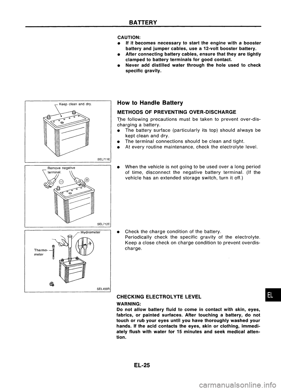
METHODS OFPREVENTING OVER-DISCHARGE
T.he following precautions mustbetaken toprevent over-dis-
charging abattery.
• The battery surface (particularly itstop) should always be
kept clean anddry.
• The terminal connections shouldbeclean andtight.
• Atevery routine maintenance, checktheelectrolyte level.
SEL459R
•
When thevehicle isnot going tobe used overalong period
of time, disconnect thenegative batteryterminal. (Ifthe
vehicle hasanextended storageswitch,turnitoff.)
• Check thecharge condition ofthe battery.
Periodically checkthespecific gravityofthe electrolyte.
Keep aclose check oncharge condition toprevent overdis-
charge.
CHECKING ELECTROLVTELEVEL •
WARNING: Do not allow battery fluidtocome incontact withskin, eyes,
fabrics, orpainted surfaces. Aftertouching abattery, donot
touch orrub your eyes untilyouhave thoroughly washedyour
hands. Ifthe acid contacts theeyes, skinorclothing, immedi-
ately flush withwater for15minutes andseek medical atten-
tion.
EL-25
Page 760 of 1701
•
oxygen
sen-
Europe and
nd Australia
els)
sensor
for Europe
el, and Aus-
T models)
@
II
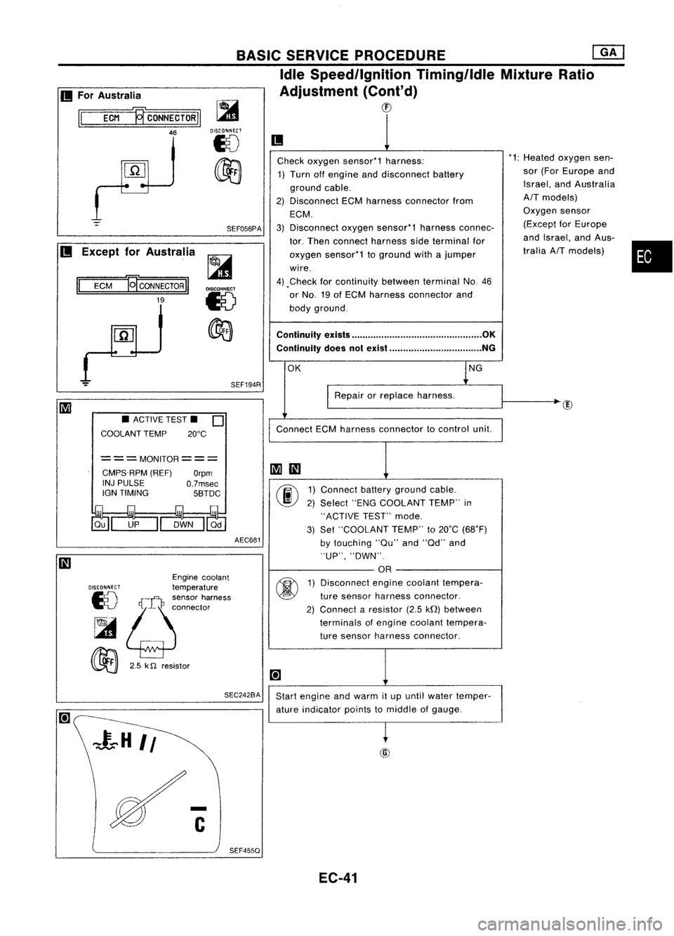
Check oxygen sensor*1 harness: *1:
Heated
1) Turn offengine anddisconnect battery sor
(For
ground cable. Israel,
a
2) Disconnect ECMharness connector from
AIT
mod
ECM. Oxygen
3) Disconnect oxygensensor*1 harnessconnec- (Except
tor. Then connect harness sideterminal for and
Isra
oxygen sensor*1 toground withajumper tralia
AI
wire.
4) .Check forcontinuity betweenterminalNo.46
or No. 19ofECM harness connector and
body ground.
Continuity exists................................................ OK
Continuity doesnotexist .................................. NG
OK lNG
I
Repair orreplace harness.
Connect ECMharness connector tocontrol unit.
~
III
00
1)
Connect batteryground cable.
2) Select "ENGCOOLANT TEMP"in
"ACTIVE TEST"mode.
3) Set "COOLANT TEMP"to20°C (68°F)
by touching "au"and"ad" and
"UP", "DWN".
OR
@
1)
Disconnect enginecoolant tempera-
ture sensor harness connector.
2) Connect aresistor (2.5kQ)between
terminals ofengine coolant tempera-
ture sensor harness connector.
[+]
Start engine andwarm itup until water temper-
ature indicator pointstomiddle ofgauge.
~
BASIC
SERVICE PROCEDURE ~
Idle Speed/Ignition Timing/IdleMixtureRatio
Adjustment (Cont'd)
CD
SEF194R
SEF056PA
~
DISCONNECT
18
~
AEC681
===MONITOR===
CMPS.RPM (REF)
Orpm
INJ PULSE
O.7msec
IGN TIMING 5BTDC
SEC242BA
•
ACTIVE TEST.
0
COOLANT TEMP 20°C
Engine coolant
DISCONNECT
temperature
10
!;j:~:~~'~";"'"
~
00
2.5k
n
resistor
II
ECM
19'
CONNECTOR
II
19
II
For Australia
II
ECM ~CONNECTORII
46
II
Except forAustralia
SEF455Q EC-41
Page 966 of 1701
![NISSAN ALMERA N15 1995 Service Manual Heatedoxygen sensor
harness connector BASIC
SERVICE PROCEDURE [][]
Idle Speed/Ignition Timing/IdleMixtureRatio
Adjustment (Cont'd)
@
II
MEF031DB
~io
ECM TIcoNNECTORl1
19
LEn
MEC712B
Check](/manual-img/5/57349/w960_57349-965.png "NISSAN ALMERA N15 1995 Service Manual Heatedoxygen sensor
harness connector BASIC
SERVICE PROCEDURE [][]
Idle Speed/Ignition Timing/IdleMixtureRatio
Adjustment (Cont'd)
@
II
MEF031DB
~io
ECM TIcoNNECTORl1
19
LEn
MEC712B
Check")
Heatedoxygen sensor
harness connector BASIC
SERVICE PROCEDURE [][]
Idle Speed/Ignition Timing/IdleMixtureRatio
Adjustment (Cont'd)
@
II
MEF031DB
~io
ECM TIcoNNECTORl1
19
LEn
MEC712B
Check
heated oxygen sensorharness:
1. Turn offengine anddisconnect batteryground
cable.
2. Disconnect ECMharness connector fromECM.
3. Disconnect heatedoxygen sensorharness con-
nector. Thenconnect harness sideterminal for
heated oxygen sensortoground withajumper
wire.
4. Check forcontinuity betweenterminal
@
ofECM
harness connector andbody ground.
Continuity exists OK
Continuity doesnotexist NG
OK
Repairorreplace harness.
Connect ECMharness connector toECM .
•
OR
1.
Connect batteryground cable.
2. Select "ENGCOOLANT TEMP"in
"ACTIVE TEST"mode.
3. Set "COOLANT TEMP"to20"C (68"F) by
touching "Qu"and"Qd" and"UP",
"DWN".
Disconnect enginecoolant temperature
sensor harness connector.
2. Connect aresistor (2.5kQ)between termi-
nals ofengine coolant temperature sensor
harness connector.
3. Connect batteryground cable.
Ii
AEC681
•
ACTIVE TEST.
0
COOLANT TEMP 20°C
===MONITOR=== CMPS.RPM (REF)
Orpm
INJ PULSE
O.7msec
IGN TIMING 5BTDC
DISCONNFCT
Enginecoolant
10 temperature
sensor
harness connector
~ ~
00
2.5
k0 resistor
Start
engine andwarm itup until engine coolant
temperature indicatorpointstomiddle ofgauge.
(Be sure tostart engine aftersetting "COOLANT
'-- A_E_C6_8-l2
TEMP"orinstalling a2.5 kQresistor.)
Ii
SEF455QEC-247
Page 1378 of 1701
HOWTOPERFORM EFFICIENT DIAGNOSIS FORANELECTRICAL INCIDENT
Circuit Inspection (Cont'd)
Voltage checkmethod
To help inunderstanding thediagnosis ofopen circuits pleaserefertothe previous schematic.
In any powered circuit,anopen canbefound bymethodically checkingthesystem forthe presence of
voltage. Thisisdone byswitching theDMM tothe voltage function.
1. Connect oneprobe ofthe DMM toaknown goodground.
2. Begin probing atone endofthe circuit andwork yourwaytothe other end.
3. With SW1open, probe atSW1 tocheck forvoltage.
voltage; openisfurther downthecircuit thanSW1.
no voltage; openisbetween fuseblock andSW1 (point A).
4. Close SW1andprobe atrelay.
voltage; openisfurther downthecircuit thantherelay.
no voltage; openisbetween SW1andrelay (point B).
5. Close therelay andprobe atthe solenoid.
voltage; openisfurther downthecircuit thanthesolenoid.
no voltage; openisbetween relayandsolenoid (pointC).
Any powered circuitcanbediagnosed usingtheapproach inthe above example.
SGI847
RELAY
~I SH~
SW2
c
1
(Resistance
check)
IGN "ON"
t
OR "S~:R.T~ '::~SEBLOCK
I I '-
SWl
I I
-=
B+SIOEl~~-:-~
~r-o~
SHORT SHORT
[YJ
DMMA B
+ -
(Voltage check)
TESTING
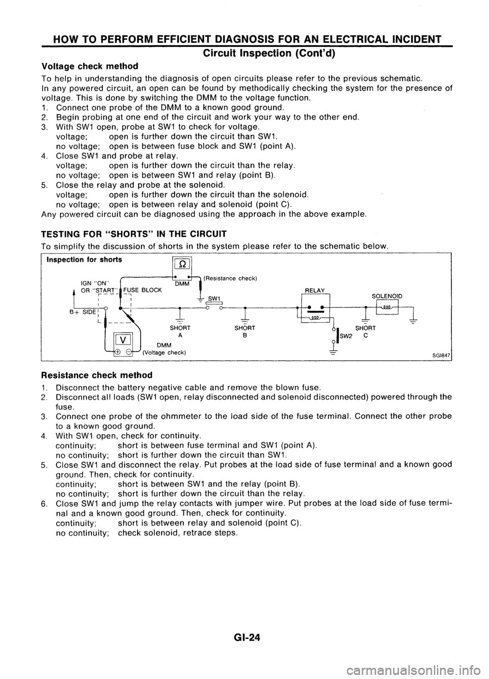
FOR"SHORTS" INTHE CIRCUIT
To simplify thediscussion ofshorts inthe system pleaserefertothe schematic below.
Inspection forshorts
Resistance checkmethod
1. Disconnect thebattery negative cableandremove theblown fuse.
2. Disconnect allloads (SW1open, relaydisconnected andsolenoid disconnected) poweredthroughthe
fuse.
3. Connect oneprobe ofthe ohmmeter tothe load sideofthe fuse terminal. Connecttheother probe
to aknown goodground.
4. With SW1open, check forcontinuity.
continuity; shortisbetween fuseterminal andSW1 (point A).
no continuity; shortisfurther downthecircuit thanSW1.
5. Close SW1anddisconnect therelay. Putprobes atthe load side offuse terminal andaknown good
ground. Then,check forcontinuity.
continuity; shortisbetween SW1andtherelay (point B),
no continuity; shortisfurther downthecircuit thantherelay.
6. Close SW1andjump therelay contacts withjumper wire.Putprobes atthe load sideoffuse termi-
nal and aknown goodground. Then,check forcontinuity.
continuity; shortisbetween relayandsolenoid (pointC).
no continuity; checksolenoid, retracesteps.
GI-24