1995 NISSAN ALMERA N15 steering wheel adjustment
[x] Cancel search: steering wheel adjustmentPage 711 of 1701
SERVICEDATAANDSPECIFICATIONS (50S)
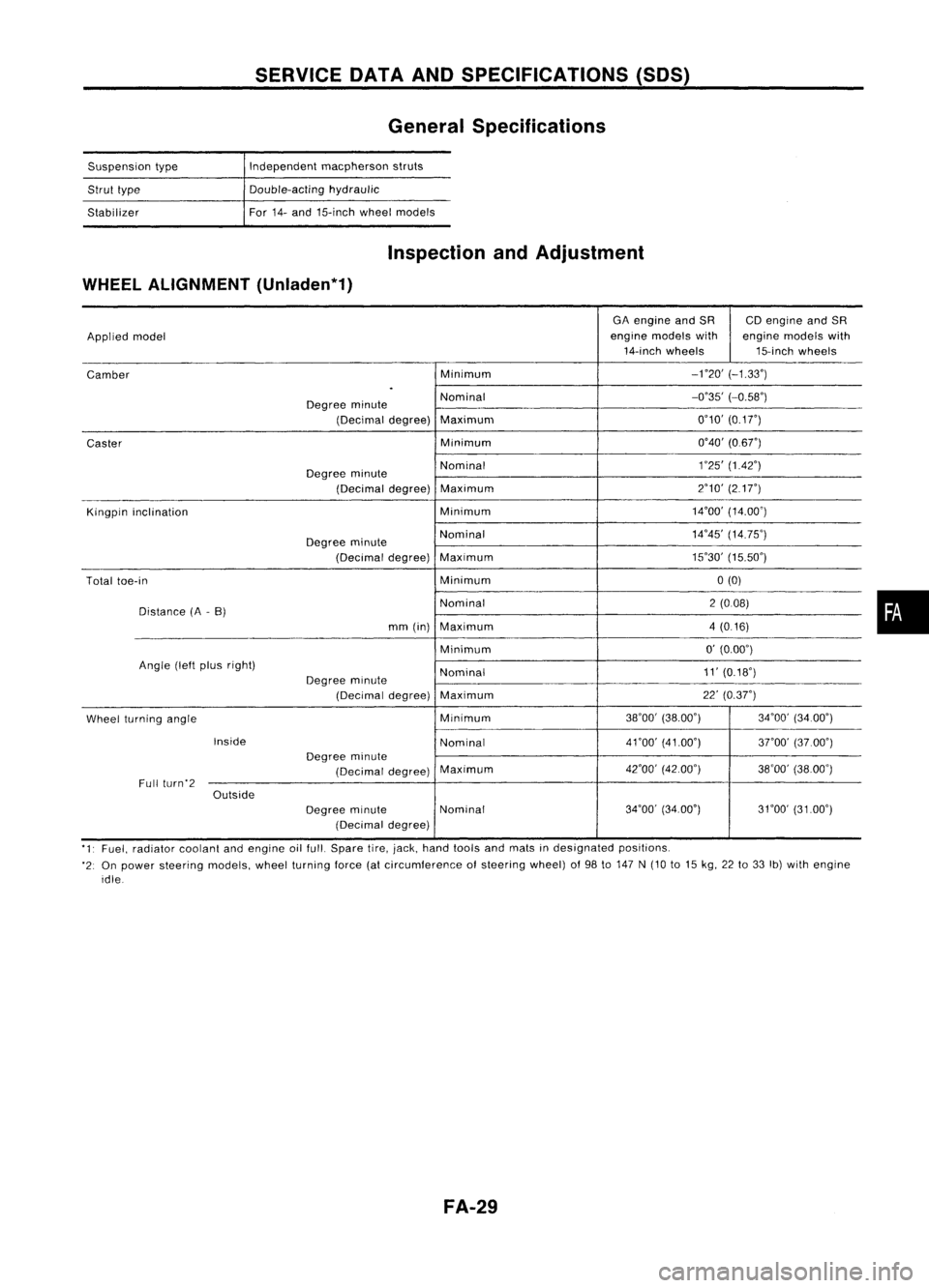
General Specifications
Suspension type
Strut type
Stabilizer Independent
macpherson struts
Double-acting hydraulic
For 14-and 15-inch wheelmodels
Inspection andAdjustment
WHEEL ALIGNMENT (Unladen*1)
GAengine andSR CDengine andSR
Applied model engine
models with enginemodels with
14-inch wheels 15-inchwheels
Camber Minimum
-no'
(-1.33')
.
Degree minute Nominal
-0'35'
(-0.58')
(Decimal degree)Maximum 0'10'
(0.1
r)
Caster Minimum
0'40'(0.6r)
Degree minute Nominal
1
'25' (1.42')
(Decimal degree)Maximum 2'10'
(217")
Kingpin inclination Minimum14'00'
(14.00')
Degree minute Nominal
14'45'
(14.75')
(Decimal degree)Maximum 15'30'
(15.50')
Total toe-in Minimum0(0)
Distance (A-B) Nominal
2(008)
mm (in) Maximum 4(0.16)
Minimum 0'
(0.00')
Angle (leftplus right)
Nominal 11'
(0.18')
Degree minute
(Decimal degree)Maximum 22'
(0.37")
Wheel turning angle Minimum
38'00'
(38.00') 34'00'(34.00')
Inside Nominal4nO'
(41.00')
3rOO'(37.00')
Degree minute
(Decimal degree)Maximum
42'00'
(42.00')
38'00'(38.00')
Full (urn'2
Outside
Degreeminute Nominal 34'00'
(34.00') 31'00'(3100')
(Decimal degree)
'1' Fuel, radiator coolantandengine oilfull. Spare tire,jack, hand tools andmats indesignated positions.
'2: On power steering models,wheelturning force(atcircumference ofsteering wheel)of98 to147 N(10 to15 kg, 22to33 Ib)with engine
idle
FA-29
•
Page 774 of 1701
ON-BOARDDIAGNOSTIC SYSTEMDESCRIPTION
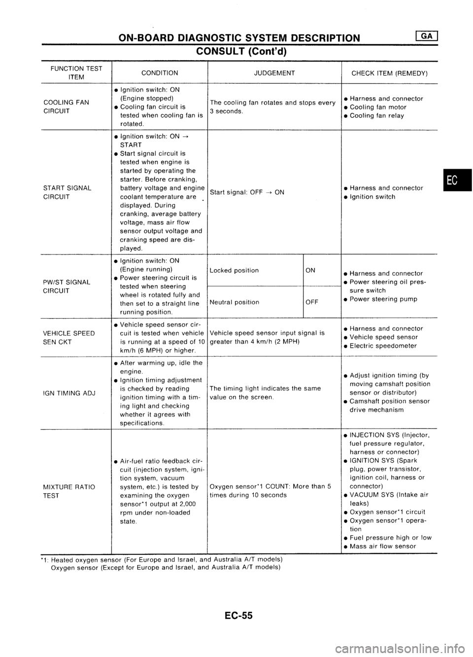
CONSULT (Conl'd)
FUNCTION TEST
CONDITION JUDGEMENT
ITEM CHECK
ITEM(REMEDY)
• Ignition switch:ON
COOLING FAN (Engine
stopped)
Thecooling fanrotates andstops every •
Harness andconnector
CIRCUIT •
Cooling fancircuit is
3seconds. •
Cooling fanmotor
tested whencooling fanis
•Cooling fanrelay
rotated .
• Ignition switch:ON-.
START
• Start signal circuit is
tested whenengine is
started byoperating the
starter. Beforecranking,
START SIGNAL batteryvoltage andengine
Startsignal: OFF-.ON •
Harness andconnector
CIRCUIT coolanttemperature are •
Ignition switch
displayed. During
cranking, averagebattery
voltage, massairflow
sensor outputvoltage and
cranking speedaredis-
played .
• Ignition switch:ON
(Engine running)
Lockedposition ON
•Harness andconnector
PW/ST SIGNAL •
Power steering circuitis
•Power steering oilpres-
tested whensteering
CIRCUIT wheelisrotated fullyand sure
switch
then settoastraight lineNeutral
position OFF•
Power steering pump
running position.
• Vehicle speedsensor cir-
•Harness andconnector
VEHICLE SPEED cuit
istested whenvehicle Vehicle
speedsensor inputsignal is
•Vehicle speedsensor
SEN CKT is
running ataspeed of10 greater
than4km/h (2MPH)
•Electric speedometer
km/h (6MPH) orhigher .
• After warming up,idle the
engine. •Adjust ignition timing(by
• Ignition timingadjustment
movingcamshaft position
IGN TIMING ADJ is
checked byreading The
timing lightindicates thesame
sensorordistributor)
ignition timingwithatim- value
onthe screen.
•Camshaft positionsensor
ing light andchecking
drivemechanism
whether itagrees with
specifications.
•INJECTION SYS(Injector,
fuel pressure regulator,
harness orconnector)
• Air-fuel ratiofeedback cir- •
IGNITION SYS(Spark
cuit (injection system,igni- plug,
power transistor,
tion system, vacuum ignition
coil,harness or
MIXTURE RATIO system,
etc.)istested byOxygen
sensor'1 COUNT:Morethan5 connector)
TEST examining
theoxygen times
during 10seconds •
VACUUM SYS(Intake air
sensor'1 outputat2,000 leaks)
rpm under non-loaded •
Oxygen sensor'1 circuit
state. •
Oxygen sensor'1 opera-
tion
• Fuel pressure highorlow
• Mass airflow sensor
'1: Heated oxygen sensor(ForEurope andIsrael, andAustralia AITmodels)
Oxygen sensor(Except forEurope andIsrael, andAustralia
A/T
models)
EC-55
•
Page 980 of 1701
ON-BOARDDIAGNOSTIC SYSTEMDESCRIPTION
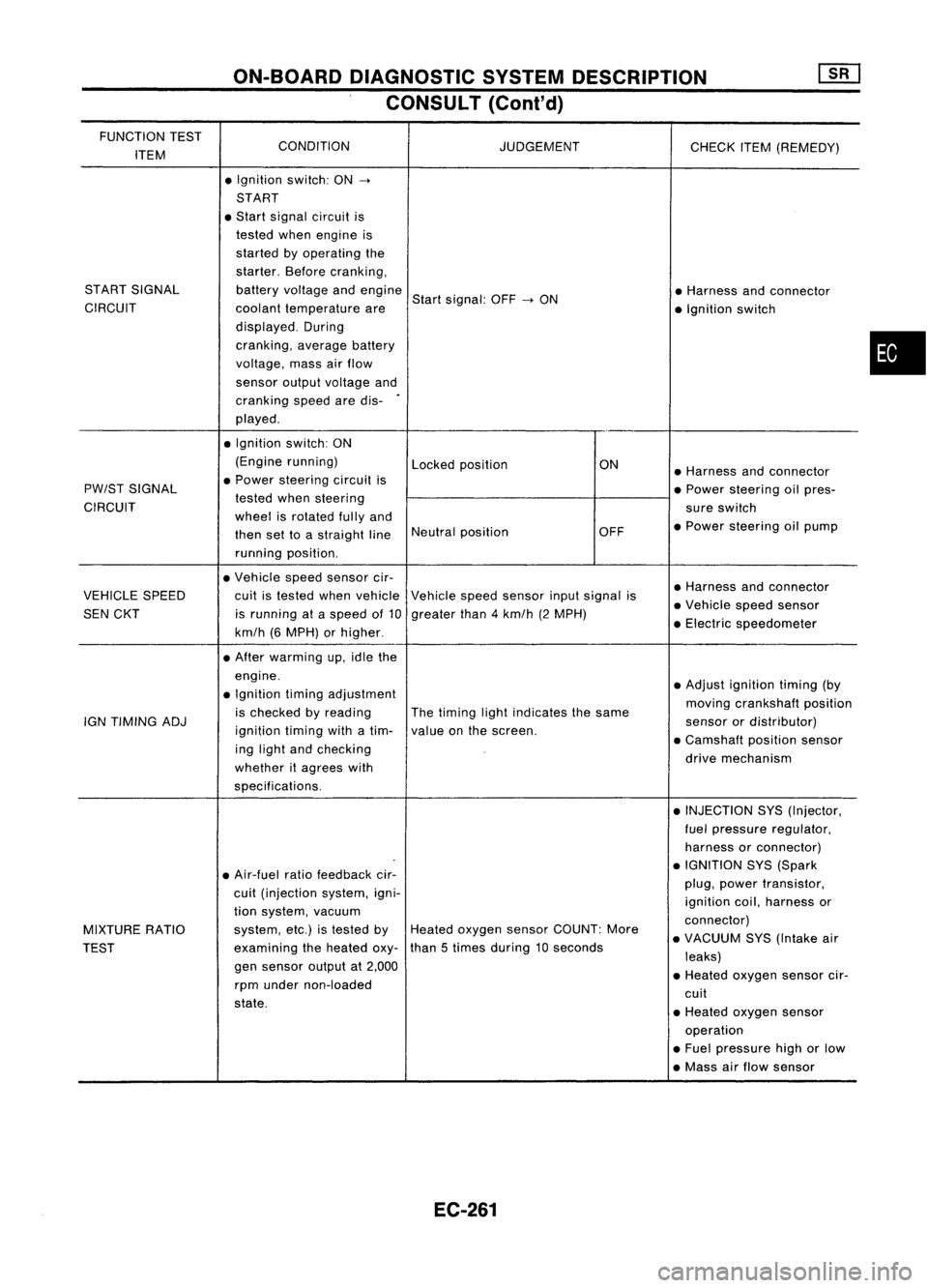
CONSULT (Cont'd)
FUNCTION TEST
CONDITION
ITEM JUDGEMENT
CHECKITEM(REMEDY)
• Ignition switch:ON
->
START
• Start signal circuit is
tested whenengine is
started byoperating the
starter. Beforecranking,
START SIGNAL batteryvoltage andengine
Startsignal: OFF
->
ON •
Harness andconnector
CIRCUIT coolanttemperature are
•Ignition switch
displayed. During
cranking, averagebattery
voltage, massairflow
sensor outputvoltage and
cranking speedaredis-
.
played .
• Ignition switch:ON
(Engine running)
Lockedposition ON
•Harness andconnector
PW/ST SIGNAL •
Power steering circuitis
•Power steering oilpres-
CIRCUIT tested
whensteering
sureswitch
wheel isrotated fullyand
•Power steering oilpump
then settoastraight lineNeutral
position OFF
running position.
• Vehicle speedsensor cir-
•Harness andconnector
VEHICLE SPEED cuitistested whenvehicle Vehiclespeedsensor inputsignal is
•Vehicle speedsensor
SEN CKT isrunning ataspeed of10 greater than4km/h (2MPH)
•Electric speedometer
km/h (6MPH) orhigher .
• After warming up,idle the
engine. •Adjust ignition timing(by
• Ignition timingadjustment
movingcrankshaft position
is checked byreading Thetiming lightindicates thesame
IGN TIMING ADJ
ignitiontimingwithatim- valueonthe screen. sensor
ordistributor)
ing light andchecking •
Camshaft positionsensor
whether itagrees with drive
mechanism
specifications. •INJECTION SYS(Injector,
fuel pressure regulator,
harness orconnector)
• Air-fuel ratiofeedback cir- •
IGNITION SYS(Spark
cuit (injection system,igni- plug,
power transistor,
ignition coil,harness or
tion system, vacuum
connector)
MIXTURE RATIO system,
etc.)istested byHeated oxygen sensorCOUNT: More
•VACUUM SYS(Intake air
TEST examining
theheated oxy-than
5times during 10seconds
leaks)
gen sensor outputat2,000
•Heated oxygen sensorcir-
rpm under non-loaded
cuit
state. •Heated oxygen sensor
operation
• Fuel pressure highorlow
• Mass airflow sensor
EC-261
•
Page 1667 of 1701
STEERINGSYSTEM
SECTIONST
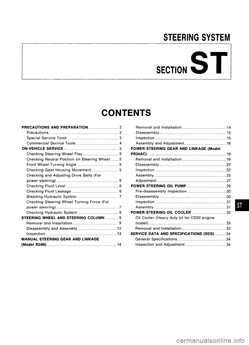
CONTENTS
PRECAUTIONS ANDPREPARATION 2
Precautions 2
Special Service Tools 3
Commercial ServiceTools 4
ON-VEHICLE SERVICE
5
Checking SteeringWheelPlay 5
Checking NeutralPosition onSteering Wheel 5
Front Wheel Turning Angle 5
Checking GearHousing Movement 5
Checking andAdjusting DriveBelts(For
power steering) 6
Checking FluidLevel 6
Checking FluidLeakage 6
Bleeding Hydraulic System 7
Checking SteeringWheelTurning Force(For
power steering) 7
Checking Hydraulic System 8
STEERING WHEElANDSTEERING COLUMN 9
Removal andInstallation 9
Disassembly andAssembly 12
Inspection 13
MANUAL STEERING GEARANDLINKAGE
(Model R24N) 14
Removal
andInstallation 14
Disassembly 15
Inspection 15
Assembly andAdjustment... 16
POWER STEERING GEARANDLINKAGE (Model
PR24AC) 19
Removal andInstallation 19
Disassembly 22
Inspection 22
Assembly ,.. 23
Adjustment 27
POWER STEERING OILPUMP 29
Pre-disassembly Inspection 30
Disassembly 30
Inspection 31
Assembly 31
POWER STEERING OILCOOLER
33
Oil Cooler (Heavy dutykitfor CD20 engine
model) 33
Removal andInstallation 33
SERVICE DATAANDSPECIFICATIONS
(505)34
General Specifications 34
Inspection andAdjustment 34
•
Page 1700 of 1701
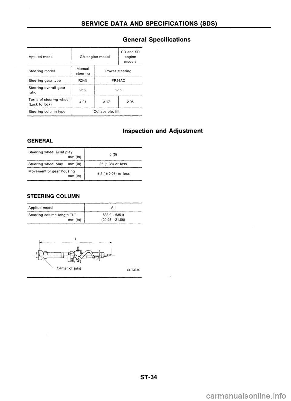
SERVICEDATAANDSPECIFICATIONS (SOS)
General Specifications
CD and SR
Applied model GAengine model engine
models
Steering model Manual
Powersteering
steering
Steering geartype R24N PR24AC
Steering overallgear
23.2 17.1
ratio
Turns ofsteering wheel
4.21 3.172.95
(Lock tolock)
Steering columntype Collapsible,tilt
Inspection andAdjustment
GENERAL
Steering wheelaxialplay
mm (in)
Steering wheelplay mm(in)
Movement ofgear housing
mm (in)
STEERING COLUMN
Applied model
Steering columnlength"L"
mm (in)
L
'"
'- Center ofjoint 0(0)
35 (1.38) orless
:!:
2 (
:!:
0.08) orless
All
533.0 -535.0
(20.98 -21.06)
SST334C
ST-34
Page 1701 of 1701
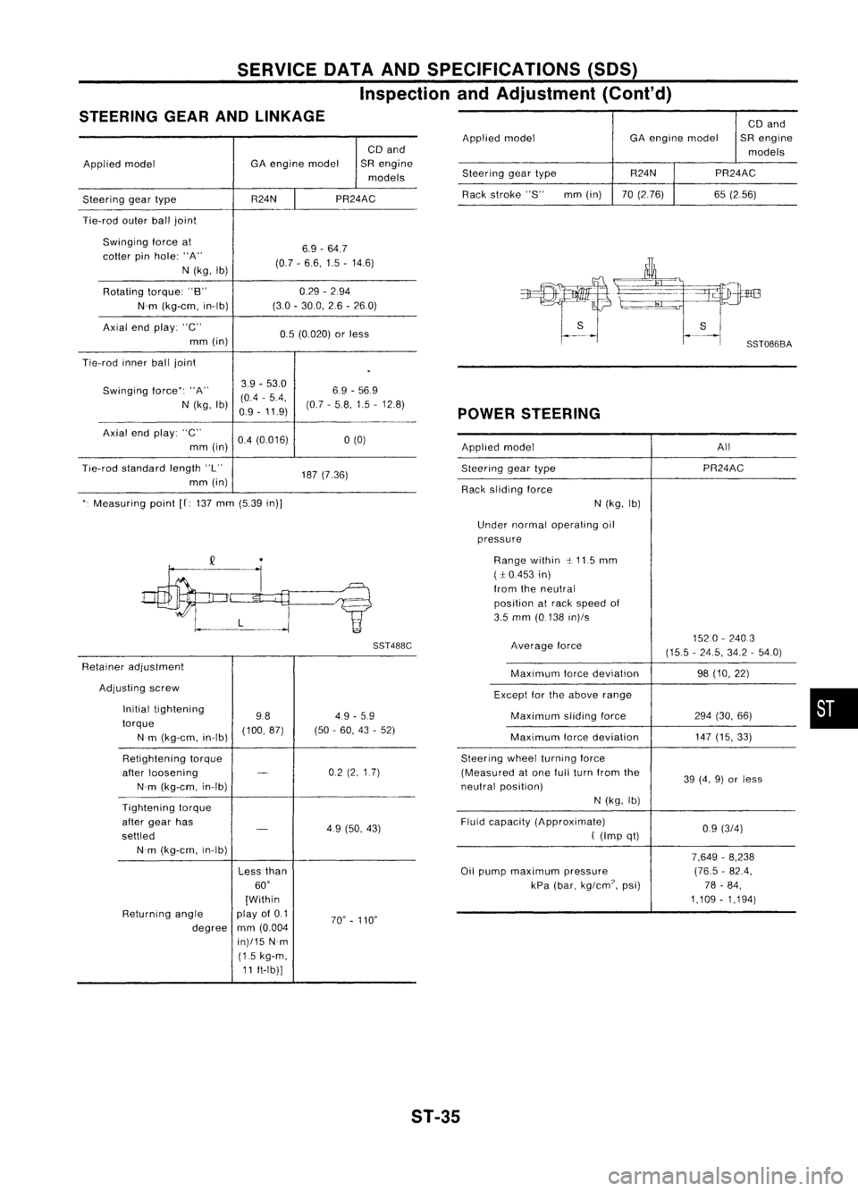
SERVICEDATAANDSPECIFICATIONS (50S)
Inspection andAdjustment (Cont'd)
STEERING GEARANDLINKAGE
CDand
Applied model GA
engine model SRengine
models
Steering geartype R24NPR24AC
Tie-rod outerballjoint
Swinging forceat
6.9-64.7
cotter pinhole: "A"
(0.7-6.6, 1.5-14.6)
N (kg, Ib)
Rotating torque:"B" 0.29
-294
N'm (kg-em, in-Ib) (30
-30.0, 26-260)
Axial endplay: "C"
0.5(0.020) orless
mm (in)
Tie-rod innerballjoint
.
Swinging force":"A" 3.9
-53.0
6.9-569
(0.4 -5.4,
N (kg, Ib)
0.9-11.9) (07
-58,1.5 -12.8)
Axial endplay: "C"
0.4(0.016)
a
(0)
mm (in)
Tie-rod standard length"L"
187(7.36)
mm (in)
". Measuring point
[f:
137 mm (5.39 in)]
SST488C
Retainer adjustment
Adjusting screw
Initial tightening
984.9
-5.9
torque (100,87)(50-60, 43-52)
Nm (kg-em, in-Ib)
Retightening torque
after loosening
-
02
(2,1.7)
N'm (kg-em, in-Ib)
Tightening torque
after gear has
-
49(50, 43)
settled
N'm (kg-em, in-Ib)
Lessthan
60'
[Within
Returning angle play
of0.1
70'-110'
degree mm
(0.004
in)/15 N'm
(1.5 kg-m,
11 ft-Ib)] CD
and
Applied model GAengine model SRengine
models
Steering geartype R24N
PR24AC
Rack stroke "S" mm(in) 70(2.76) 65(2.56)
POWER STEERING
Applied model All
Steering geartype PR24AC
Rack sliding force
N(kg, Ib)
Under normal operating oil
pressure
Range within ~.115 mm
(:1:0.453 in)
from theneutral
position atrack speed of
3.5 mm (0.138 in)/s
Average force 1520
-2403
(15.5 -24.5, 34.2-54.0)
Maximum forcedeviation 98(10, 22)
Except forthe above range
Maximum slidingforce 294(30, 66)
Maximum forcedeviation 147
(15, 33)
Steering wheelturning force
(Measured atone fullturn from the
39(4, 9)or less
neutral position)
N(kg, Ib)
Fluid capacity (Approximate)
0.9(3/4)
f
(Imp qt)
7,649-8,238
Oil pump maximum pressure (76.5
-82.4,
kPa (bar, kg/em?, psi) 78-84,
1,109 -1,194)
•
ST-35