Page 17 of 1701

AIT FLUID CHECK
Fluid leakage check
1. Clean areasuspected ofleaking, -for example, mating
surface ofconverter housingandtransmis")
Fluidleakage TROUBLE
DIAGNOSES
Preliminary Check(PriortoRoad Testing)
AIT FLUID CHECK
Fluid leakage check
1. Clean areasuspected ofleaking, -for example, mating
surface ofconverter housingandtransmission case.
2. Start engine, applyfootbrake, placeselector leverin"0"
position andwait afew minutes.
3. Stop engine.
4. Check forfresh leakage.
SAT288G
Fluidcondition check
Fluid levelcheck -Refer toMA section (CHASSIS AND
BODY MAINTENANCE).
Fluid
color
Oark orblack withburned odor
Milky pink
Varnished fluid,lighttodark brown
and tacky Suspected
problem
Wear offrictional material
Water contamination
- Road water entering through
filler tubeorbreather
Oxidation
- Over orunder filling
- Overheating
•
Road Testing
Perform roadtests using "Symptom" chart.Refertopage
AT-20.
"P"
POSITION
1. Place selector leverin"P" position andstart engine. Stop
engine andrepeat theprocedure inall positions, including
neutral position.
2. Stop vehicle onaslight upgrade andplace selector leverin
"P" position. Releaseparkingbraketomake surevehicle
remains locked.
"R"
POSITION
1. Manually moveselector leverfrom"P"to"R", andnote
shift quality.
2. Drive vehicle inreverse longenough todetect slippage or
other abnormalities.
"N"
POSITION
1. Manually moveselector leverfrom"R"and"0"to"N" and
note shift quality.
2. Release parkingbrakewithselector leverin"N" position.
Lightly depress accelerator pedaltomake surevehicle
does notmove. (When vehicle isnew orsoon afterclutches
have been replaced, vehiclemaymove slightly. Thisisnot
a problem.)
AT-17
Page 52 of 1701
Model
34X68
SAT496HB
SAT0170
DISASSEMBL
Y
b. Remove stopperringfrom terminal body.
c. Push terminal bodyintotransmission caseanddraw out
solenoid harness.
10. Remove manualvalvefromcontrol valveassembly.
11. Remove returnspring fromSIRaccumulator piston.
12. Remove SIRaccumulator pistonwithcompressed air.
13. Remove O-ringsfromSIRaccumulator piston.
AT-52
Page 61 of 1701
Parkingshaft
SAT064D
SAT702D DISASSEMBL
V
44. Remove forwardclutchassembly fromtransmission case.
45. Remove thrustwasher andbearing racefrom transmission
case.
- All models - •
46. Remove returnspring fromparking shaftusing ascrew-
i
driver.
- Except model34X81-
47. Remove outputshaft,output gearandreduction piniongear
according tothe following procedures.
a. Remove sidecover.
• Donot reuse sidecover bolts.
b. Set manual leverto"p" position tofix idler gear andout-
put gear.
c. Unlock bothidlergear andoutput gearlocknuts using apin
punch.
AT-61
Page 66 of 1701
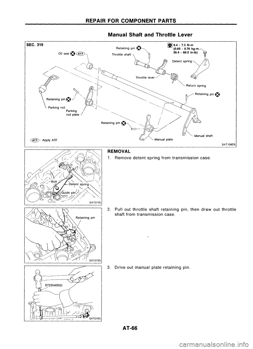
SEC.319
c&D:
ApplyATF. REPAIR
FORCOMPONENT PARTS
Manual ShaftandThrottle Lever
~ 6.4•7.5 N.m
Retaining pm~~ (0.65-0.76 kg-m. "-
Throttle shaft ~ 56.4-66.0 In-Ib)
f
~ 0.""
''''0'''11)
Th""'. ,,~,/ ,
V
~ Return spnng
~ Retaining pin~
)
SAT109EB
REMOVAL
1. Remove detentspringfromtransmission case.
2. Pullout throttleshaftretaining pin,then draw outthrottle
shaft fromtransmission case.
3. Drive outmanual plateretaining pin.
AT-66
Page 67 of 1701
REPAIRFORCOMPONENT PARTS
Manual ShaftandThrottle Lever(ConI'd)
4. Drive andthen pulloutparking rodplate retaining pin.
5. Remove parkingrodplate frommanual shaft.
6. Draw outparking rodfrom transmission case.
7. Pull outmanual shaftretaining pin. •
8. Remove manualshaftandmanual platefromtransmission
i
case.
9. Remove manualshaftoilseal.
SATOBOD
INSPECTION
• Check component partsforwear ordamage. Replaceif
necessary.
AT-67
Page 68 of 1701
REPAIRFORCOMPONENT PARTS
Manual ShaftandThrottle Lever(Cont'd)
INSlALLA liON
1. Install manual shaftoilseal.
• Apply ATFtoouter surface ofoil seal.
2. Install throttle leverandreturn spring onthrottle shaft.
3. Install throttle leverassembly ontransmission case.
4. Align groove ofthrottle shaftandhole oftransmission case.
5. Install throttle shaftretaining pin.
6. Move throttle leverinthe direction ofthe arrow.
7. Install manual shaftandmanual plate.
8. Align groove ofmanual shaftandhole oftransmission case.
9. Install manual shaftretaining pin.
AT-68
Page 161 of 1701
\~~~~~C0\
~~ \.---.!
~ />"0
o
<=~~ )'()
Throttle lever'~ ~\
~ Il';-,~\ ,~\\)
,./, Manual plate
2\ (
. ~ -P-' (\
d (
Detent valve
/- \, 'sdJ :----, \,,,
n\ ';\ ~ "~
Manualvalve
\3l~w1:
nd\'~~\ \\)~
\(--' "'!f ()~
r:,
A~
\ ~ SAT414D
SAT664D ASSEMBLY
Assembly 4(Conl'd)
b, Set manual shaftinNeutral position.
c. Install control valveassembly ontransmission casewhile
aligning manualvalvewithmanual plateanddetent valve
with throttle lever.
d. Pass solenoid harnessthroughtransmission caseand
install terminal bodyontransmission casebypushing
it.
e. Install cliptoterminal body.
f.
Tighten bolts@,
@. ~
and
@.
Bolt length, number andlocation:
Bolt
@
@ @
@
Bolt length
'T'
mm
(in)
33,0
40,0
43,525,0
(1.299) (1.575)(1,713)
(0.984)
Number ofbolts
652
2
Tightening torque
7-9 (0,7 -0.9, 61-78)
N'm (kg-m, in-Ib)
12. Install oilpan.
a. Attach magnet tooil pan.
AT-161
•
Page 163 of 1701
SAT620E
SAT586H
SAT428DA
Torque
converter
ASSEMBLY
Assembly 4(Cont'd)
14. Install inhibitor switch.
a. Set manual shaftin"P" position.
b. Temporarily installinhibitor switchonmanual shaft.
c.
Move
selector
lever
to"N" position.
d. Use a4mm (0.157 in)pin forthis adjustment.
1) Insert thepinstraight intothemanual shaftadjustment hole.
2) Rotate inhibitor switchuntilthepincan also beinserted
straight intohole ininhibitor switch.
e. Tighten inhibitor switchfixingbolts.
f. Remove pinfrom adjustment holeafter adjusting inhibitor
switch.
15. Install oilcharging pipeandoilcooler tubetotransmission •
case.
16. Install torque converter.
a. Pour ATFintotorque converter.
• Approximately 1liter (7/8Impqt)offluid isrequired fora
new torque converter.
• When reusing oldtorque converter, addthesame amount
of fluid aswas drained.
b. Install torque converter whilealigning notchesoftorque
converter withnotches ofoil pump.
AT-163


4. Drive andthen pulloutparking rodplate retaining pin.
5. Remove parkingrodplate frommanual shaft.
6. Draw outparking rodfrom trans")

INSlALLA liON
1. Install manual shaftoilseal.
• Apply ATFtoouter surface ofoil seal.
2. Install throttle leverandreturn spring")
'()
Throttle lever'~ ~\
~ Il';-,~\ ,~\\)
,./, Manual plate
2\ (
. ~ -P-' (\
d (
Detent valve
/- \, 'sdJ :----, \,,,
n\ ';\ ~ &")

14. Install inhibitor switch.
a. Set manual shaftin\"P\" position.
b. Temporarily installinhibitor switchonmanual sha")