1995 NISSAN ALMERA N15 Check light
[x] Cancel search: Check lightPage 17 of 1701

Fluidleakage TROUBLE
DIAGNOSES
Preliminary Check(PriortoRoad Testing)
AIT FLUID CHECK
Fluid leakage check
1. Clean areasuspected ofleaking, -for example, mating
surface ofconverter housingandtransmission case.
2. Start engine, applyfootbrake, placeselector leverin"0"
position andwait afew minutes.
3. Stop engine.
4. Check forfresh leakage.
SAT288G
Fluidcondition check
Fluid levelcheck -Refer toMA section (CHASSIS AND
BODY MAINTENANCE).
Fluid
color
Oark orblack withburned odor
Milky pink
Varnished fluid,lighttodark brown
and tacky Suspected
problem
Wear offrictional material
Water contamination
- Road water entering through
filler tubeorbreather
Oxidation
- Over orunder filling
- Overheating
•
Road Testing
Perform roadtests using "Symptom" chart.Refertopage
AT-20.
"P"
POSITION
1. Place selector leverin"P" position andstart engine. Stop
engine andrepeat theprocedure inall positions, including
neutral position.
2. Stop vehicle onaslight upgrade andplace selector leverin
"P" position. Releaseparkingbraketomake surevehicle
remains locked.
"R"
POSITION
1. Manually moveselector leverfrom"P"to"R", andnote
shift quality.
2. Drive vehicle inreverse longenough todetect slippage or
other abnormalities.
"N"
POSITION
1. Manually moveselector leverfrom"R"and"0"to"N" and
note shift quality.
2. Release parkingbrakewithselector leverin"N" position.
Lightly depress accelerator pedaltomake surevehicle
does notmove. (When vehicle isnew orsoon afterclutches
have been replaced, vehiclemaymove slightly. Thisisnot
a problem.)
AT-17
Page 18 of 1701

SAT497GTROUBLE
DIAGNOSES
Road Testing (Cont'd)
"0"
POSITION
1. Manually moveselector leverfrom"N"to"D" position, and
note shiftquality.
2. Using theshift schedule asareference, drivevehicle in"D"
position. Record,onsymptom chart,respective vehicle
speeds atwhich up-shifting anddown-shifting occur.These
speeds aretobe read atthree different throttlepositions
(light, halfandfull), respectively. Alsodetermine thetiming
at which shocks areencountered duringshifting andwhich
clutches areengaged.
SAT612GA
3.Determine whetherlock-upproperly occurswhiledriving
vehicle inproper gearposition andatproper vehicle speed.
4. Check todetermine ifshifting tooverdrive gearcannot be
made whileODcontrol switchis"OFF".
5. Drive vehicle in"D
3"
position athalf tolight throttle posi-
tion. Keep driving at60 to70 km/h (34to43 MPH). FUlly
depress accelerator pedaltomake suretransaxle down-
shifts from3rdto2nd gear.
6. Drive vehicle in"D
2"
position athalf tolight throttle posi-
tion. Keep driving at25 to35 km/h (16to22 MPH). Fully
depress accelerator pedaltomake suretransaxle down-
shifts from2ndto1st gear.
"2"
POSITION
1. Shift to"2" position andmake surevehicle startsin1st
gear.
2. Increase vehiclespeedtomake suretransaxle upshiftsfrom
1st to2nd gear.
3. Further increase vehiclespeed.Makesuretransaxle does
not upshift to3rd gear.
4. Drive vehicle in"2
2"
position athalf tolight throttle position.
Keep driving at25 to35 km/h (16to22 MPH). Fullydepress
accelerator pedaltomake suretransaxle downshifts from
2nd to1st gear.
5. Allow vehicle torun idle while in"2" position tomake sure
that transaxle downshifts to1st gear.
6. Move selector leverto"D" position andallow vehicle to
operate at30 to40 km/h (19to25 MPH). Then,shiftto"2"
position tomake suretransaxle downshifts to2nd gear.
"1"
POSITION
1. Place selector leverin"1" position andaccelerate vehicle.
Make suretransaxle doesnotshift from 1stto2nd gear
although vehiclespeedincreases.
2. Drive vehicle in"1" position. Releaseaccelerator pedalto
make surethatengine compression actsasabrake.
3. Place selector leverin"D" or"2" position andallow vehi-
cle torun at15 to25 km/h (9to 16 MPH). Thenmove selec-
tor lever to"1" position tomake suretransaxle downshifts
to 1st gear.
AT-18
Page 41 of 1701

Boltlength
'T'
mm (in)
55 (2.17)
50 (1.97)
65 (2.56)
25 (0.98)
40 (1.57)
Tightening
torque
N'm (kg-m, ft-Ib)
70 -79 (7.1 -8.1,51 -59)
70 -79 (7.1 -8.1, 51-59)
70 -79 (7.1 -8.1,51 -59)
30 -40 (3.1 -4.1, 22-30)
30 -40 (3.1 -4.1, 22-30)
CD
@
@
@
@
Bolt
No.
• Reinstall anypart removed.
• Adjust throttle wireandcontrol cable.Referto"ON-VEHI-
CLE SERVICE", AT-33,35.
•. Check inhibitor switch.Referto"Electrical Components
Inspection", AT-3D.
• Refill transaxle withATFandcheck fluidlevel, AT-17.
• Move selector leverthrough allpositions tobe sure that
transaxle operatescorrectly. Withparking brakeapplied,
idle engine. Moreselector leverthrough "N"to"D", to"2",
to "1" and "R". Aslight shock should befelt through the
hand gripping theselector eachtimethetransaxle is
shifted. •
• Perform roadtest-Refer to"ROAD TESTING", AT-17.
i
REMOVAL
ANDINSTAllATION
Installation (Cont'd)
SR engine models
SAT638A
SAT558DA
AIT
toengine
@
Engine to
AIT
AT-41
Page 87 of 1701

REPAIRFORCOMPONENT PARTS
Control ValveUpper Body(Cont'd)
DISASSEMBL Y
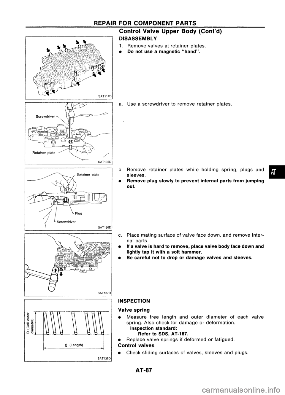
1. Remove valvesatretainer plates.
• Donot use amagnetic "hand".
SAT114D
a.Use ascrewdriver toremove retainer plates.
SAT135D
b.Remove retainerplateswhileholding spring,plugsand•
sleeves.
• Remove plugslowly toprevent internalpartsfromjumping
out.
c. Place mating surface ofvalve facedown, andremove inter-
nal parts.
• If
avalve ishard toremove, placevalvebodyfacedown and
lightly tapitwith asoft hammer.
• Becareful nottodrop ordamage valvesandsleeves.
SAT137D INSPECTION
Q
(Length) Valve
spring
• Measure freelength andouter diameter ofeach valve
spring. Alsocheck fordamage ordeformation.
Inspection standard:
Refer to50S, AT-167.
• Replace valvesprings ifdeformed orfatigued.
Control valves
• Check sliding surfaces ofvalves, sleeves andplugs.
SAT138D
AT-87
Page 285 of 1701

OKNGBRAKE
BOOSTER
On-vehicle Service
OPERATING CHECK
• Depress brakepedalseveral timeswithengine off.After
exhausting vacuum,makesurethere isno change inpedal
stroke.
• Depress brakepedal, thenstart engine. Ifpedal goesdown
slightly, operation isnormal.
AIRTIGHT CHECK
• Start engine, andstop itafter oneortwo minutes. Depress
SBR002A
brakepedalseveral timesslowly. Booster isairtight ifpedal
stroke isless each time.
• Depress brakepedalwhileengine isrunning, andstop
engine withpedal depressed. Thepedal stroke should not
change afterholding pedaldownfor
30seconds.
SBR365AA Removal
CAUTION:
• Becareful nottosplash brakefluidonpainted areas;itmay
cause paintdamage. Ifbrake fluidissplashed onpainted
areas, washitaway withwater immediately.
• Be careful nottodeform orbend brake pipes, during
removal ofbooster.
SEC.
465.470
BR-15Gasket
~ :N.m (kg-m. ft-Ib)
SBR223BB
•
Page 286 of 1701

Approx.125mm (4.92 In) BRAKE
BOOSTER
Inspection
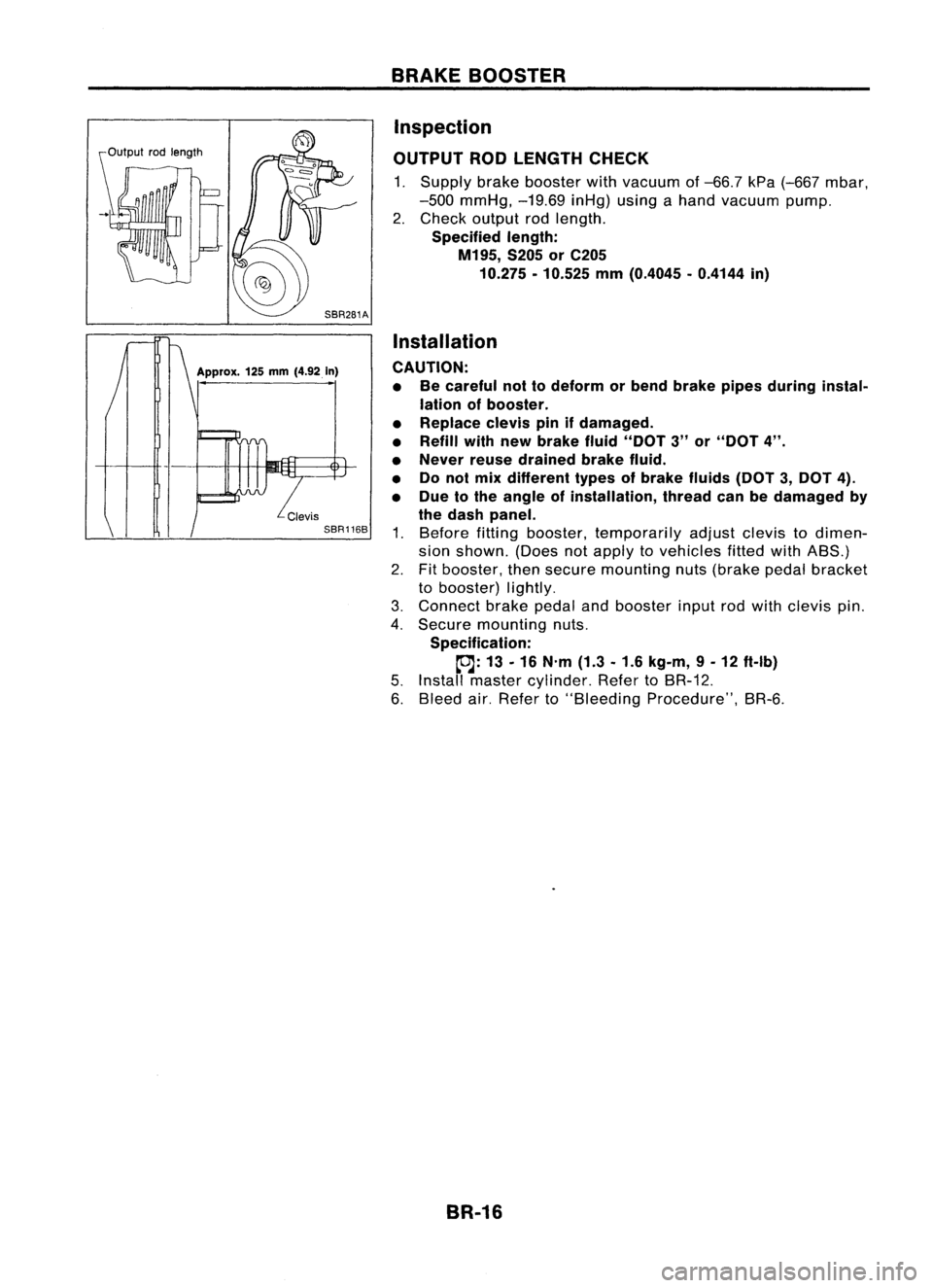
OUTPUT RODLENGTH CHECK
1. Supply brakebooster withvacuum of-66.7 kPa(-667 mbar,
-500 mmHg, -19.69inHg)usingahand vacuum pump.
2. Check output rodlength.
Specified length:
M195, S205orC205
10.275 -10.525 mm(0.4045 -0.4144 in)
Installation
CAUTION: • Becareful nottodeform orbend brake pipesduring instal-
lation ofbooster.
• Replace clevispinifdamaged.
• Refill withnewbrake fluid"DOT 3"or"DOT 4".
• Never reusedrained brakefluid.
• Donol mix different typesofbrake fluids(DOT3,DOT 4).
• Due tothe angle ofinstallation, threadcanbedamaged by
the dash panel.
1. Before fittingbooster, temporarily adjustclevistodimen-
sion shown. (Doesnotapply tovehicles fittedwithABS.)
2. Fitbooster, thensecure mounting nuts(brake pedalbracket
to booster) lightly.
3. Connect brakepedalandbooster inputrodwith clevis pin.
4. Secure mounting nuts.
Specification:
~: 13-16 N'm (1.3-1.6 kg-m, 9-12 ft-Ib)
5. Install master cylinder. RefertoBR-12.
6. Bleed air.Refer to"Bleeding Procedure", BR-6.
BR-16
Page 308 of 1701

ANTI-LOCKBRAKESYSTEM
Purpose
The Anti-Lock BrakeSystem (ABS)consists ofelectronic andhydraulic components. Itallows forcon-
trol ofbraking forcesothat locking ofthe wheels canbeavoided.
The ABS:
1) Improves propertracking performance throughsteering wheeloperation.
2) Eases obstacles tobe avoided throughsteering wheeloperation.
3) Improves vehiclestability bypreventing flatspins.
Operation
• When thevehicle speedisless than 10km/h (6MPH) thissystem doesnotwork.
• The Anti-Lock BrakeSystem (ABS)hasself-test capabilities. Thesystem turnsonthe ABS warning
light for1second afterturning theignition switchON.The system performs anothertestthefirst time
the vehicle reaches 6km/h (4MPH). Amechanical noisemaybeheard asthe ABS performs aself-
test. This isanormal partofthe self-test feature.Ifa malfunction isfound during thischeck, theABS
warning lightwillcome on.
• During ABSoperation, amechanical noisemaybeheard. Thisisanormal condition.
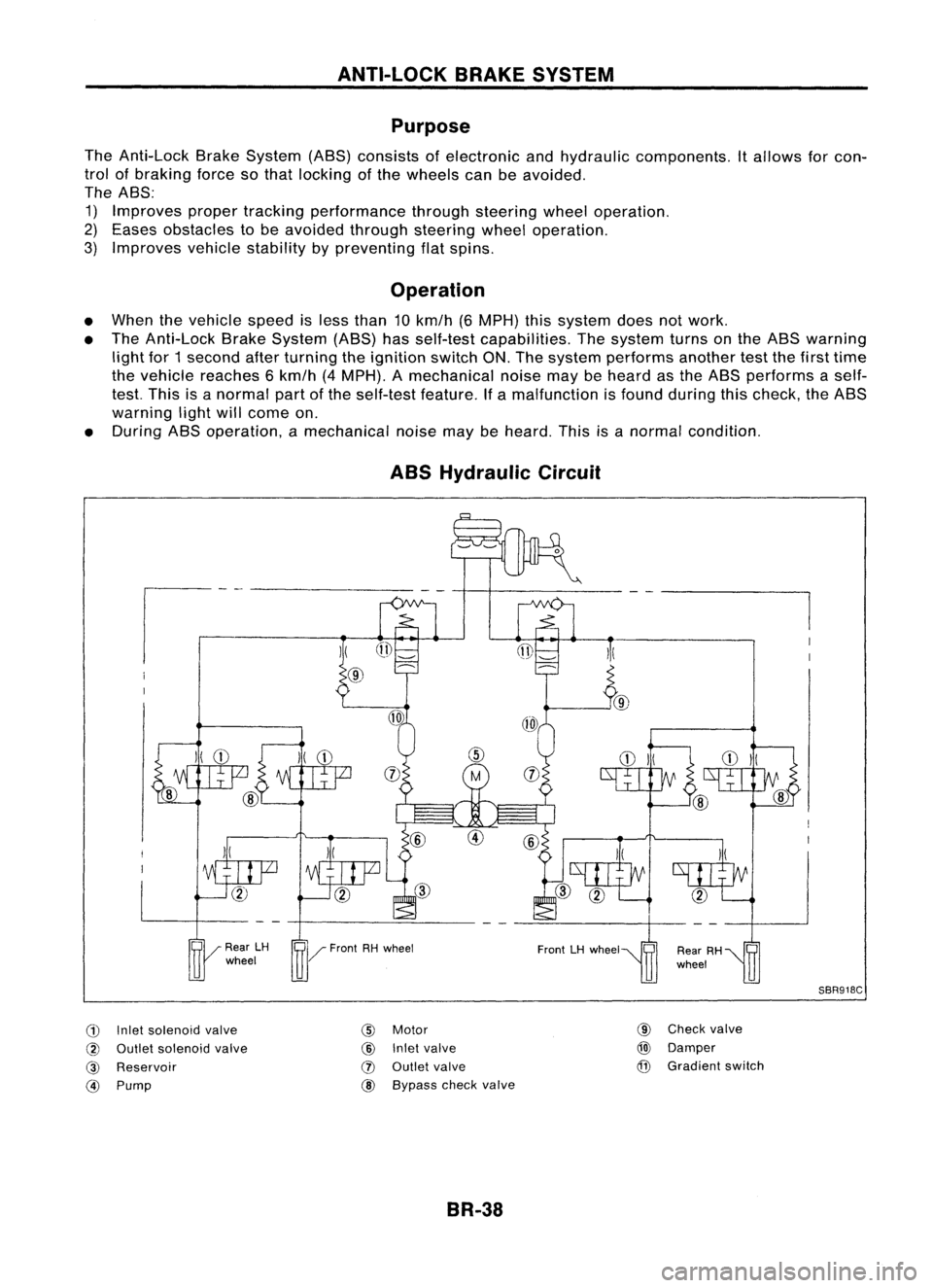
ABS Hydraulic Circuit
G)
Inletsolenoid valve
@
Outlet solenoid valve
@
Reservoir
@)
Pump
)(
@
@
Motor
@
Inletvalve
(J)
Outlet valve
@ Bypass checkvalve
BR-38 @
Check valve
@)
Damper
@
Gradient switch
SBR918C
Page 338 of 1701

TROUBLEDIAGNOSES
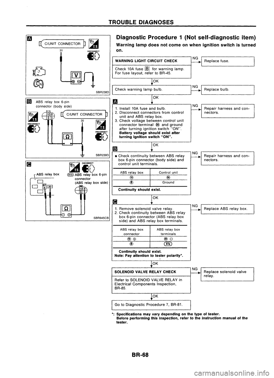
Diagnostic Procedure1(Not self-diagnostic item)
Warning lampdoes notcome onwhen ignition switchisturned
on.
c(
C/UNIT CONNECTOR
30
p~
15
SBR238D WARNING
LIGHTCIRCUIT CHECK
Check 10Afuse ~forwarning lamp.
For fuse layout, refertoSR-4S.
OK
Check warning lampbulb.
NG
NG
Replace
fuse.
Replace bulb.
Ii) ASSrelay box6-pin
connector (bodyside)
~ 108
c(
C/UNIT CONNECTOR
P
I...a1
30~
15
l.41
Iv
OK
1. Install 10Afuse andbulb.
2. Disconnect connectors fromcontrol
unit and ASS relay box.
3. Check voltage between controlunit
connector terminal
@
and ground
after turning ignition switch"ON".
Battery voltage shouldexistafter
turning ignition switch
"ON".
OK
NG
Repair harness andcon-
nectors.
OK
Continuity
shouldexist.
•
Check continuity betweenASSrelay
box 6-pin connector (bodyside)and
control unitterminals.
\ ASS relay box
f~~~_
SBR239D
~i5
@ID
ASS relay box6-pin
connector (ASS relayboxside)
108
ASS
relay box
@)
unit
@
Ground
NG
Repair harness andcon-
nectors.
1. Remove solenoid valverelay.
2. Check continuity betweenASSrelay
SBR945CB
box6-pin connector (ASSrelaybox
side) andASS relay boxterminals.
ASS relay box ASS
relay box
connector terminals
@)\B
@e
Continuity shouldexist.
Note: Payattention totester polarity",
OK
SOLENOID VALVERELAYCHECK
Refer toSOLENOID VALVERELAY in
Electrical Components Inspection,
BR-8S.
OK
Go toDiagnostic Procedure7,BR-81.
NG
NG
Replace
ABSrelay box.
Replace solenoid valve
relay.
": Specifications mayvary depending onthe type oftester.
Before performing thisinspection, refertothe instrucllon manualofthe
tester.
BR-68