Page 439 of 1701

HEADLAMP-.Without Daytime LightSystem -
Trouble Diagnoses
Symptom Possiblecause Repair
order
LH
head lamps donot operate.
1.
Bulb
1.
Check bulb.
2. LH
head lamp ground
2.
Check
LH
headlamp ground.(Terminal
@)
3.
15A fuse
3.
Check
15Afuse (No.
@ill,
located infusible linkand
fuse box).
4.
Lighting switch
4.
Check
lighting switch.
RH headlamps donot operate.
1.
Bulb 1.
Check bulb.
2.
RH head lamp ground
2.
Check
RHhead lamp ground. (Terminal
@)
3
15A
fuse
3.
Check
15Afuse (No.~,located infusible linkand
fuse box).
4.
Lighting
switch
4.
Check lighting switch.
LH
high beam doesnotoperate, 1.Bulb
1. Check
bulb.
.
but
LH
low beam operates.
2.
Open in
LH
high beam circuit
r,
Check RIBwire between lightingswitch
and
LH
L.
head lamp foranopen circuit.
3.
Lighting switch
3.
Check
lighting switch.
LH
low beam doesnotoperate,
1.
Bulb
1.
Check bulb.
but
LH
high beam operates.
2.
Open
in
LH
low beam circuit
2.
Check
R/Ywire between lightingswitchand
LH
headlamp foranopen circuit.
3.
Lighting
switch
3.
Check
lighting switch.
RH high beam doesnotoperate, 1.Bulb. 1.Check
bulb.
but RHlow beam operates.
2.
Open
inRH high beam circuit
2.
Check
RIG
wire between lightingswitch
andRH
headlamp foranopen circuit.
3.
Lighting
switch.
3.
Check
lighting switch.
_.
RH low
beam doesnotoperate,
1.
Bulb 1.
Check bulb.
but RHhigh beam operates.
2.
Open
inRH low beam circuit
2.
Check
P/Lwire between lightingswitchandRH
head lamp foranopen circuit.
3.
Lighting
switch
3.
Check
lighting switch.
High beam indicator
doesnot
1.Bulb 1.Check
bulbincombination meter.
work.
2.
High
beam indicator ground
2.
Check
combination meterground. [Terminal
@
(with tachometer) or
@
(without tachometer)]
3.
Open inhigh beam circuit
3.
Check
RIBwire between lightingswitchandcom-
bination meterforanopen circuit.
EL-67
•
Page 523 of 1701

Ohmmeter- + WARNING
LAMPSANDBUZZER
Oil Pressure SwitchCheck
Oil pressure
Continuity
kPa (bar, kg/cm
2,
psi)
More than10-20
NO
Engine
start
(0.10-0.20, 0.1-0.2, 1.4-2.8)
Less than10-20
YES
Engine
stop
(0.10-0.20, 0.1-0.2, 1.4-2.8)
SEL748K
Test lamp 3.4WON
\ ,I
"
/
Ballery
Test lamp 3.4W OFF
~0
CD
Ballery
Gasoline MEL623D
SEL901F
Check
thecontinuity betweentheterminals ofoil pressure
switch andbody ground.
Fuel Warning LampSensor Check
• Itwill take ashort timeforthe bulb tolight.
Diode Check
• Check continuity usinganohmmeter.
• Diode isfunctioning properlyiftest results areasshown in
the figure atleft.
NOTE:
Specification mayvary depending onthe type oftester. Before
performing thisinspection, besure torefer tothe instruction
manual forthe tester tobe used.
• Diodes forwarning lampsarebuilt intothecombination
meter printed circuit.
Refer to"Combination Meter"(EL-127).
Warning BuzzerUnit
• Seat beltwarning lampiscontrolled bythe warning buzzer
unit.
Refer to"Warning Buzzer"(EL-152).
EL-151
•
Page 530 of 1701
![NISSAN ALMERA N15 1995 Service Manual
Checkthefollowing.
1) 10A fuse (No.
[lli),
and 75Afuse (No.
[!])
2) Lighting switch
3) Harness
NG
Lighting switch
Can- Ter- condition
and
Destination nectorminal voltage
[VI
No. No.
1stor
2nd O](/manual-img/5/57349/w960_57349-529.png "NISSAN ALMERA N15 1995 Service Manual
Checkthefollowing.
1) 10A fuse (No.
[lli),
and 75Afuse (No.
[!])
2) Lighting switch
3) Harness
NG
Lighting switch
Can- Ter- condition
and
Destination nectorminal voltage
[VI
No. No.
1stor
2nd O")
Checkthefollowing.
1) 10A fuse (No.
[lli),
and 75Afuse (No.
[!])
2) Lighting switch
3) Harness
NG
Lighting switch
Can- Ter- condition
and
Destination nectorminal voltage
[VI
No. No.
1stor
2nd OFF
For
@
@
Australia
Approx.
0
12
Except for
@
@)
Australia
LIGHTING
SWITCHINPUTSIGNAL
CHECK
Measure voltagebetween warning
buzzer unitconnector andbody ground.
WARNING
LAMPSANDBUZZER
Components Inspection-Warning Buzzer
(Cont'd)
LIGHTING SWITCHCHECK
Fa
~i)
Warning buzzerunitconnector
@,@
II
III
IFfI1L
f
ill
@
RIGI
II
@ ~
1
144J,..!--!}~~~_ ..) ~
L::.
===::::..1.
SEL514U
OK
Lighting switchisOK.
IGNITION KEY-INSWITCH SIGNALCHECK-RHO
models exceptforEurope
Fa
Warning
buzzerunitconnector
@,@
II
II
I'Ff,l1
f
LLDJ
@
'BRN
I
@
i~
18
5~~~~~~'C) ~
SEL513U
KEY-IN
SWITCH INPUTSIGNAL CHECK
Measure voltagebetween warning
buzzer unitconnector andbody ground.
Ignition key
Can- Ter- condition
and
Destination nectorminal voltage
[VI
No. No
Inserted Re-
moved
For
@
CID
Australia
Approx
0
RHO models
12
except for
@
(9J
Australia
NG
Check thefollowing.
1) 7.5A fuse(No.
[W,
located infuse block
[JIB])
2) Ignition keyswitch
3) Harness
OK
Ignition keyswitch isOK.
EL-158
Page 608 of 1701
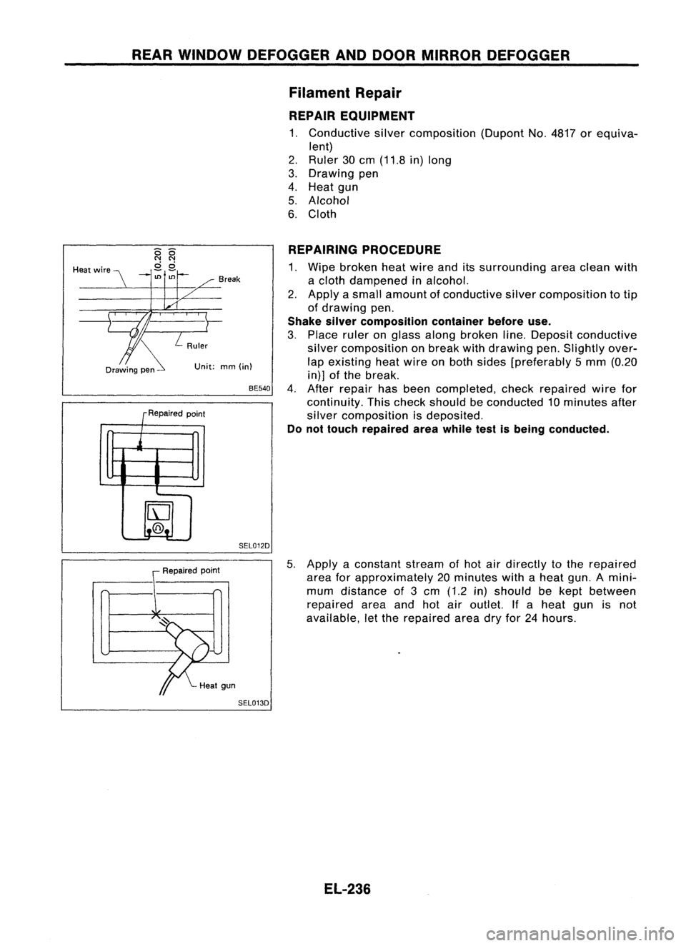
REARWINDOW DEFOGGER ANDDOOR MIRROR DEFOGGER
Filament Repair
REPAIR EQUIPMENT
1. Conductive silvercomposition (DupontNo.4817 orequiva-
lent)
2. Ruler 30cm (11.8 in)long
3. Drawing pen
4. Heat gun
5. Alcohol
6. Cloth
Unit: mm(in)
REPAIRING
PROCEDURE
1. Wipe broken heatwire anditssurrounding areaclean with
a cloth dampened inalcohol.
2. Apply asmall amount ofconductive silvercomposition totip
of drawing pen.
Shake silvercomposition containerbeforeuse.
3. Place ruleronglass along broken line.Deposit conductive
silver composition onbreak withdrawing pen.Slightly over-
lap existing heatwire onboth sides [preferably 5mm (0.20
in)] ofthe break.
4. After repair hasbeen completed, checkrepaired wirefor
continuity. Thischeck should beconducted 10minutes after
silver composition isdeposited.
Do not touch repaired areawhile testisbeing conducted.
BE540
SEL012D
Break
R .d
epalre point
j
IrJ
t..@.!.
-
--
Heat
wire
Repairedpoint
5.
Apply aconstant streamofhot airdirectly tothe repaired
area forapproximately 20minutes withaheat gun.Amini"-
mum distance of3cm (1.2 in)should bekept between
repaired areaandhotairoutlet. Ifa heat gunisnot
available, letthe repaired areadryfor24hours.
SEL013D
EL-236
Page 628 of 1701

NATS(Nissan Anti-Theft System)
Trouble Diagnoses (Cont'd)
SYMPTOM
SYSTEM REFERENCEPART Displayed"SELF- DIAGNOSTIC
PROCE-
(Malfunctioning NO.OFILLUSTRA-
•Blinking ofMIL*. •
Blinking ofMIL *.
DIAGRESULTS" on DURE
part ormode)
TIONONNEXT PAGE
•Engine willstart. •
Hard tostart
CONSULTscreen. (Reference
page)
engine.
System initialisation
has notyetbeen
F X
10
DISCORD, IMM- PROCEDURE 6
completed. ECM(EL-263)
ECM F X
Noise interference in
XMINGLE
NOISE PROCEDURE
7
communication line (EL-264)
Engine trouble data
DON'TERASE
and NATS trouble
BEFORECHECKING WORK
FLOW
data have been X
X
(EL-251)
detected inECM ENG
DIAG
SYMPTOM MATRIXCHART2
(Non self-diagnosis relateditem)
X:Possibility item
SYSTEM SYMPTOM
DIAGNOSTIC
PROCE-
(Malfunctioning partormode) DURE
NATS security indodoes notlight up.
(Referencepage)
NATS security indo
Open circuit between FuseandNATS IMMU
PROCEDURE8
X (EL-264)
Continuation ofinitialisation mode
NATS IMMU
DIAGNOSTIC SYSTEMDIAGRAM
NATS antenna amp.
PART
0 Key10chip (PART E5)
i-------
L---
--j)))
:
.
, ,
I~ .'
(((
NATS ignition
key
PART
E1,E2,E3, E4 IGN
PART C2~ +1./PART C1(MIL)
PART C4
ECM
..
........
................
:'
.......
PART F
D
IGN
EL-256
CONSULT
SEL466U
Page 636 of 1701
Self-diagnosticresults:
"MINGLE NOISE"displayed onCONSULT screen
m
T
Confirm SELF-DIAGNOSTIC RESULTS"MINGLENOISE"dis-
~ played onCONSULT screen.
NATS
(Nissan Anti-Theft System)
Trouble Diagnoses (Cont'd)
DIAGNOSTIC PROCEDURE 7
• SELF.DIAG RESULTS.
0
FAILURE DETECTED TIME
MINGLE NOISE 0
ERASE
II
PRINT
I
Turnofforremove anypossible noisesources.
SEL384U
• SELF.DIAG RESULTS.
0
FAILURE DETECTED TIME
MINGLE NOISE 0 Touch
"ERASE" onCONSULT SELF-DIAGNOSTIC RESULTS
screen.
ER~I PRINT
I
SEL385U
Start
engine.
OK
END
NG
DIAGNOSTIC PROCEDURE8
"NATS SECURITY IND.DOES NOTLIGHT UP"
m
o
UP
SIDE I~
....
EE3J
7.5A
SEL491U
Check
fuse(7.5A) inthe fuse box.
OK
NATS INITIALISATION
1) Fix the 7.5A fuseshown left
m.
2) Perform initialisation with
CONSULT.
For theoperation of
initialisation, referto"CON-
SUL Toperation manualNATS
V2.0".
NG
Replace fuse.
Turn ignition switch"OFF".
Start engine andturn ignition switch
"OFF".
Check NATSsecurity indoblinking.
OK
END
NG
EL-264
Page 709 of 1701
View
from
B FRONT
SUSPENSION
Stabilizer Bar(Cont'd)
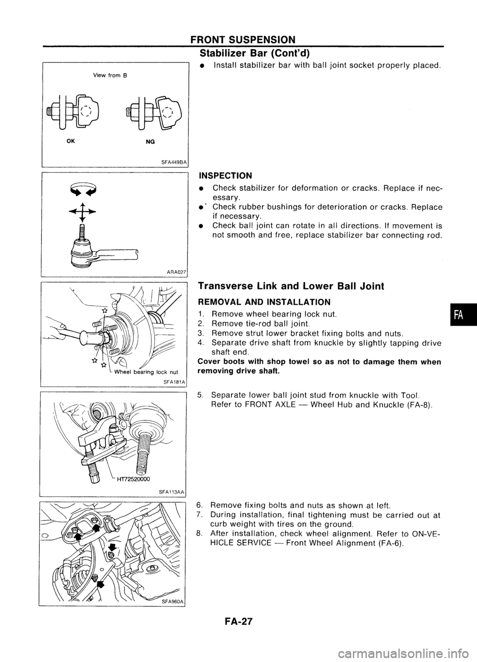
• Install stabilizer barwith balljoint socket properly placed.
OK NG
SFA449BA
ARA027 INSPECTION
• Check stabilizer fordeformation orcracks. Replace ifnec-
essary.
• Check rubber bushings fordeterioration orcracks. Replace
if necessary.
• Check balljoint canrotate inall directions. If
movement
is
not smooth andfree, replace stabilizer barconnecting rod.
SFA181A
SFA113AA Transverse
LinkandLower BallJoint
REMOVAL ANDINSTALLATION
1. Remove
wheelbearing locknut. •
2. Remove
tie-rodballjoint.
3. Remove
strutlower bracket fixingboltsandnuts.
4. Separate driveshaftfromknuckle byslightly tapping drive
shaft end.
Cover bootswithshop towel soas not todamage themwhen
removing driveshaft.
5. Separate lowerballjoint studfrom knuckle withTool.
Refer toFRONT AXLE-Wheel HubandKnuckle (FA-8).
6. Remove
fixingboltsandnuts asshown atleft.
7. During installation, finaltightening mustbecarried outat
curb weight withtires onthe ground.
8. After installation, checkwheel alignment. RefertoON-VE-
HICLE SERVICE -Front Wheel Alignment (FA-6).
FA-27
Page 749 of 1701
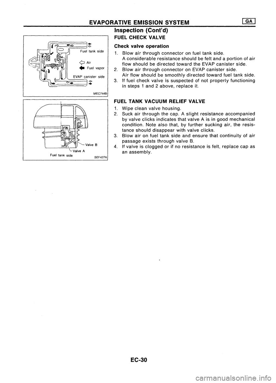
EVAPORATIVEEMISSIONSYSTEM
Inspection (Cont'd)
FUEL CHECK VALVE
~V""B
ValveA
Fuel tank side
..
"?
Fuel tankside
QAir
... Fuel vapor
EVAP canister side
..
MEC744B
SEF427N Check
valveoperation
1. Blow airthrough connector onfuel tank side.
A considerable resistanceshouldbefelt and aportion ofair
flow should bedirected towardtheEVAP canister side.
2. Blow airthrough connector onEVAP canister side.
Air flow should besmoothly directedtowardfueltank side.
3. Iffuel check valveissuspected ofnot properly functioning
in steps 1and 2above, replace
it.
FUEL TANK VACUUM RELIEFVALVE
1. Wipe clean valvehousing.
2. Suck airthrough thecap. Aslight resistance accompanied
by valve clicks indicates thatvalve Ais in good mechanical
condition. Notealsothat, byfurther sucking air,theresis-
tance should disappear withvalve clicks.
3. Blow aironfuel tank sideandensure thatcontinuity ofair
passage existsthrough valveB.
4. Ifvalve isclogged orifno resistance isfelt, replace capas
an assembly.
EC-30
