1995 NISSAN ALMERA N15 alternator
[x] Cancel search: alternatorPage 395 of 1701
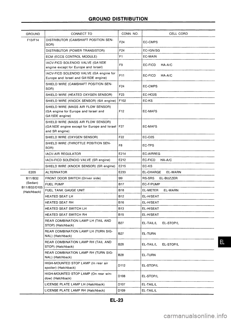
GROUNDDISTRIBUTION
GROUND CONNECT
TO CONN.
NO. CELLCORD
F13/F14 DISTRIBUTOR
(CAMSHAFTPOSITIONSEN-
F24 EC-CMPS
SOR)
DISTRIBUTOR (POWERTRANSISTOR) F24EC-IGN/SG
ECM (ECCS CONTROL MODULE) F1EC-MAIN
IACV-FICD SOLENOID VALVE(GA16DE
F9EC-FICDHA-A/C
engine exceptforEurope andIsrael)
IACV-FICD SOLENOID VALVE(GAengine for
F11 EC-FICD
HA-A/C
Europe andIsrael andGA15DE engine)
SHIELD WIRE(CAMSHAFT POSITIONSEN-
F24 EC-CMPS
SOR)
SHIELD WIRE(HEATED OXYGENSENSOR) F23
EC-H02S
SHIELD WIRE(KNOCK SENSOR) (GAengine) F102
EC-KS
SHIELD WIRE(MASS AIRFLOW SENSOR)
(GA engine forEurope andIsrael and F12 EC-MAFS
GA15DE engine)
SHIELD WIRE(MASS AIRFLOW SENSOR)
(GA 16DE engine exceptforEurope andIsrael F27
EC-MAFS
and SRengine)
SHIELD WIRE(OXYGEN SENSOR) F22
EC-02S
SHIELD WIRE(THROTTLE POSITIONSEN-
F8 EC-TPS
SOR)
IACV-AIR REGULATOR E214
EC-AIRREG
IACV-FICD SOLENOID VALVE(SRengine) E212 EC-FICD
HA-A/C
SHIELD WIRE(KNOCK SENSOR) (SRengine) E215 EC-KS
E205 ALTERNATOR E233
EL-CHARGE EL-WARN
B11/B32 FRONT
DOORSWITCH (Driverside) B9RS-SRSEL-BUZZER
(Sedan) FUELPUMP B17
EC-F/PUMP
B11/B32/D105
(Hatchback) FUEL
TANK GAUGE UNIT B18EL-METEREL-WARN
HEATED SEATLH B12EL-H/SEAT
HEATED SEATRH B16EL-H/SEAT
HEATED SEATSWITCH LH B13
EL-H/SEAT
HEATED SEATSWITCH RH B15
EL-H/SEAT
REAR COMBINATION LAMPLH(TAIL AND
B27 EL-TAILILEL-STOP/L
STOP) (Hatchback)
REAR COMBINATION LAMPLH(TURN SIG-
B27 EL-TURN
NAL) (Hatchback)
REAR COMBINATION LAMPRH(TAIL AND
B28 EL-TAILIL
EL-STOP/L
STOP) (Hatchback)
REAR COMBINATION LAMPRH(TURN SIG-
B28 EL-TURN
NAL) (Hatchback)
HIGH-MOUNTED STOPLAMP (Inrear air
D112 EL-STOP/L
spoiler) (Hatchback)
HIGH-MOUNTED STOPLAMP (Onrear win-
D108 EL-STOP/L
dow) (Hatchback)
LICENSE PLATELAMPLH(Hatchback)
D107EL-TAILIL
LICENSE PLATELAMPRH(Hatchback)
D109EL-TAILIL
EL-23
•
Page 426 of 1701

CHARGINGSYSTEM
Trouble Diagnoses
Before conducting analternator test,make surethatthebattery isfully charged. A3D-volt voltmeter and
suitable testprobes arenecessary forthe test. Thealternator canbechecked easilybyreferring tothe
Inspection Table.
Before starting, inspectthefusible link.
WITH IeREGULATOR
Burned-out
bulb.
Replace and
proceed to
"@".
Light "ON"
Light "OFF"
Connect
connector (S,
L) and
ground F
terminal
Engine
speed: 1,500 rpm
(Measure B
terminal
voltage)
Make sure
connector (S,L)is
connected
correctly.
(HITACHI
make)
'See
4)for grounding Fterminal.
(MITSUBISHI
make)
Check or
replace drive
belt.
Light "ON"
Light "OFF"
Disconnect
connector (S,
L) and
ground L
lead wire.
Engine
speed:
1,500 rpm
Lighting
switch "ON"
With
alternator sideLterminal
grounded. internalshortoccurs
when
+
diode isshort-circuited.
Light "ON
Dim
light
Light flickers
Bright light
Light
"ON"
Light
"OFF"
Ignition
switch "ON"
@
1) Use fully charged battery.
2) light: Charge warning light
ACG :Alternator partsexcept I'Cregulator
IC-RG :IC regulator
OK :IC-alternator isingood condition.
3) When reaching "Damaged ACG",remove
alternator fromvehicle anddisassembly, inspect
and correct orreplace faultyparts.
4) *Method ofgrounding Fterminal (HITACHI make
only)
Gasoline enginemodel
Contact tipofwire withbrush andattach
wire toalternator body.
~~~
;;z..'~~.~
~~~/j
S$.~~'
s<(r~, -
Brush liftwire
;;.. ~ Q<:::z"d,l'T7.
~ .. ~ ~-)o,IJ!"-f/
- -~~ C);
0~~/
'~-/i ~-,~
-~j~n
- <::::; -~ \•
'" 1A/-'
SEL030Z
5) Terminals
"S","l","B"
and
"E"
aremarked onrear cover ofalternator.
EL-54
Page 433 of 1701
CHARGINGSYSTEM
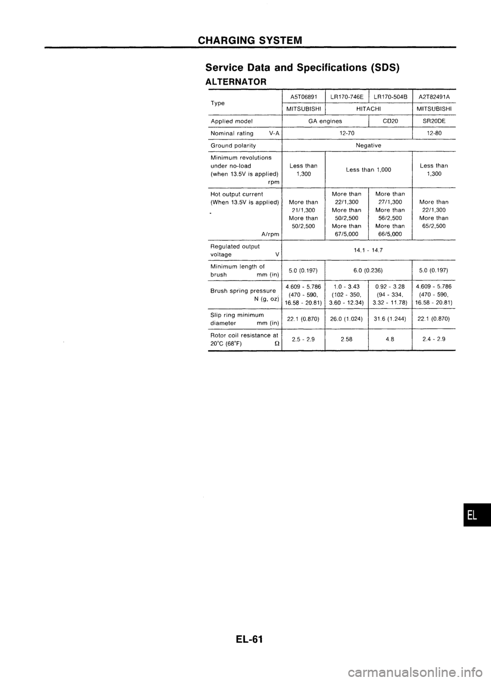
Service DataandSpecifications (SOS)
ALTERNATOR
A5T06891LR170-746E LR170-504B A2T82491A
Type MITSUBISHIHITACHIMITSUBISHI
Applied model GA
engines CD20SR20DE
Nominal rating V-A
12-70 12-80
Ground polarity Negative
Minimum revolutions
under no-load Less
than
Lessthan1,000 Less
than
(when 13.5Visapplied) 1,300 1,300
rpm
Hot output current More
than Morethan
(When 13.5Visapplied) More
than 22/1,300 27/1,300
Morethan
.
21/1,300
Morethan More
than 22/1,300
More than 50/2,500 56/2,500More
than
50/2,500 Morethan Morethan 65/2,500
A/rpm 67/5,000
66/5,000
Regulated output
14.1-14.7
voltage V
Minimum lengthof
50(0.197) 6.0
(0.236) 5.0(0.197)
brush mm(in)
Brush spring pressure 4.609
-5.786 1.0-343 0.92
-328 4.609-5.786
(470 -590, (102
-350, (94-334, (470
-590,
N (g, oz)
16.58 -20.81) 3.60
-12.34) 332-11.78) 16.58
-20.81)
Slip ringminimum
221(0.870) 26.0
(1.024) 31.6(1.244) 221(0.870)
diameter mm(in)
Rotor coilresistance at
2.5-2.9 258 4824
-29
20'C (68'F)
n
EL-61
•
Page 441 of 1701
HEADLAMP-Daytime LightSystem -
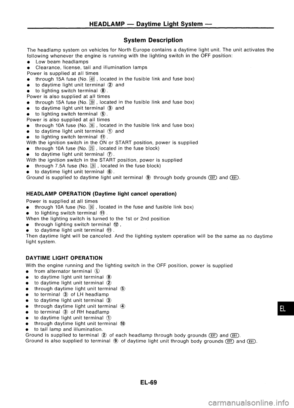
System Description
The headlamp systemonvehicles forNorth Europe contains adaytime lightunit.Theunitactivates the
following whenever theengine isrunning withthelighting switchinthe OFF position:
• Low beam headlamps
• Clearance, license,tailand illumination lamps
Power issupplied atall times
• through 15Afuse (No.
@ill,
located inthe fusible linkand fuse box)
• todaytime lightunitterminal @and
• tolighting switchterminal
@.
Power isalso supplied atall times
• through 15Afuse (No.~,located inthe fusible linkand fuse box)
• todaytime lightunitterminal
CID
and
• tolighting switchterminal
CID.
Power isalso supplied atall times
• through 10Afuse (No.~,located inthe fusible linkand fuse box)
• todaytime lightunitterminal
CD
and
• tolighting switchterminal @.
With theignition switchinthe ONorSTART position, powerissupplied
• through 10Afuse (No.~,located inthe fuse block)
• todaytime lightunitterminal (]).
With theignition switchinthe START position, powerissupplied
• through 7.5Afuse(No.
l2~,
located inthe fuse block)
• todaytime lightunitterminal @.
Ground issupplied todaytime lightunitterminal @through bodygrounds
@
and@D.
HEADLAMP OPERATION (Daytimelightcancel operation)
Power issupplied atall times
• through 10Afuse (No.~,located inthe fuse andfusible linkbox)
• tolighting switchterminal
@.
When thelighting switchisturned tothe 1stor2nd position
• through lightingswitchterminal @,
• todaytime lightunitterminal
@.
Then daytime lightwillbecanceled. Andthelighting systemoperation willbethe same asnodaytime
light system.
DAYTIME LIGHTOPERATION
With theengine running andthelighting switchinthe OFF position, powerissupplied
• from alternator terminal
CI>
• todaytime lightunitterminal
@
• todaytime lightunitterminal @
• through daytime lightunitterminal
CID
• toterminal
@)
ofLH headlamp
• todaytime lightunitterminal
CID
• through daytime lightunitterminal @
• toterminal
@)
ofRH headlamp
• todaytime lightunitterminal
CD
• through daytime lightunitterminal
@)
• totail lamp andillumination.
Ground issupplied toterminal
@
ofeach headlamp throughbodygrounds
@
and@D.
Ground isalso supplied toterminal @ofdaytime lightunitthrough bodygrounds
@
and@D.
EL-69
•
Page 444 of 1701
HEADLAMP-Daytime LightSystem -
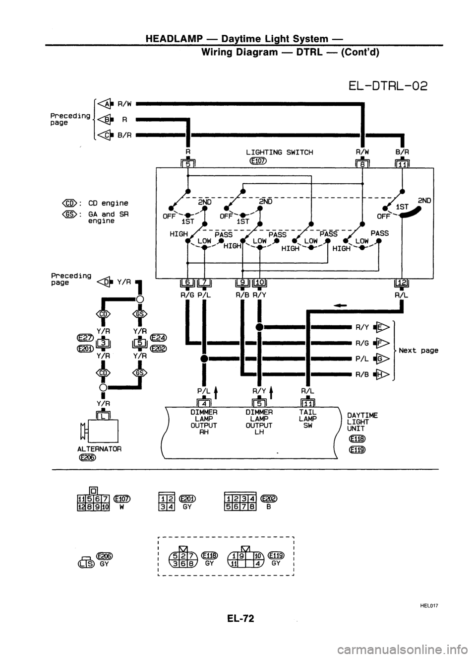
Wiring Diagram -DTRL -(Cont'd)
EL-DTRL-02
{~ RIW
I
Preceding
----Bt-
R
==I
page ~
~ BIR --------------
I
R LIGHTINGSWITCH RIWBIR
m
Irf1iI
@:
CDengine
@:
GAand SR
engine
--2NO---
--2ND--------------
OFF- .......
1ST
HIGH PASS PASS-
-PASS --
PASS
'- LOW --HIGH '-LOW __ '-LOW '-LOW
_.... _....HIGH-....... HIGH-.......
2ND
ext page
~
RIL
DAYTIME
LIGHT
UNIT
~
(ffiID
RIL
wf1]
TAIL
LAMP
SW
I
.....
I
R/Y
lit>
RIG ~
N
PIL
-@>
RIB ~
RIY
t
m
DIMMER LAMP
OUTPUT
LH
e--II-
I
PIL
t
m
DIMMER LAMP
OUTPUT
RH
~~
1biJJ~
RIG
PIL RIBRIY
L._._e
ALTERNATOR
~
Preceding
.....-;::;1.
page ~YIR
1
~t
YIR YIR
~ IctJl 1r1J1~
@ID=r =r~
Y/R Y/R
tJ
I
Y/R
d
Ffm~
ffi
GY
~~
~B
r---------------------,
@lID
(~) GY
I
I
: ~ @ID~
I ~
GY
\llLt:W
GY
I
I I
L
~
HEl017
EL-72
Page 446 of 1701
HEADLAMP-Daytime LightSystem -
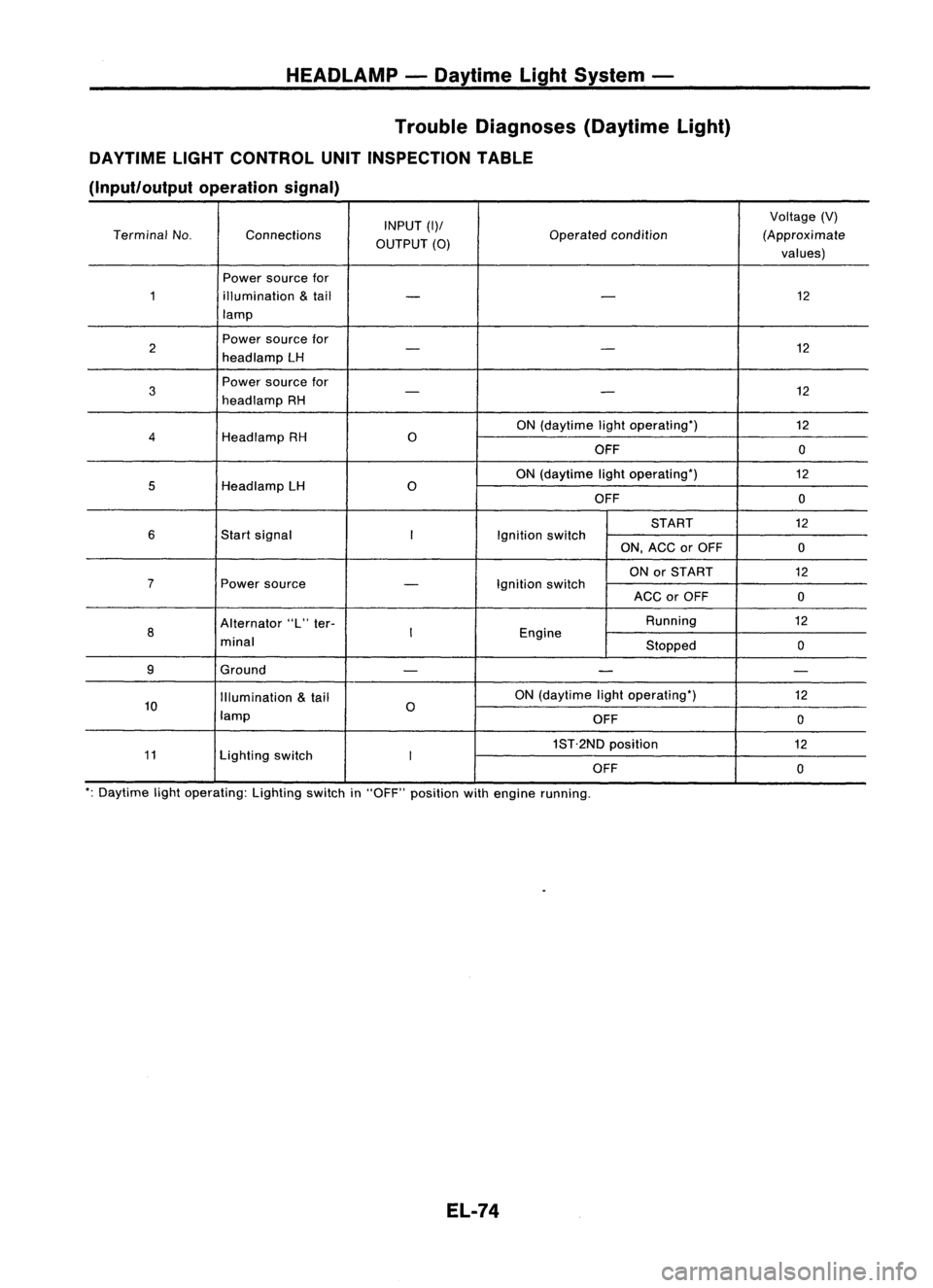
Trouble Diagnoses (DaytimeLight)
DAYTIME LIGHTCONTROL UNITINSPECTION TABLE
(Input/output operationsignal)
INPUT
(1)/
Voltage
(V)
Terminal No. Connections
OUTPUT
(0)
Operated
condition (Approximate
values)
Power source for
1 illumination
&
tail
- -
12
lamp
2 Power
source for
12
- -
head lamp LH
3
Power
source for
12
-
-
head lamp RH
ON(daytime lightoperating')
12
4
HeadlampRH
0
OFF 0
ON (daytime lightoperating') 12
5
HeadlampLH
0
OFF 0
START 12
6
Startsignal
I
Ignitionswitch
ON,ACC orOFF
0
ON orSTART
12
7
Powersource
-
Ignition
switch
ACCorOFF
0
Alternator "L"ter- Running
12
8
I
Engine
minal Stopped0
9 Ground
- - -
Illumination
&
tail ON
(daytime lightoperating')
12
10 lamp
0
OFF 0
1ST.2ND position
12
11 Lightingswitch
I
OFF 0
': Daytime lightoperating: Lightingswitchin"OFF" position withengine running.
EL-74
Page 510 of 1701
WARNINGLAMPSANDBUZZER
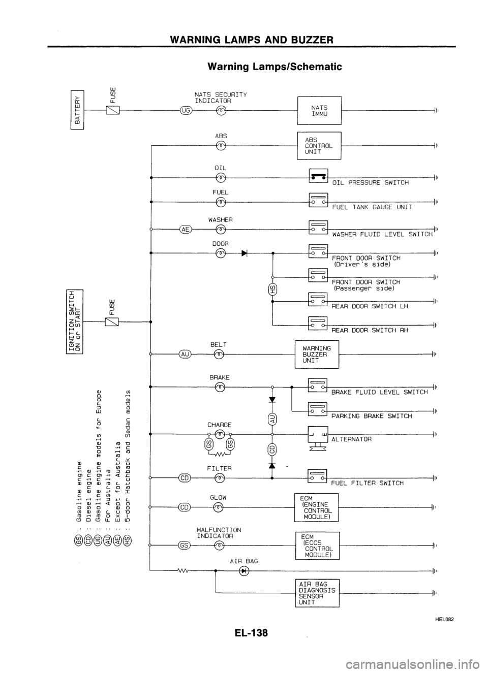
Warning Lamps/Schematic
>-
[[
W
f-
f-
CD
w
(f)
:J
l.L
UG
NATS
SECURITY
INDICATOR
NATSIMMU
ABS ABS
CONTROL
UNIT
OIL OILPRESSURE SWITCH
FUEL
FUELTANKGAUGE UNIT
WASHER
WASHERFLUIDLEVELSWITCH
DOOR
FRONTDOORSWITCH
(Driver's side)
FRONT DOORSWITCH
(Passenger side)
REAR ODOR SWITCH LH
ALTERNATOR PARKING
BRAKESWITCH
FUEL FILTER SWITCH
=
BRAKE
FLUIDLEVEL SWITCH
REAR
ODORSWITCH RH
=
WARNING
BUZZER
UNIT
=
ECM (ECCS
CONTROL
MODULE)
ECM
(ENGINE
CONTROL
MODULE)
I
U
f- W
H (f)
3:f-
:J
(f)[[
l.L
Zf-
O(f)
H
f-L
HO
Z
BELT
C!JZ
HO
BRAKE
Q)
(I)
D.
rl
0
Q)
L
D
::J
0
W
E
L
C
0
ro
""-
D
Q)
(I)
(f)
rl
Q)
ro
D
D
'M
C
0
rl
ro
E
ro
L
~
Q) Q)
.....
u
C C
(I)
ro
.M
Q)
.M
ro
::J
.0
OJ
C
OJ
.M
c
.M
C
rl
U
Q)
OJ
Q)
ro
L
+'
C
L
0
ro
Q) Q) Q)
.....
""-
I
C C
(I)
GLOW
.M
rl
.
M
::J
.....
L
rl
Q)
rl
0
0
(I)
0
Q)
0
(I)
Q)
(I)
L
u
D
ro
.M
ro
0
x
I
C!J
0
C!J
l.L
W
lD
MALFUNCTION
@@~@@@
INDICATOR
AIRBAG
AIRBAG
DIAGNOSIS
SENSOR
UNIT
HEL082
EL-138
Page 513 of 1701
WARNINGLAMPSANDBUZZER
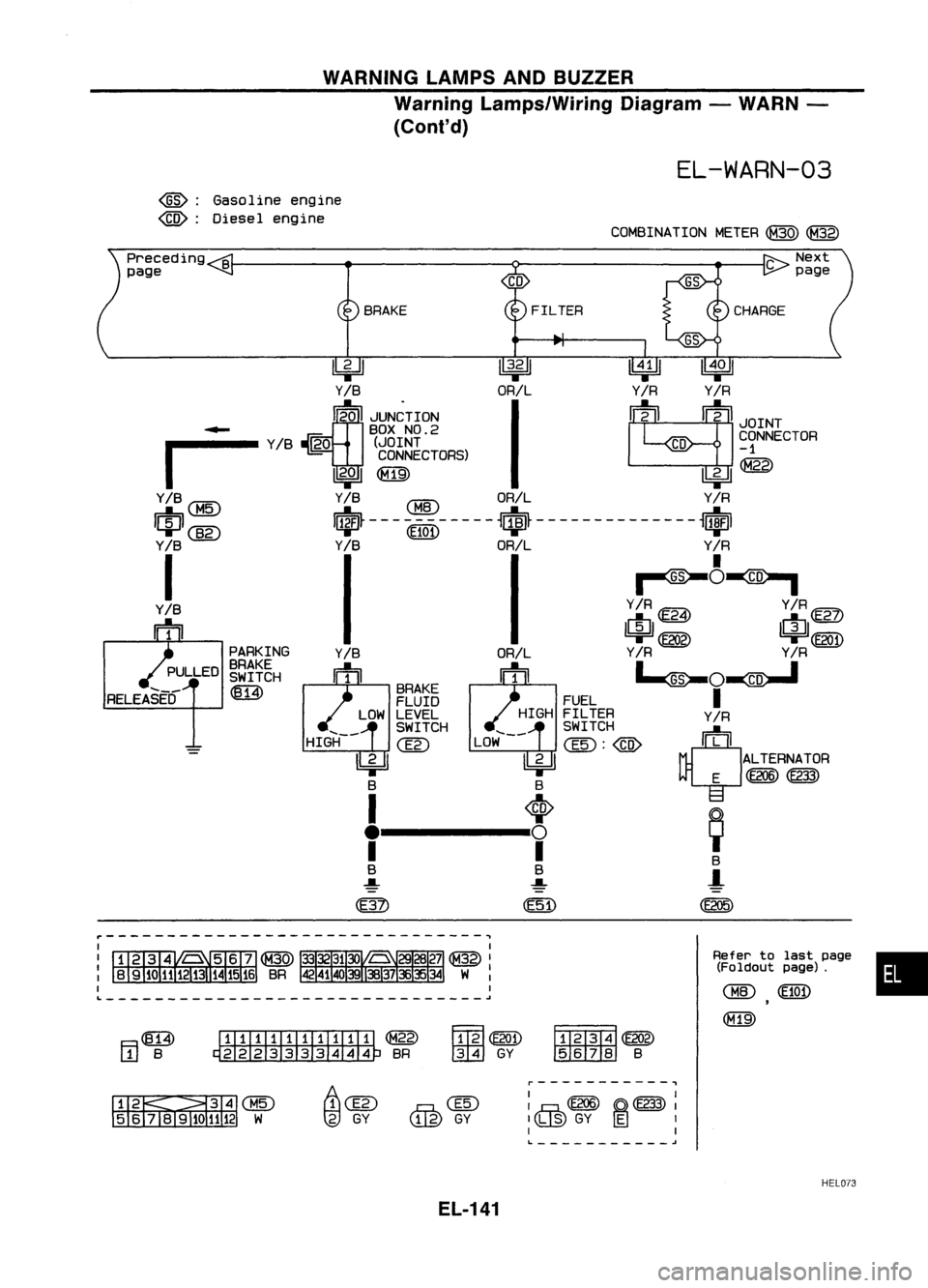
Warning Lamps/Wiring Diagram-WARN -
(Cont'd)
EL-WARN-03
~: Gasoline engine
~: Diesel engine
COMBINATIONMETER~~
•
Refer
tolast page
(Foldout page).
CHID
(E10
1)
(M19)
FILTER
~~
IIDID:IID
B
~~
tml
GY
BRAKE
....
_-
HIGH
ITIillJIIIIIIII ~
~BR
4=U
~
llWJ
Y
IB
ORILY
IR
Y
IR
~20 JUN~TION
I
~2
m
JOINT
~ BOXNO.2
r
Y
IB
~O (JOINT
CD
~ONNECTOR
CONNECTORS) ~
I
2..a
I
~@
Y/B
CBID
ORIL Y/R
I~I
@g)
I$~-- -CEl0l)- -- --
~$~ ----- --- -- ----
~ufJl
Y
IB
Y
IB
ORIL Y
IR
I
II~~~
Y/B Y/R~ Y/R@Z)
m1 I~II~I
'=r ~ '=rCE2Q1)
PARKING Y
IR
Y
IR
BRAKE •_ _.
SWITCH
~O~
~ BRAKE
I
FLUID FUEL
LOW LEVEL HIGHFILTER Y/R
~~~~CH LOW~-- ~~~~~H
@)
rn11:"1
II 2 II II2 II ALTERNATOR
T T
E
@@@)
f---t, ~
B B B
..... ..... -l
(E205)
Preceding
B
page
F.=I~
L.!J
B
....
_-
RELEASED
~-------------------------------~
L ~
Ii\Clli
tg)
GY
@
GY
r-----------.,
I I
I
,.hh
(E206) ~(E233)
I
Ilh,@
GY~
1
I I
L. -'
HEL073
EL-141