1995 NISSAN ALMERA N15 alternator
[x] Cancel search: alternatorPage 517 of 1701
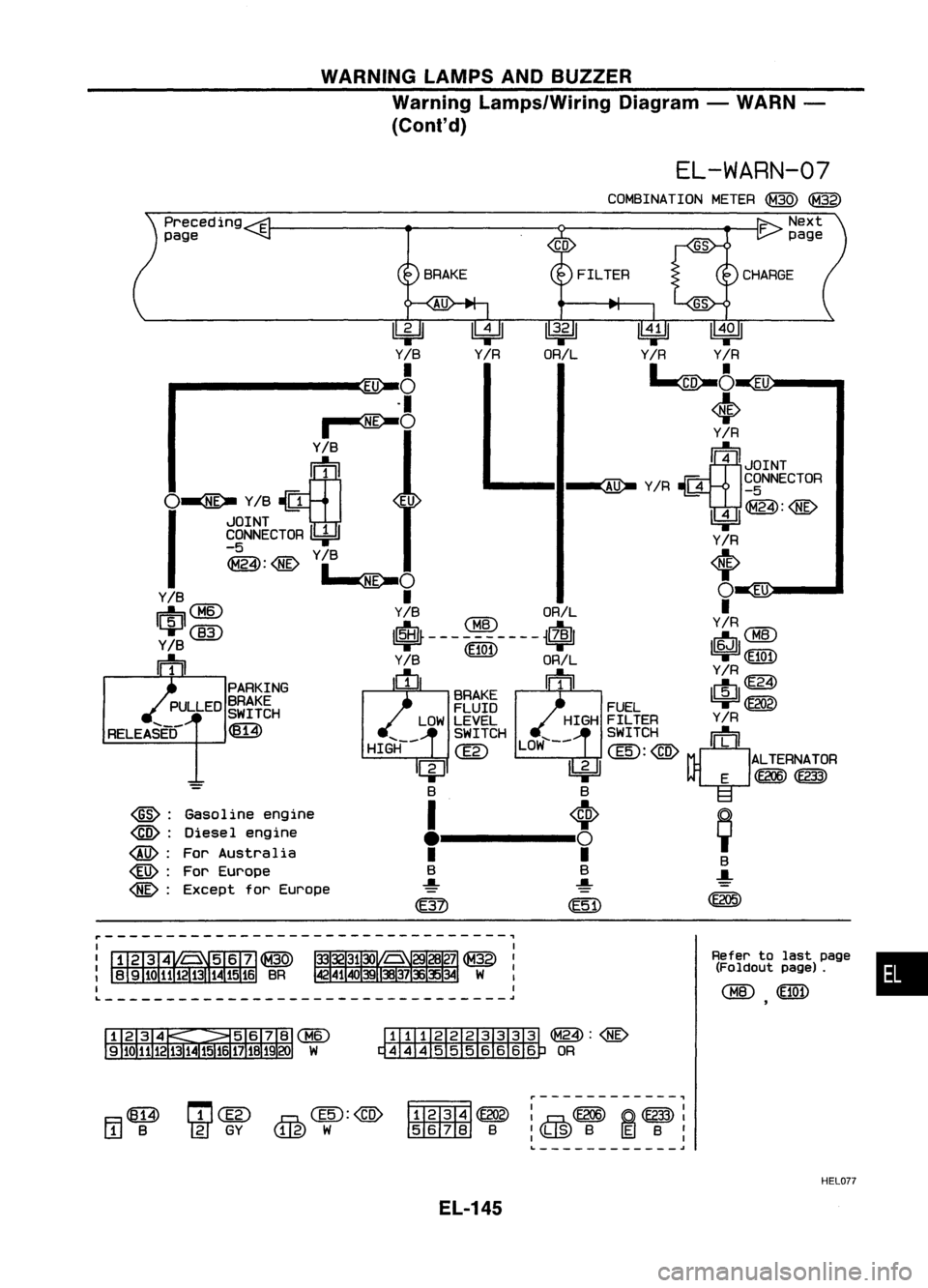
WARNINGLAMPSANDBUZZER
Warning Lamps/Wiring Diagram-WARN -
(ConI' d)
EL-WARN-07
•
Refer
tolast page
(Foldout page).
<:BID
FILTER
8RAKE
Gasoline engine
Diesel engine
For Australia
For Europe
Except forEurope
Preceding
E
page
@:
@:
@:
@:
@:
lbjJ
~~~
V8 ~A
Yffl
VR
EU ~
~
EU
.1 ~
~O ~
I -
Y/R
Y/8 ~
ffi
~4JOINT
" __ II~ Y
IR ~
~gNNECTOR
O~
Y
18
.Ji1
EU
IU"'i'A\A'i"E'..
~ IWI~:~
JOINT
=r'
Y/R
~:@
Y/8
4
1..«-0 T
Y/8
I ()
EU
1$1
@
Y18
CHID
ORIL Y'R
@)
It~----------i$1
~~6J(][)
Y/8 $100~
-1
ffl
WL ~
11111
W
m
Y/R
PARKING 18RAKE 1 I~I~
PULLED ~~~~~H FLUIDFUEL~
LOW LEVEL HIGHFILTER Y
IR
RELEASED ~ SWITCH
'-- LOW'--SWITCH
rn':' I
HIGH
@
@:@
ALTERNATOR
I4J ~
E
CE2(6) ~
8 8
11---1; ~
I I
8
8 8...
-!- .....
=
~ CE51)CE205)
r---------------------------------~
~~:@
~ OR
F.=l~
L!.J
8
m@
~@:@)
'IN
GY
u.w
W
~------------.,
ffi2i3T4l ~:~
CE2(6) ~~ :
rn::tilllID
8
I
\b.@
BE8
I
I I
L
.I
HELD??
EL-145
Page 520 of 1701
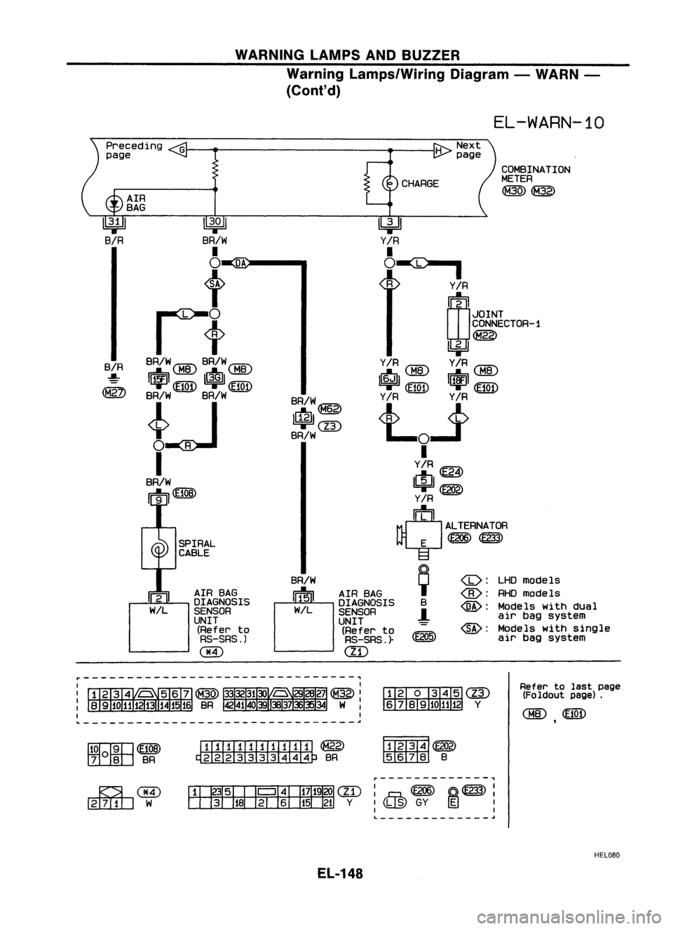
WARNINGLAMPSANDBUZZER
Warning Lamps/Wiring Diagram-WARN -
(Cont'd)
EL-WARN-10
COMBINATION
METER
@)@>
LHD models
RHD models
Models withdual
air bag system
Models withsingle
air bag system
(D:
(8):
@:
@:
B
-!
(E205)
~
Y/R
•
o~
R Y/R
rn
2
JOINT
CONNECTOR-1
~
I!:jJJ
Y/R
I"UD\
Y/R
I'TIO\
I$II~ ~~
Y/R Y/R
t.o.i
I
Y/R ~
.-4-,~
~
ViR ~
O
L
ALTERNATOR
E @ID @ID
~
BR/W~
I~I@)
BR/W
BR/W
O~
AIRBAG
111511 DIAGNOSIS
W/L SENSOR
UNIT
(Refer to
RS-SRS.).
em
G
SPIRAL
CABLE
~
BR/W
•
t-:lDiAA:---.
It
BR/W
I"UD\
BR/W
I'TIO\
1i1tn~~~
!!JI
3.G
I
BR/W BR/W
t~
I
BR/W
m~
B/R
~
~-------------------------------,
~-------------------------------~
Refer
tolast page
(Fo ldout page).
@
ITlIIillIillIII
@
~ BR
~~
~B
~-------------.,
~@
[g]lJTIJ
W
:
~
IrnGY ~I
I I
L
.J
HEL080
EL-148
Page 792 of 1701
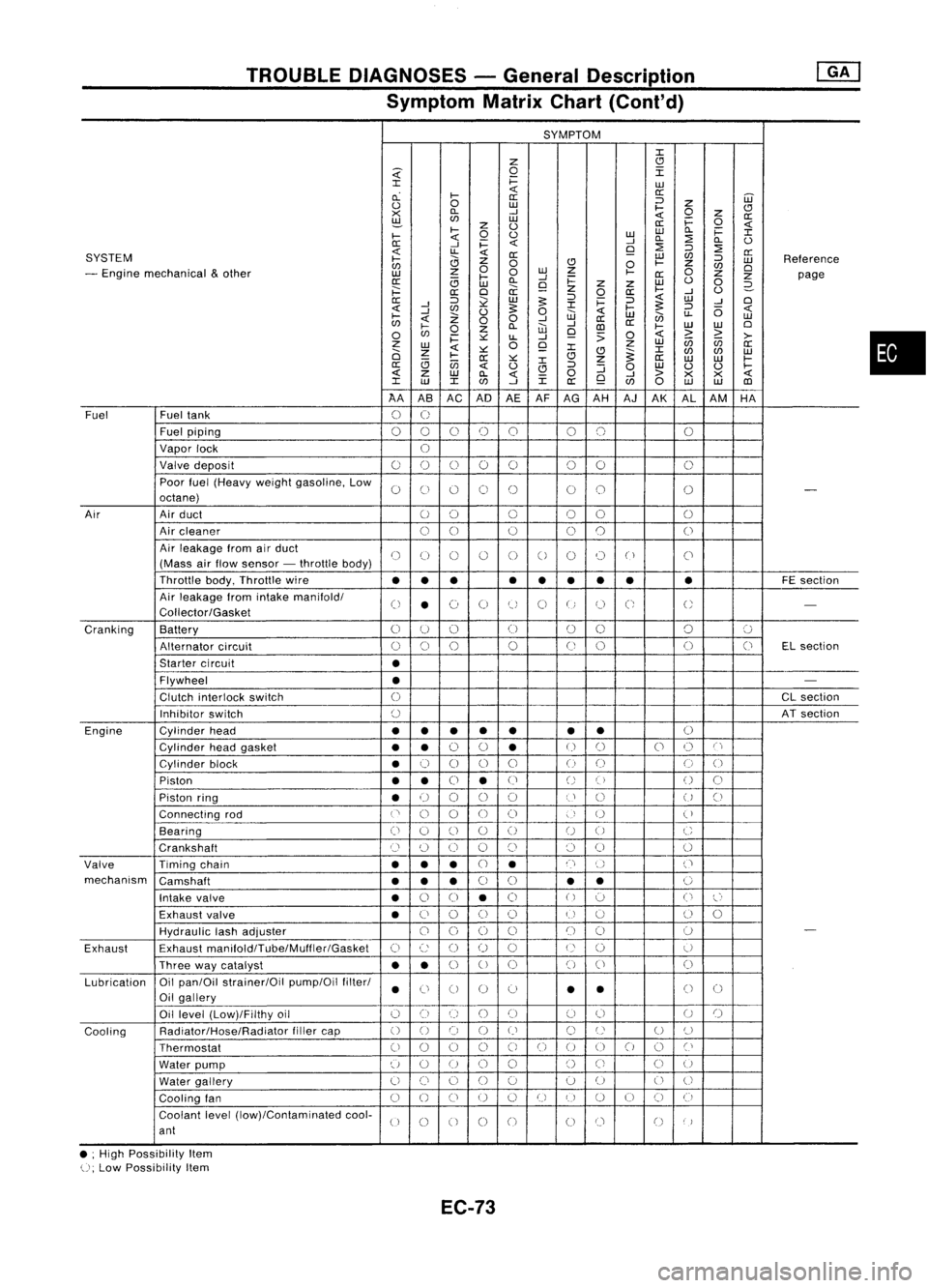
TROUBLEDIAGNOSES -General Description
Symptom MatrixChart(Cont'd)
SYMPTOM
J:
Z
CJ
~
0
I
J:
i=
LU
cL
I-
«
a:
a: ::J
UJ
0
0
LU
I-
Z
CJ
><
D..
-'
«
0
z
a:
~
LU
i=
0
z
0
a:
«
I-
0
0
LULU
D..
i=
J:
I-
«
-'
D..
:2
D..
0
0:
-'
i=
«
9
:2
::J
:2
SYSTEM
«
LL
«
0:
LU
C/J
a:
I-
0
Z
0
CJ
0
I-
Z
::J
LU
Reference
C/J
0
C/J
0
- Engine mechanical
&
other
z
0
LU
Z
I-
0
LU
I-
-'
0:
Z
Z
page
0:
(3
LU
D..
9
i=
z
Z
LU
0
0
2-
;:::
a:
0
a:
z
0
a:
I-
-'
0
0:
::J
~
LU
5:
::J
i=
::J
«
LU
-'
0
-'
J:
5:
«
-'
C/J
0
5:
0
«
I-
::J
(5
«
I-
Z
W
LU
en
LL
LU
C/J
«
00
-'
-'
a:
a:
0
I-
0
Z
D..
W
CD
I-
LU
LU
0
C/J
i=
~
LL
-'
9
:>
0
«
>
~
>-
z
0
Z
LU
(ij
C/J
a:
LU
«
~
9
J:
J:
0
Z
CJ
~
C/J
C/J
LU
I-
0:
~
CJ
Z
a:
LU LU
I-
(3
(jj
J:
a:
«
0
CJ
::J
:J
0
LU
0 0
I-
«
z
LU
D..
«
0
-'
>
><><
«
J:
LU
J:
C/J
-'
J:
a:
9
C/J
0
LU LU
CD
AA ASAC AD
AEAF
AG AH AJAK ALAM HA
Fuel Fueltank
0
U
Fuel piping
00 0
()
0 00 0
Vapor lock
U
Valve deposit
00 000 00
0
Poor fuel(Heavy weightgasoline, Low
0
C)
0 0
()
00
0
-
octane)
Air Airduct
00 0
00
0
Air cleaner
00
0
0
0
0
Air leakage fromairduct
()
(J
()
()
0
0
0 0
("
)
C'
(Mass airflow sensor -throttle body)
Throttle body,Throttle wire
••• •
••
•• •
FE
section
Air leakage fromintake manifold/
0
•
(~)
0
tJ
0
U
C;
U
-
Collector/Gasket
Cranking Battery
0
U
()
(J
00 0
':J
Alternator circuit
()
0
0
0
(J
0 0
(J
ELsection
Starter circuit
•
Flywheel
•
-
Clutch interlock switch
0
CL
section
Inhibitor switch
()
ATsection
Engine Cylinderhead
••
• •
• •
•
()
Cylinder headgasket
••
0
0
•
U
()
0
()
C'
Cylinder block
•
0
0 0
0
()
(J
0
0
Piston
••
0
•
(J
()
()
()
0
Piston ring
•
U
00
0
U
()
U
()
Connecting rod
('
0
0
00
)
U
(
)
Bearing
(i
0
()
0
()
U
0
C
Crankshaft
Cl
(~)
0 0
()
()
0
0
Valve Timingchain
•••
CJ
•
n
()
('
mechanism Camshaft
•••
0
0
•
•
0
Intake valve
•
0
0
•
0
()
':J
0
l~'
Exhaust valve
•
C)
0
()
()
U
u
()
0
HydraUlic lashadjuster
00
0
0
()
()
0
-
Exhaust Exhaust
manifoldlTube/Muffler/Gasket
C)
c:
()
()
0
U
()
U
Three waycatalyst
••
0
U
0 0
()
0
Lubrication Oil
pan/Oil strainer/Oil pump/Oilfilter/
•
Ci
0 0
0
•
•
()
0
Oil gallery
Oil level (Low)/Filthy oil
()
0
()
()()
(J
0
U
()
Cooling Radiator/Hose/Radiator
fillercap
()
0 0
()
()
C)
U
U
()
Thermostat
00
0
0
C)
0
()
00
0
Cl
Water pump
u
0
U
0
0
()
Ci
C)
U
Water gallery
U
()
0
()
0 0
U
0
U
Cooling fan
0
()
CJ
U
0
U
I)
U
()
CJ
(i
Coolant level(low)/Contaminated cool-
U
0
0 0
0
00
()
)
ant
• ;High Possibility Item
U;
Low Possibility Item
EC-73
•
Page 995 of 1701
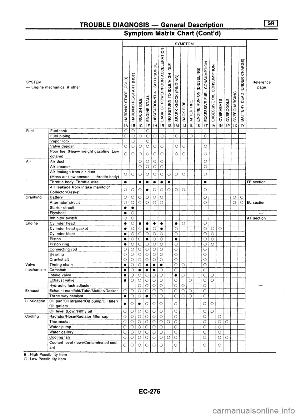
TROUBLEDIAGNOSIS -General Descrip_tio_n
1s_R_1
Symptom MatrixChart(Cont'd)
SYMPTOM
z
0
i=
«
W
a:
z
w
w
w
CJ
CJ
....J
....J
0
Z
a:
w
i=
0
a:
(.)
9
8
«
0.. i=
:I:
::J
(.)
z
:2
i='
en
«
:I:
8
:J
0..
(.)
Q
0
f:::.
CJ
:J
:2
a:
a:
:E
z
w
en
SYSTEM
....J
~
0
0
en
z
:J
w
Reference
0
0..
W
a
w
en
Cl
- Engine mechanical
&
other
I-
en
0
z
0
z
z
S:?-
a: 0..
....J
e-
(.)
0
page
I-
«
l-
ii.
9
~
....J
(.)
2-
a:
~
«
w
0
z
w
CJ
Cl
....J ....J
:.:::
0
:J
....J
Z
«
....J
u.
~
I-
(.)
u..
0
a
«
I-
w
«
Z
0
z
enen
w
en
a:
....J
I-
0..
Z
0
WW
:J
W
W
I-
....J
a:
Cl
0 0
9
en
0
a:
z
a:a:
a:
> >
«
0
«
>-
i=
u..
:J
:.:::
ii:
enen
0
:I:
Z Z
W
0
l-
ii:
w w
a:
Ci Ci
:I:
Z
«
w
:.:::
a:
z
en
en
:I:
(.)
(.)
w
CJ
a
I-
:.:::
a:a:
:.:::
w
a
w
w
a:
a:a:
~
a:
a:
:J
en
(.)
«
(.)
I-
(.)
(.)
w
w
w
« «
0
z
w
«
0
0..
«
u..
Z
x x
>>>
«
:I: :I:
a:
w
:I:
....J
Z
en
(l)
«
w w
w
00 0
(l)
1A 1B
1C 1F1H
1R 1S
1M 1J1L1K
1T
1V
1N
1P1X 1Y
Fuel Fueltank
00 0
Fuel piping
00 0000 000
0
Vapor lock
00
Valve deposit
000 000 00 0
Poor fuel(Heavy weightgasoline. Low
0000 00 00
0
-
octane)
Air Airduct
00 00 0
Air cleaner
0
0
00 0
Air leakage fromairduct
00 00 00 0
0 0
0
(Mass airflow sensor -throttle body)
Throttle body.Throttle wire
•
•
•
•
• •
•
FE
section
Air leakage fromintake
manifoldl
00 0
•
0
0 0
00 0
-
Coliector/Gasket
Cranking Battery
0
0
00 0
0 0
0
0
Alternator circuit
00
00
0
0 0
00
EL
section
Starter circuit
••
Flywheel
•
0
-
Inhibitor switch
00
ATsection
Engine Cylinderhead
•
0
•
•
••
•
0
0
Cylinder headgasket
•
0
()
•
0
•
0
0
00
Cylinder block
•
0
()
0 00 0 00
Piston
•
0
0
•
0
0
•
0
0
Piston ring
•
0
00 0
0 0 00
Connecting rod
00 00
00 0 0
Bearing
000 000 0
0
Crankshaft
00
0 0
0
0 0
0
Valve Timingchain
•
0
0
••
•
0
0 0
mechanism Camshaft
•
0
•• •
0
0 0
Intake valve
•
0
00 0
0
•
0
0
0
Exhaust valve
•
0
00 00 0000
Hydraulic lashadjuster
0000
'0
0 0
-
Exhaust Exhaust
manifoldlTube/Mulfler/Gasket
00
00 0
0
00
0 0
Three waycatalyst
•
0
0
•
0
0 000 0
Lubrication Oilpan/Oil strainer/Oil pump/Oilfilterl
000
0
0 0
0
Oil gallery
••
Oil level (Low)/Filthy oil
00 0000
0 0
0
Cooling Radiator/Hose/Radiator fillercap
00
0 00
0 0 00
Thermostat
00
00 0
0 00 0
00
Water pump
000 000 0 0
0
Water gallery
00 00 00
0 0
0
Cooling fan
00 0
00
0 0
0 0
0
0
Coolant level(low)/Contaminated cool-
00
0000
0 0
0
ant
• ;High Possibility Item
0; Low Possibility Item
EC-276
Page 1109 of 1701
TROUBLEDIAGNOSES
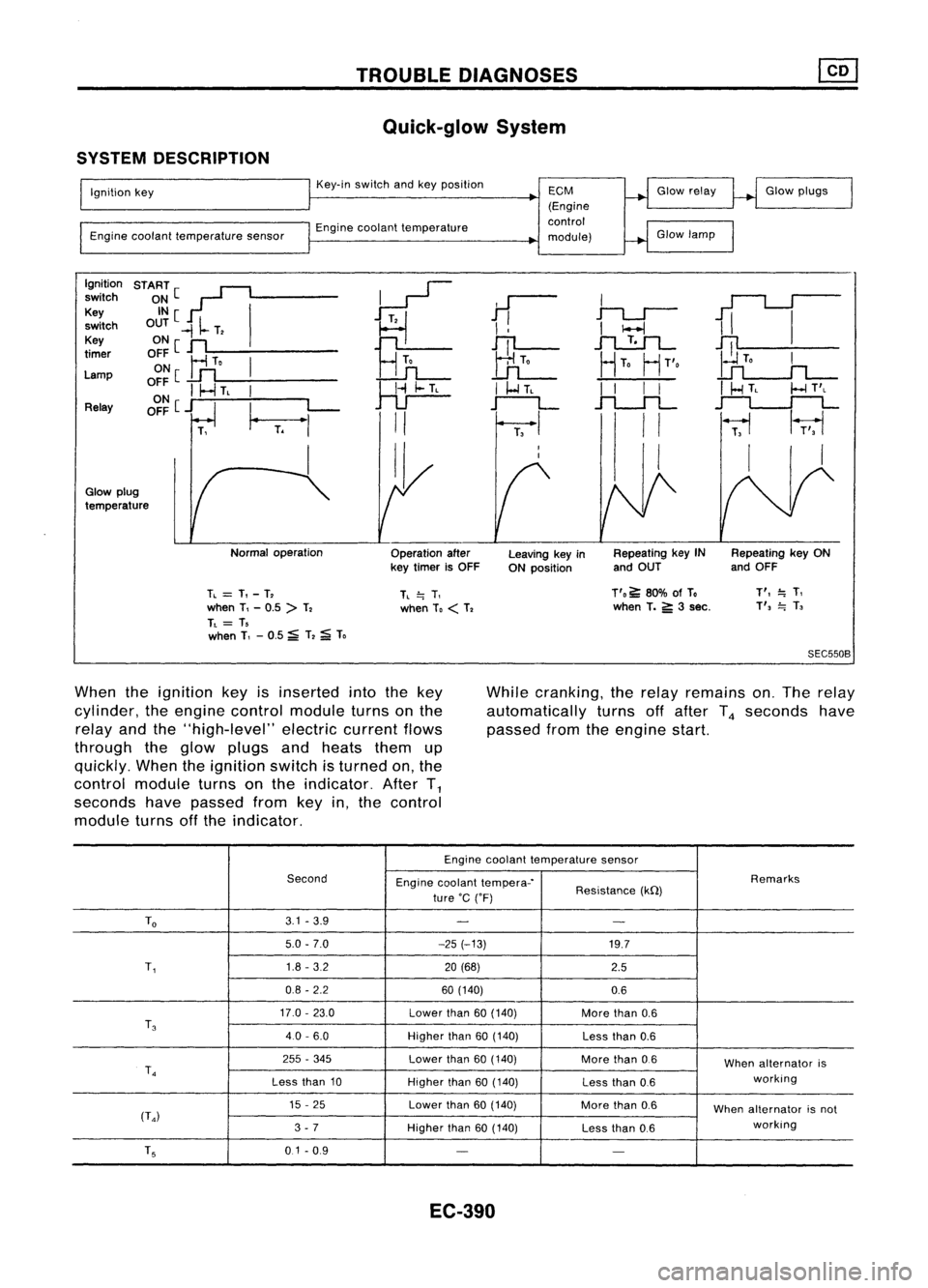
Quick-glow System
SYSTEM DESCRIPTION
Ignition key
Engine coolant temperature sensorKey-in
switch andkeyposition
Engine coolant temperature
ECM
(Engine
control
module) Glow
relay
Glow lamp Glow
plugs
Ignition START[~
~
switch
~~[ I
11
I
1iI
Key
~
switch OUT
-II-
T,
I
!
I
I-l
Key ONe
n
Hn
JTl-
.1"l....!:.1L-
~
timer
OFF
Ir1
To
I
UL
HTo
HT'o
Lamp ON
[
..Lfl
o~~
I
I-.J
TL
I
~
I
I-l
TL
I
I
I
I
I
HTL
I-l
T'L
Relay OFF
[j
I_
L-
r--L
.f"l.-.JL
~
T.
"'
II
I
II
~
1r;,1
I II I
I,
Glow plug
temperature
Normaloperation
Operationafter
key timer isOFF Leaving
keyin
ON position Repeating
keyIN
and OUT Repeating
keyON
and OFF
TL
=
T,-T,
when T,-0.5 >T,
TL
= T,
when T,-0.5 ~T,
;a;
To
TL
=.
T,
when To
<
T, T'o
~80% ofTo
when T.
5':
3sec.
T',
=.
T,
T',
=.
T,
SEC550B
When theignition keyisinserted intothekey
cylinder, theengine control module turnsonthe
relay andthe"high-level" electriccurrentflows
through theglow plugs andheats themup
quickly. Whentheignition switchisturned on,the
control module turnsonthe indicator. AfterT
1
seconds havepassed fromkeyin,the control
module turnsoffthe indicator. While
cranking, therelay remains on.The relay
automatically turnsoffafter T
4
seconds have
passed fromtheengine start.
Engine coolant temperature sensor
Second Enginecoolant tempera-' Remarks
ture 'C('F) Resistance
(kQ)
To
3.1
-3.9
- -
5.0 -7.0 -25(-13)
19.7
T,
1.8
-3.2
20(68)
2.5
0.8 -2.2 60(140)
0.6
17.0 -23.0
Lowerthan
60(140)
Morethan
0.6
T
3
40-6.0
Higherthan
60(140)
Lessthan
0.6
255 -345
Lowerthan
60(140)
Morethan
0.6
Whenalternator is
T
4
working
Less than
10
Higherthan
60(140)
Lessthan
0.6
15 -25
Lowerthan
60(140)
Morethan
0.6
Whenalternator isnot
(T
4)
working
3 -7
Higherthan
60(140)
Lessthan
0.6
T
5
0.1-0.9
- -
EC-390
Page 1117 of 1701
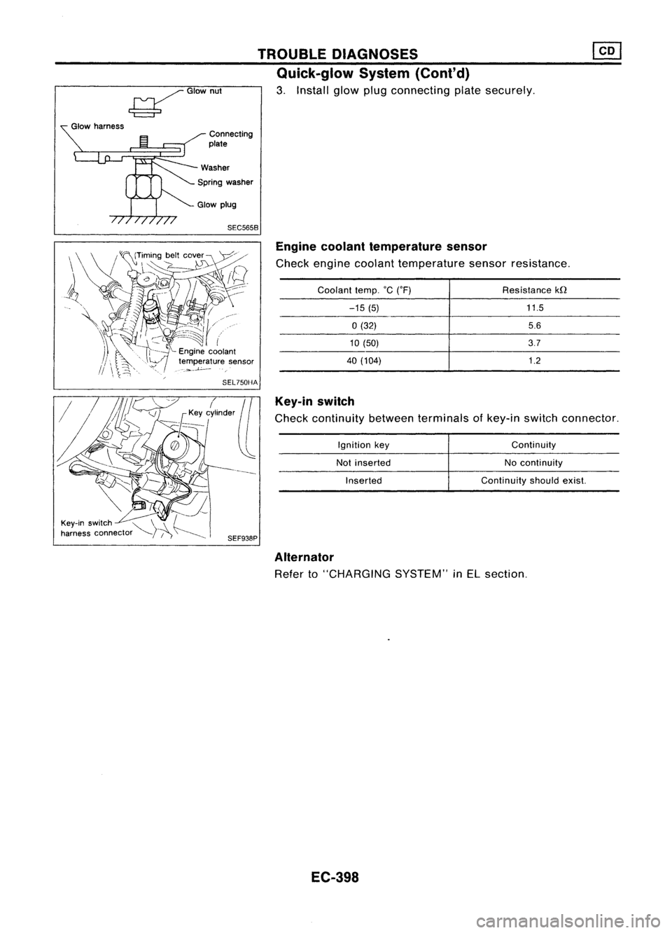
SEC5658Enginecoolant temperature sensor
Check engine coolant temperature sensorresistance.
Key-in switch
Check continuity betweenterminals ofkey-in switch connector.
11.5
5.6
3.7
1.2
Resistance
kfl
Continuity
No continuity
Continuity shouldexist.
Ignition
key
Not inserted
Inserted
Coolant
temp.°C('F)
-15 (5)
0(32)
10 (50)
40 (104)
TROUBLE
DIAGNOSES
Quick-glow System(Cont'd)
3. Install glowplugconnecting platesecurely.
Connecting
plate
Spring washer
~GIOwnut
Glow harness
Alternator
Refer to"CHARGING SYSTEM"inEL section.
EC-398
Page 1151 of 1701
ENGINECOOLING SYSTEM
IiJ
6.28 -8.34 (0.641 -0.851, 55.6-73.8)
SEC.
210 Water
Pump
~ 6.28 -8.34 (0.641 -0.851, 55.6-73.8)
WaterpumppUlley
l
~Liquid gasket
~ N.m(kg-m, in-Ib)
SLC989AB
•
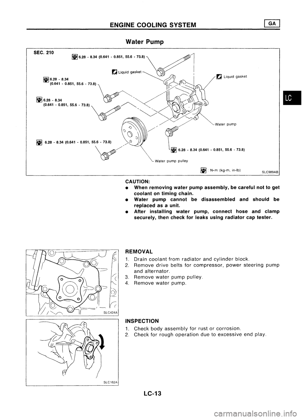
CAUTION:
• When removing waterpumpassembly, becareful nottoget
coolant ontiming chain.
• Water pumpcannot bedisassembled andshould be
replaced asaunit.
• After installing waterpump, connect hoseandclamp
securely, thencheck forleaks using radiator captester.
REMOVAL
1. Drain coolant fromradiator andcylinder block.
2. Remove drivebeltsforcompressor, powersteering pump
and alternator.
3. Remove waterpumppulley.
4. Remove waterpump.
INSPECTION
1. Check bodyassembly forrust orcorrosion.
2. Check forrough operation duetoexcessive endplay.
SLC162A LC-13
Page 1199 of 1701
TIMINGCHAIN
Without
VTC
CAUTION:
• After removing timingchain,donot turn crankshaft and
camshaft separately, orvalves willstrike piston heads.
• When installing camshafts, chaintensioner, oilseals, or
other sliding parts,lubricate contacting surfaceswithnew
engine oil.
• Apply newengine oiltobolt threads andseat surfaces when
installing cylinderhead,camshaft sprocket,crankshaft
pulley, andcamshaft brackets.
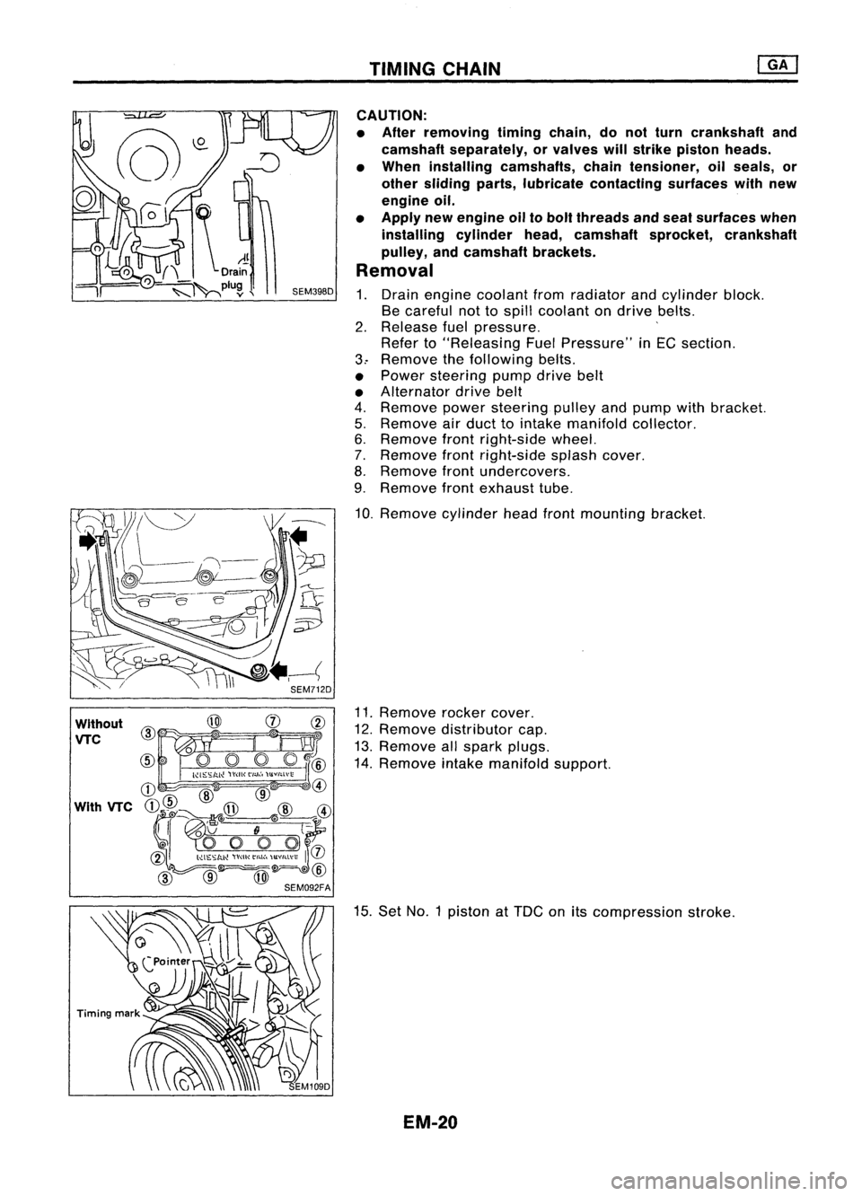
Removal
1. Drain engine coolant fromradiator andcylinder block.
Be careful nottospill coolant ondrive belts.
2. Release fuelpressure. '
Refer to"Releasing FuelPressure" inEG section.
3.. Remove thefollowing belts.
• Power steering pumpdrivebelt
• Alternator drivebelt
4. Remove powersteering pulleyandpump withbracket.
5. Remove airduct tointake manifold collector.
6. Remove frontright-side wheel.
7. Remove frontright-side splashcover.
8. Remove frontundercovers.
9. Remove frontexhaust tube.
10. Remove cylinderheadfrontmounting bracket.
11. Remove rockercover.
12. Remove distributor cap.
13. Remove allspark plugs.
14. Remove intakemanifold support.
15. Set NO.1 piston at
TOG
onitscompression stroke.
EM-20