Page 1209 of 1701
OILSEAL REPLACEMENT
KV10l07902
VALVE
OilSEAL
1. Remove rockercover.
2. Remove camshaft.
3. Remove valvespring. Referto"CYLINDER HEAD".
4. Remove valveoilseal withasuitable tool.
Piston concerned shouldbeset atTOC toprevent valvefrom
falling.
5. Apply engine oiltonew valve oilseal andinstall itwith Tool.
SEM136D
10.5
mm
(0.413 In)
SEM137D
FRONTOilSEAL
1. Remove thefollowing parts:
• Engine undercover
• Right-side splashcover
• Alternator andpower steering drivebelts
• Crankshaft pulley
2. Remove frontoilseal from front cover.
Be careful nottodamage oilseal portion.
• Install newoilseal inthe direction shown.
Engine /',
inside
Y
~
Engine
Youtside
Oil seal lip Dust
seal
lip
SEM715A EM-30
Page 1224 of 1701

ENGINEREMOVAL
WARNING:
a. Situate vehicle onaflat and solid surface.
b. Place chocks atfront andback ofrear wheels.
c. Donot remove engineuntilexhaust systemhascompletely
cooled off.
Otherwise, youmay burn yourself and/orfiremay break out
in fuel line.
d. For safety during subsequent steps,thetension ofwires
should beslackened againsttheengine.
e. Before disconnecting fuelhose, release fuelpressure from
fuel line.
Refer to"Releasing FuelPressure" inEC section.
f. Besure tohoist engine andtransaxle inasafe manner.
g. For engines notequipped withengine slingers, attach
proper slingers andbolts described inPARTS CATALOG.
CAUTION:
• When liftingengine, besure toclear surrounding parts.
Take special careforaccelerator wirecasing, brakelines
and brake master cylinder.
• Inhoisting theengine, alwaysuseengine slingers inasafe
manner.
• Inremoving driveshaft, becareful nottodamage grease
seal oftransaxle.
Engine cannotberemoved separately fromtransaxle. Remove
engine withtransaxle.
Removal
1. Drain water.
2. Remove hood.
3. Remove battery.
4. Remove reservoir tankandbracket.
5. Remove drivebelts.
6. Remove alternator, compressor andpower steering oil
pump fromengine.
Power steering pumpdoesnotneed tobe disconnected from
power steering tubes.
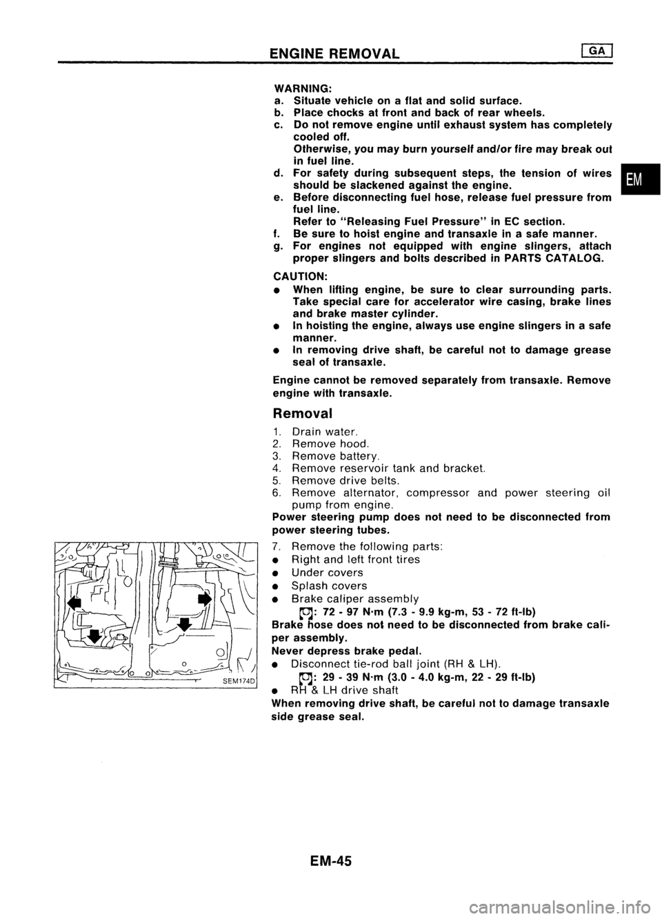
7. Remove thefollowing parts:
• Right andleftfront tires
• Under covers
• Splash covers
• Brake caliper assembly
~: 72-97 N'm (7.3•9.9 kg-m, 53•72 ft-Ib)
Brake hosedoes notneed tobe disconnected frombrake cali-
per assembly.
Never depress brakepedal.
• Disconnect tie-rodballjoint (RH
&
LH).
~: 29-39 N'm (3.0-4.0 kg-m, 22-29 ft-Ib)
• RH
&
LH drive shaft
When removing driveshaft, becareful nottodamage transaxle
side grease seal.
EM-45
•
Page 1240 of 1701
SEC.118-140-230-275
~ :N.m (kg-m, in-Ib)
tc.J :
N'm (kg-m, ft-Ib)
D :Apply
liquidgasket.
(}) Oillevel gauge
@
Alternator adjustingbar
@
Compressor bracket
@
Alternator bracket
OUTER
COMPONENT PARTS
@
Water outlet
@
Drain plug
(J)
Crankcase ventilationoilsepa-
rator
EM-61
tc.J
37•48
(3.8 •4.9, 27.35)
tc.J
40.50 (4.1-5.1, 30-37)
SEM233F
@
Exhaust manifold
@
Heated oxygen sensor
@
Exhaust manifold cover
•
Page 1248 of 1701
TIMINGCHAIN
CAUTION:
• After removing timingchain,donot turn crankshaft and
camshaft separately, orvalves willstrike piston heads.
• When installing rockerarms,camshafts, chaintensioner, oil
seals, orother sliding parts,lubricate contacting surfaces
with newengine oil.
• Apply newengine oiltobolt threads andseat surfaces when•
installing cylinderhead,camshaft sprockets, crankshaft
pulley, andcamshaft brackets.
Removal
1. Release fuelpressure.
Refer to"Releasing FuelPressure" inEC section.
2. Remove engineundercovers.
3. Remove frontRHwheel andengine sidecover.
4. Drain coolant byremoving cylinderblockdrainplugand
radiator draincock.
5. Remove radiator.
6. Remove airduct tointake manifold.
7. Remove drivebeltsandwater pumppulley.
8. Remove alternator andpower steering oilpump.
9. Remove vacuumhoses,fuelhoses, wires,harness, connec-
tors andsoon.
10. Remove allspark plugs.
11. Remove rockercoverandoilseparator.
12. Remove intakemanifold supports.
EM-69
Page 1260 of 1701

Unit:mm(in)
10
(0.39)
n'
Engine front
1+ .,..I
3 (0.12) ~LiqUid
gasket
SEM366D TIMING
CHAIN
Installation (Cont'd)
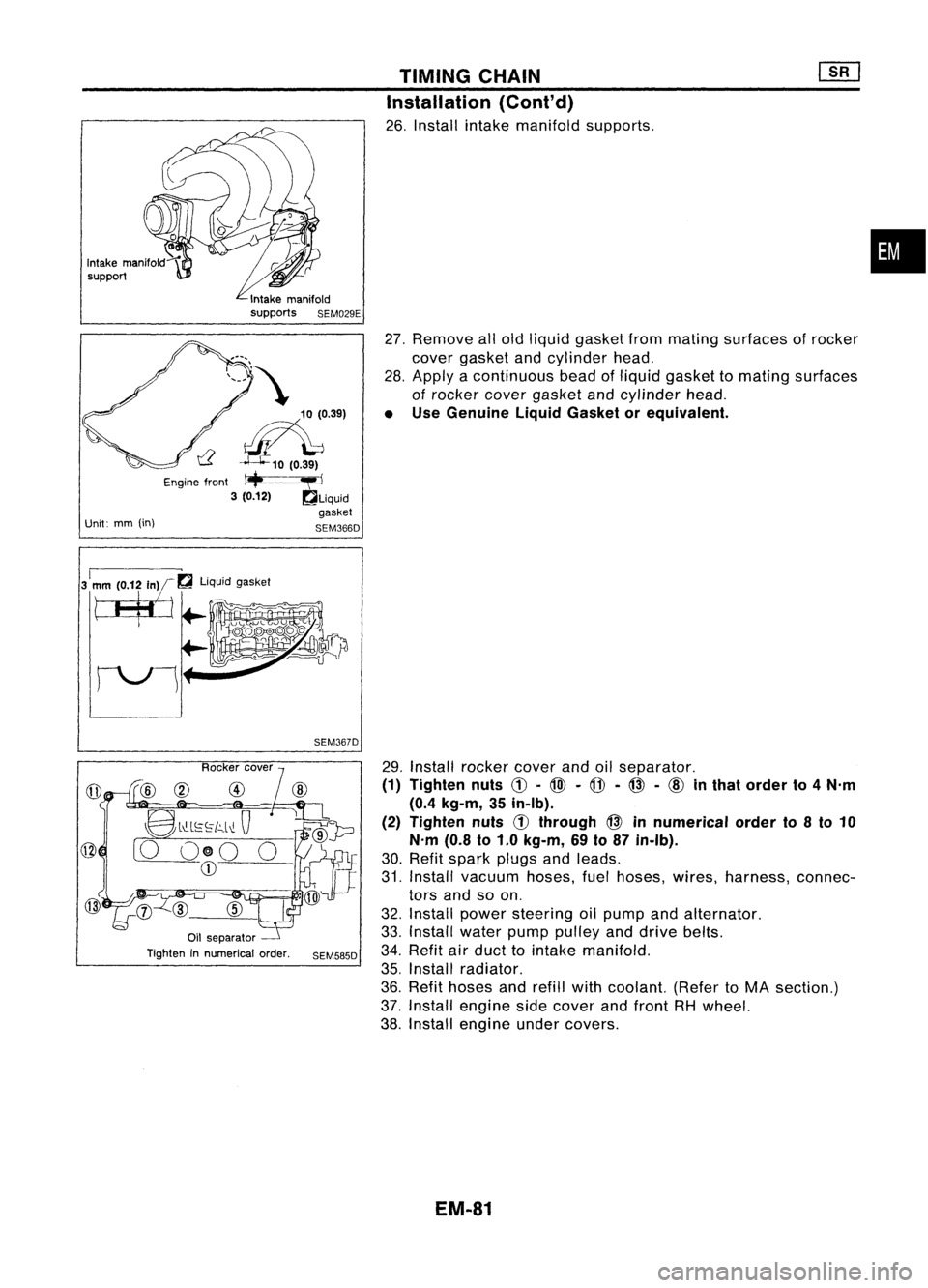
26. Install intakemanifold supports.
27. Remove allold liquid gasket frommating surfaces ofrocker
cover gasket andcylinder head.
28. Apply acontinuous beadofliquid gasket tomating surfaces
of rocker covergasket andcylinder head.
• Use Genuine LiquidGasket orequivalent.
•
3
1
mm (0.12
In)r~
liquidgasket
tJ$j
SEM367D
@
8l"-L~~[c,.l~
Q
[0 O@O 0
CD
Oil separator
Tighten innumerical order.
SEM585D
29.
Install rocker coverandoilseparator.
(1) Tighten nuts
C!J-
@l -
@ -@ -
cID
inthat order to4N'm
(0.4 kg-m, 35in-Ib).
(2) Tighten nuts
d)
through @innumerical orderto8to 10
N'm (0.8to1.0 kg-m, 69to87 in-Ib).
30. Refit spark plugsandleads.
31. Install vacuum hoses,fuelhoses, wires,harness, connec-
tors andsoon.
32. Install power steering oilpump andalternator.
33. Install waterpumppulley anddrive belts.
34. Refit airduct tointake manifold.
35. Install radiator.
36. Refit hoses andrefill withcoolant. (RefertoMA section.)
37. Install engine sidecover andfront RHwheel.
38. Install engine undercovers.
EM-81
Page 1278 of 1701

SEM092DENGINE
REMOVAL
WARNING:
• Situate vehicle onaflat and solid surface.
• Place chocks atfront andback ofrear wheels.
• Donot remove engineuntilexhaust systemhascompletely
cooled off.
Otherwise, youmay burn yourself and/orfiremay break out
in fuel line.
• For safety during subsequent steps,thetension ofwires
should beslackened againsttheengine.
• Before disconnecting fuelhose, release fuelpressure from
fuel line.
Refer to"Releasing FuelPressure" inEC section.
• Besure tohoist engine andtransaxle inasafe manner.
• For engines notequipped withengine slingers, attach
proper slingers andbolts described inPARTS CATALOG.
CAUTION:
• When liftingengine, becareful nottostrike adjacent parts,
especially thefollowing: Accelerator wirecasing, brake
lines, andbrake master cylinder.
• Inhoisting theengine, alwaysuseengine slingers inasafe
manner.
Removal
1. Remove engineundercoverandhood.
2. Drain coolant frombothcylinder block,andradiator.
3. Drain engine oilfrom drain plugofoil pan.
4. Remove vacuumhoses,fuelhoses, wires,harness andcon-
nectors andsoon.
5. Remove exhausttubes,balljoints anddrive shafts.
6. Remove radiatorandfans.
7. Remove drivebelts.
8. Remove alternator, compressor andpower steering oil
pump fromengine.
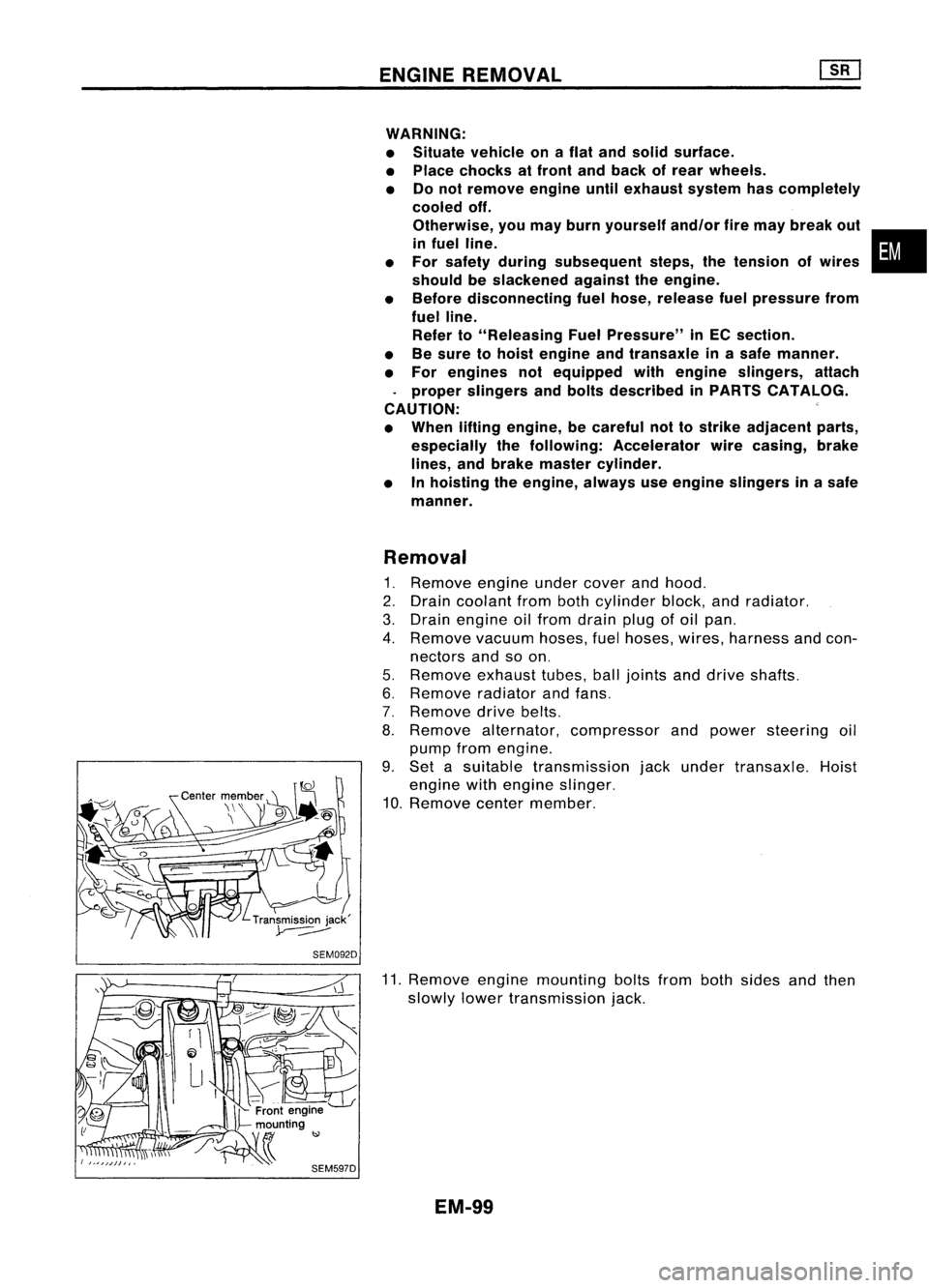
9. Set asuitable transmission jackunder transaxle. Hoist
engine withengine slinger.
10. Remove centermember.
11. Remove enginemounting boltsfrombothsides andthen
slowly lowertransmission jack.
EM-99
•
Page 1293 of 1701
OUTERCOMPONENT PARTS
Left side
SEC. 120.135.140.210.230
l"J
16•21 (1.6 .2.1. 12•
7
<, ~
~
/
7~
~ 16-21 (1.6 •2.1, 12•15)~~""
Ii] :
N.m (kg-m, in-Ib)
~ :N.m (kg-m, fl-Ib)
L
~-@@~
-@
~18•22 (1.8 -2.2, 13.16)
6
/
~~ ~2.75(6.3.7.6,46 -55)
SEM045FA
CD
Beltcover upper
@
Water pumppulley
@
Beltcover lower
@
Crankshaft pulley
@
Alternator
@
Alternator bracket
EM-114
(J)
Exhaust manifold
@
Gasket
@
Intake manifold
Page 1503 of 1701

ENGINEMAINTENANCE
EXCEPT FORGA14DE ENGINE Checking
DriveBelts
•
~ 16-21
(1.6 •2.1, 12•15)
Alternator
SMA786CA
Without
airconditioner
Crankshaft
pUlley
~
25.5 -32.4 (2.60 -3.30, 18.8-23.9)
Compressor
Power steering
pump (or Idler pulley)
With
airconditioner
Idler
pulley
Crankshaft
pulley
Power
steering pump
(or Idler pulley)
~.
~6.3 -8.3 (0.64 -0.85, 55.6-73.8)
~ :Checking point
A :
N.m (kg-m, ft-lb)
III :
N.m (kg-m, in-Ib)
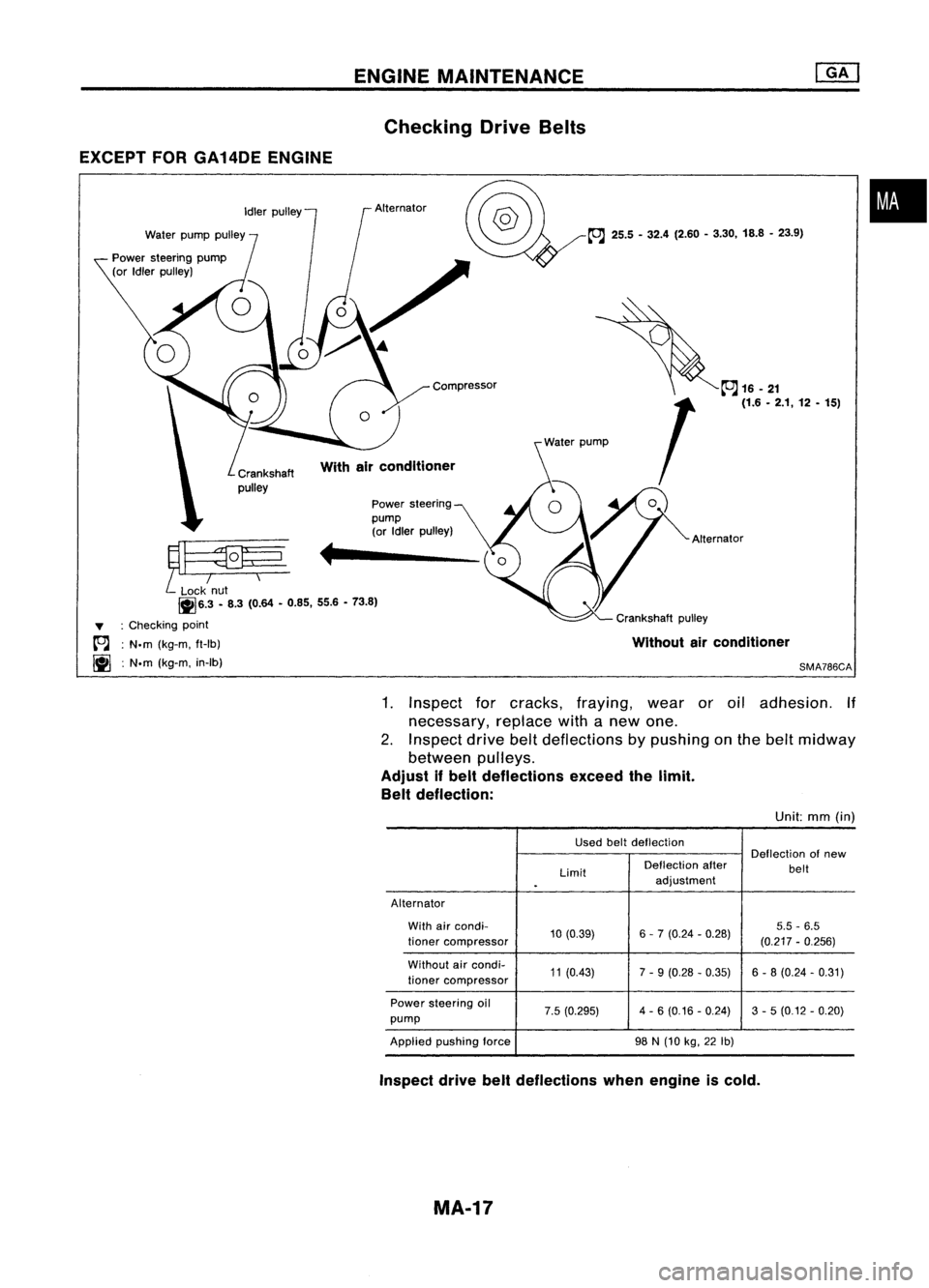
1.Inspect forcracks, fraying, wearoroil adhesion. If
necessary, replacewithanew one.
2. Inspect drivebeltdeflections bypushing onthe belt midway
between pulleys.
Adjust ifbelt deflections exceedthelimit.
Belt deflection:
Unit:mm(in)
Used beltdeflection
Deflectionofnew
Limit Deflection
after
belt
.
adjustment
Alternator With aircondi-
10(0.39) 6-7 (0.24 -0.28) 5.5
-6.5
lioner compressor
(0.217-0.256)
Without aircondi-
11(0.43) 7-9 (0.28 -0.35) 6-8 (0.24 -0.31)
lioner compressor
Power steering oil
7.5(0.295) 4
-6 (0.16 -0.24) 3-5 (0.12 -0.20)
pump
Applied pushing force
98
N
(10
kg,
22
Ib)
Inspect drivebeltdeflections whenengine iscold.
MA-17