1995 NISSAN ALMERA N15 fuse chart
[x] Cancel search: fuse chartPage 325 of 1701

TROUBLEDIAGNOSES
Self-diagnosis (ForEurope) (Cont'd)
MALFUNCTION CODE/SYMPTOM CHART
Code No.
Malfunctioningpart Diagnostic
procedure
(No. ofwarning lampflashes)
45
Actuator
frontleftoutlet solenoid valve
3
46
Actuator
frontleftinlet solenoid valve
3
41
Actuator
frontrightoutlet solenoid valve
3
42
Actuator
frontrightinletsolenoid valve
3
51
Actuator
rearright outlet solenoid valve
3
52
Actuatorrearright inletsolenoid valve
3
55
Actuator
rearleftoutlet solenoid valve
3
56
Actuator
rearleftinlet solenoid valve
3
25
Frontleftsensor (open-circuit)
4
26
Front
leftsensor (short-circuit)
4
21
Frontrightsensor (open-circuit)
4
22
Front
rightsensor (short-circuit)
4
35
Rearleftsensor (open-circuit)
4
36
Rear
leftsensor (short-circuit)
4
31
Rearrightsensor (open-circuit)
4
32
Rearrightsensor (short-circuit)
4
18
Sensorrotor
4
61
Actuatormotorormotor relay
5
63
Solenoidvalverelay
6
57
Powersupply (Lowvoltage)
7
71
Controlunit
8
Control unitpower supply circuit
Warning lampstays onwhen igni-Warning
lampbulbcircuit
tion switch isturned on Control
unitorcontrol unitconnector
2
Solenoid valverelaystuck
Power supply forsolenoid valverelaycoil
Warning lampstays on,during
Controlunit
-
self-diagnosis
Warning lampdoesnotcome onFuse, warning lampbulborwarning lampcircuit
1
when ignition switchisturned onControl unit
Warning lampdoes notcome on
Control unit
during self-diagnosis
-
Pedal vibration andnoise
-
9
Long stopping distance
-
10
Unexpected pedalaction
-
11
ABS does notwork
-
12
ABS works frequently
-
13
BR-55
•
Page 373 of 1701

ELECTRICALSYSTEM
SECTION
EL
When youread wiring diagrams:
• Read GIsection, "HOWTOREAD WIRING DIAGRAMS".
When youperform troublediagnos.es, readGIsection, "HOWTOFOllOW FLOWCHART
IN TROUBLE DIAGNOSES" and"HOW TOPERFORM EFFICIENT DIAGNOSIS FORAN
ELECTRICAL INCIDENT".
CONTENTS
PRECAUTIONS 4
Supplemental RestraintSystem(SRS)"AIR
BAG" (DualAirBag System) 4
Supplemental RestraintSystem(SRS)"AIR
BAG" (Single AirBag System) 4
HARNESS CONNECTOR 5
Description 5
STANDARDIZED RELAy 6
Description 6
POWER SUPPLY ROUTING 8
Schematic 8
Wiring Diagram -POWER - 10
Fuse 19
Fusible Link 19
Circuit Breaker 19
GROUND DISTRIBUTION 20
BATTERy 25
How toHandle Battery 25
Battery TestandCharging Chart.. 28
Service DataandSpecifications (SOS) 32
STARTING SySTEM
33
Wiring Diagram -START - 33
Trouble Diagnoses 35
Construction 36
Removal andInstallation .45
Magnetic SwitchCheck .46
Pinion/Clutch Check 46
Brush Check 46
Yoke Check 47
Armature Check 48
Assembly .49
Service DataandSpecifications (SDS) 50
CHARGING SYSTEM 52
Wiring Diagram -CHARGE - 52
Trouble Diagnoses 54Construction
55
Removal andInstallation 57
Disassembly 57
Rotor Check 57
Brush Check 58
Stator Check 58
Diode Check 59
Assembly 60
Service DataandSpecifications (SDS) 61
COMBINATION SWITCH 62
Combination Switch/Check 62
Replacement 64
HEADLAMP -Without Daytime lightSystem -65
Wiring Diagram -H/LAMP - 65
Trouble Diagnoses 67
HEADLAMP -Daytime lightSystem - 68
Operation (Daytimelightsystem) 68
System Description 69
Schematic 70
Wiring Diagram -DTRL - 71
Trouble Diagnoses (DaytimeLight) 74
HEADLAMP 75
Bulb Replacement... 75•
Aiming Adjustment. 75
HEADLAMP -Headlamp Aiming
Control- 77
Wiring Diagram -AIM - 77
Description 81
EXTERIOR LAMP 82
Clearance, LicenseandTail Lamps/Schematic 82
Clearance, LicenseandTail Lamps/Wiring
Diagram -TAILIL - 83
Stop Lamp/Wiring Diagram-STOP/L - 92
Back-up Lamp/Wiring Diagram-BACK/L -94
Front FogLamp/Wiring Diagram-F/FOG -96
Front FogLamp BulbReplacement 101
Page 375 of 1701
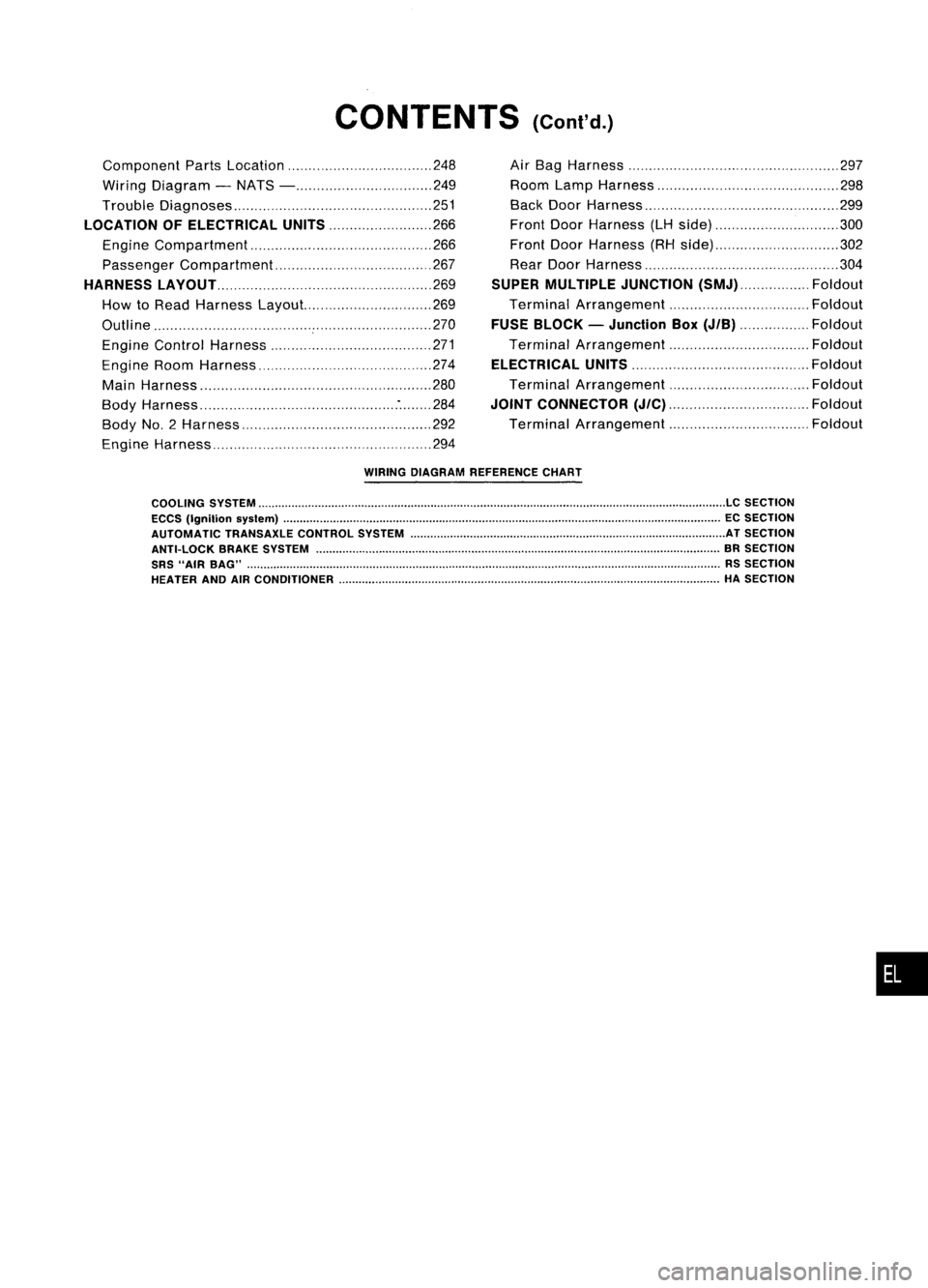
CONTENTS(Cont'd.)
Component PartsLocation 248
Wiring Diagram -NATS - 249
Trouble Diagnoses 251
LOCATION OFELECTRICAL UNITS
266
Engine Compartment 266
Passenger Compartment 267
HARNESS LAyOUT
269
How toRead Harness Layout... 269
Outline 270
Engine Control Harness 271
Engine RoomHarness 274
Main Harness '" 280
Body Harness :284
Body No.2 Harness 292
Engine Harness 294Air
Bag Harness 297
Room LampHarness 298
Back DoorHarness 299
Front DoorHarness (LHside) 300
Front DoorHarness (RHside) 302
Rear Door Harness 304
SUPER MULTIPLE JUNCTION
(SMJ) Foldout
Terminal Arrangement Foldout
FUSE BLOCK -Junction Box
(JIB)
Foldout
Terminal Arrangement Foldout
ELECTRICAL UNITS
Foldout
Terminal Arrangement Foldout
JOINT CONNECTOR
(J/C)
Foldout
Terminal Arrangement Foldout
WIRING DIAGRAM REFERENCE CHART
COOLING SYSTEM
LC
SECTION
ECCS (Ignition syslem) ECSECTION
AUTOMATIC TRANSAXLECONTROLSYSTEM ATSECTION
ANTI-LOCK BRAKESYSTEM BRSECTION
SRS "AIR BAG" RSSECTION
HEATER ANDAIRCONDITIONER HASECTION
•
Page 628 of 1701

NATS(Nissan Anti-Theft System)
Trouble Diagnoses (Cont'd)
SYMPTOM
SYSTEM REFERENCEPART Displayed"SELF- DIAGNOSTIC
PROCE-
(Malfunctioning NO.OFILLUSTRA-
•Blinking ofMIL*. •
Blinking ofMIL *.
DIAGRESULTS" on DURE
part ormode)
TIONONNEXT PAGE
•Engine willstart. •
Hard tostart
CONSULTscreen. (Reference
page)
engine.
System initialisation
has notyetbeen
F X
10
DISCORD, IMM- PROCEDURE 6
completed. ECM(EL-263)
ECM F X
Noise interference in
XMINGLE
NOISE PROCEDURE
7
communication line (EL-264)
Engine trouble data
DON'TERASE
and NATS trouble
BEFORECHECKING WORK
FLOW
data have been X
X
(EL-251)
detected inECM ENG
DIAG
SYMPTOM MATRIXCHART2
(Non self-diagnosis relateditem)
X:Possibility item
SYSTEM SYMPTOM
DIAGNOSTIC
PROCE-
(Malfunctioning partormode) DURE
NATS security indodoes notlight up.
(Referencepage)
NATS security indo
Open circuit between FuseandNATS IMMU
PROCEDURE8
X (EL-264)
Continuation ofinitialisation mode
NATS IMMU
DIAGNOSTIC SYSTEMDIAGRAM
NATS antenna amp.
PART
0 Key10chip (PART E5)
i-------
L---
--j)))
:
.
, ,
I~ .'
(((
NATS ignition
key
PART
E1,E2,E3, E4 IGN
PART C2~ +1./PART C1(MIL)
PART C4
ECM
..
........
................
:'
.......
PART F
D
IGN
EL-256
CONSULT
SEL466U
Page 1116 of 1701
TROUBLEDIAGNOSES ~
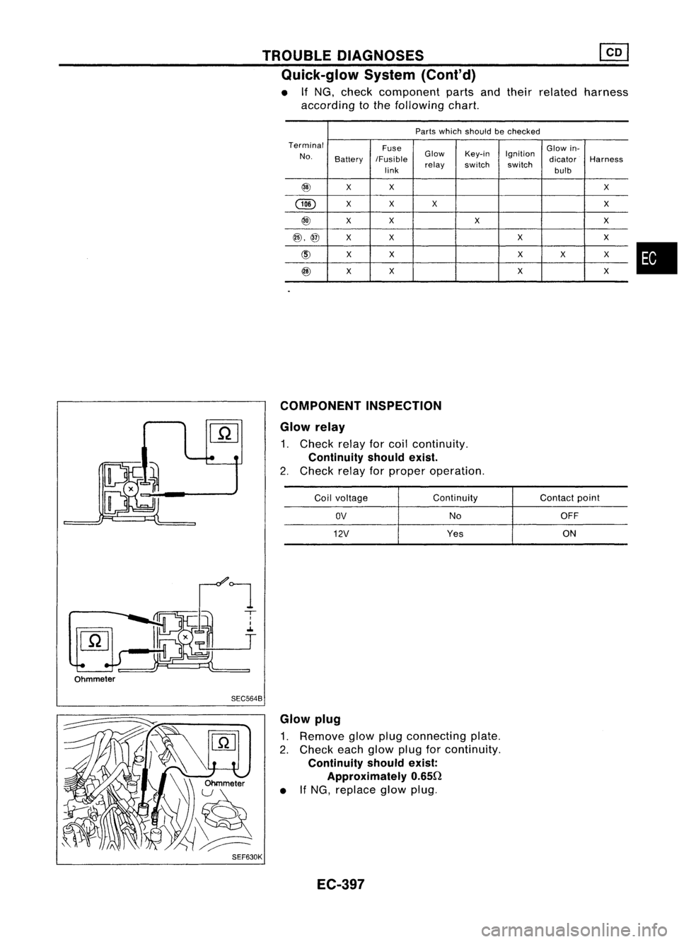
Quick-glow System(Cont'd)
• If
NG.
check component partsandtheir related harness
according tothe following chart.
Parts which should bechecked
Terminal Fuse Glowin-
No. Battery IFusible Glow
Key-in Ignition
dicatorHarness
link relay
switch switch
bulb
@
XX
X
@
X
X X X
@
XX
X X
@,@
XX XX
@
XX X
X X
@
X
X XX
COMPONENT INSPECTION
Glow relay
1. Check relayforcoil continuity.
Continuity shouldexist.
2. Check relayforproper operation.
Coil voltage Continuity
Contactpoint
OV
NoOFF
12V
Yes ON
•
Ohmmeter SEC5648
SEF630K Glow
plug
1. Remove glowplugconnecting plate.
2. Check eachglow plugforcontinuity.
Continuity shouldexist:
Approximately 0.650
• IfNG, replace glowplug.
EC-397
Page 1366 of 1701
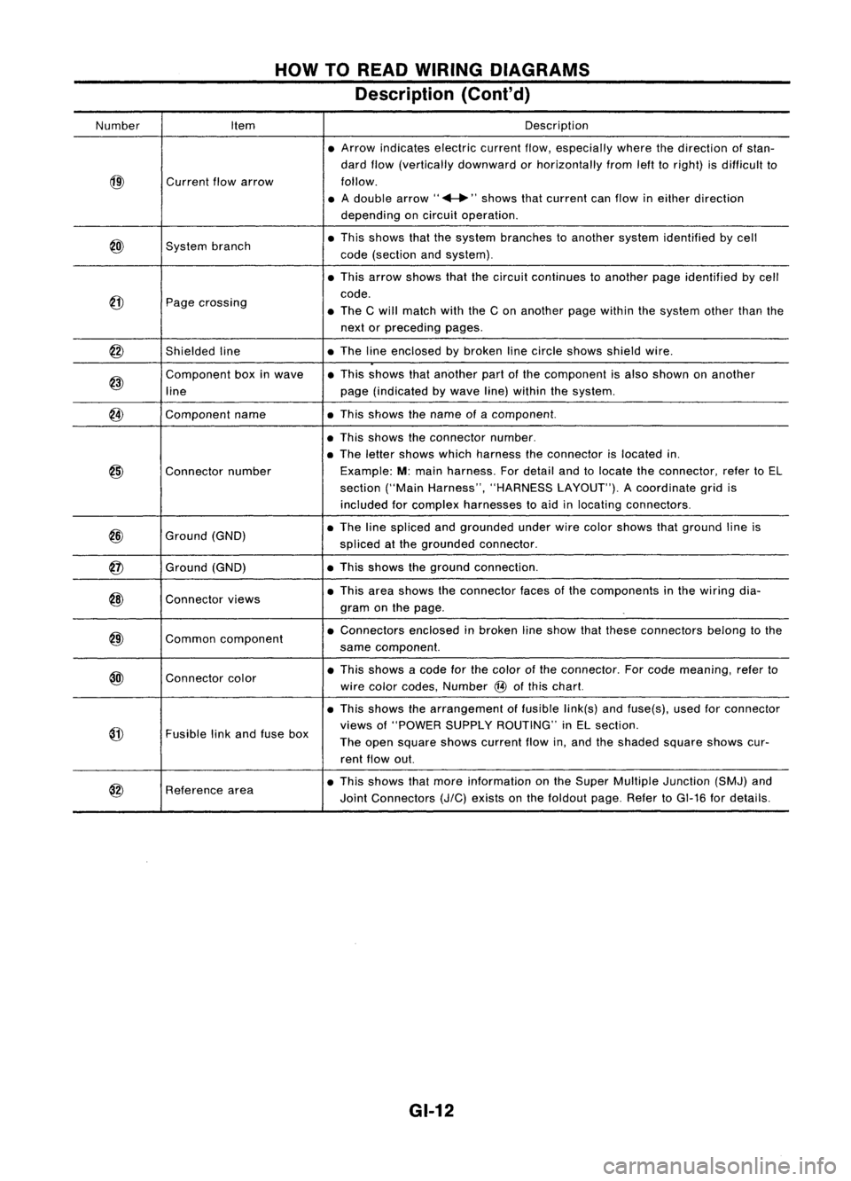
HOWTOREAD WIRING DIAGRAMS
Description (Cont'd)
Number Item Description
• Arrow indicates electriccurrentflow,especially wherethedirection ofstan-
dard flow(vertically downward orhorizontally fromlefttoright) isdifficult to
@)
Current
flowarrow follow.
• Adouble arrow" ...."shows thatcurrent canflow ineither direction
depending oncircuit operation .
@)
System
branch •
This shows thatthesystem branches toanother systemidentified bycell
code (section andsystem) .
• This arrow shows thatthecircuit continues toanother pageidentified bycell
@
code.
Page crossing
•The Cwill match withtheCon another pagewithin thesystem otherthanthe
next orpreceding pages.
@
Shieldedline •
The lineenclosed bybroken linecircle shows shieldwire.
@)
Component
boxinwave •
This shows thatanother partofthe component isalso shown onanother
line page
(indicated bywave line)within thesystem.
@
Component
name •This shows thename ofacomponent.
• This shows theconnector number.
• The letter shows whichharness theconnector islocated in.
@)
Connector
number Example:
M:main harness. Fordetail andtolocate theconnector, refertoEL
section ("MainHarness", "HARNESS LAYOUT").Acoordinate gridis
included forcomplex harnesses toaid inlocating connectors .
@
Ground
(GND) •
The linespliced andgrounded underwirecolor shows thatground lineis
spliced atthe grounded connector.
@
Ground
(GND) •
This shows theground connection.
@)
Connector
views •
This area shows theconnector facesofthe components inthe wiring dia-
gram onthe page .
@)
Common
component •
Connectors enclosedinbroken lineshow thatthese connectors belongtothe
same component.
@l
Connector
color •
This shows acode forthe color ofthe connector. Forcode meaning, referto
wire color codes, Number
@
ofthis chart.
• This shows thearrangement offusible link(s)andfuse(s), usedforconnector
@
views
of"POWER SUPPLYROUTING" inEL section.
Fusible linkand fuse box
Theopen square showscurrent flowin,and theshaded squareshowscur-
rent flow out.
@
Reference
area •
This shows thatmore information onthe Super Multiple Junction (SMJ)and
Joint Connectors
(J/C)
exists onthe foldout page.RefertoGI-16 fordetails.
GI-12
Page 1382 of 1701
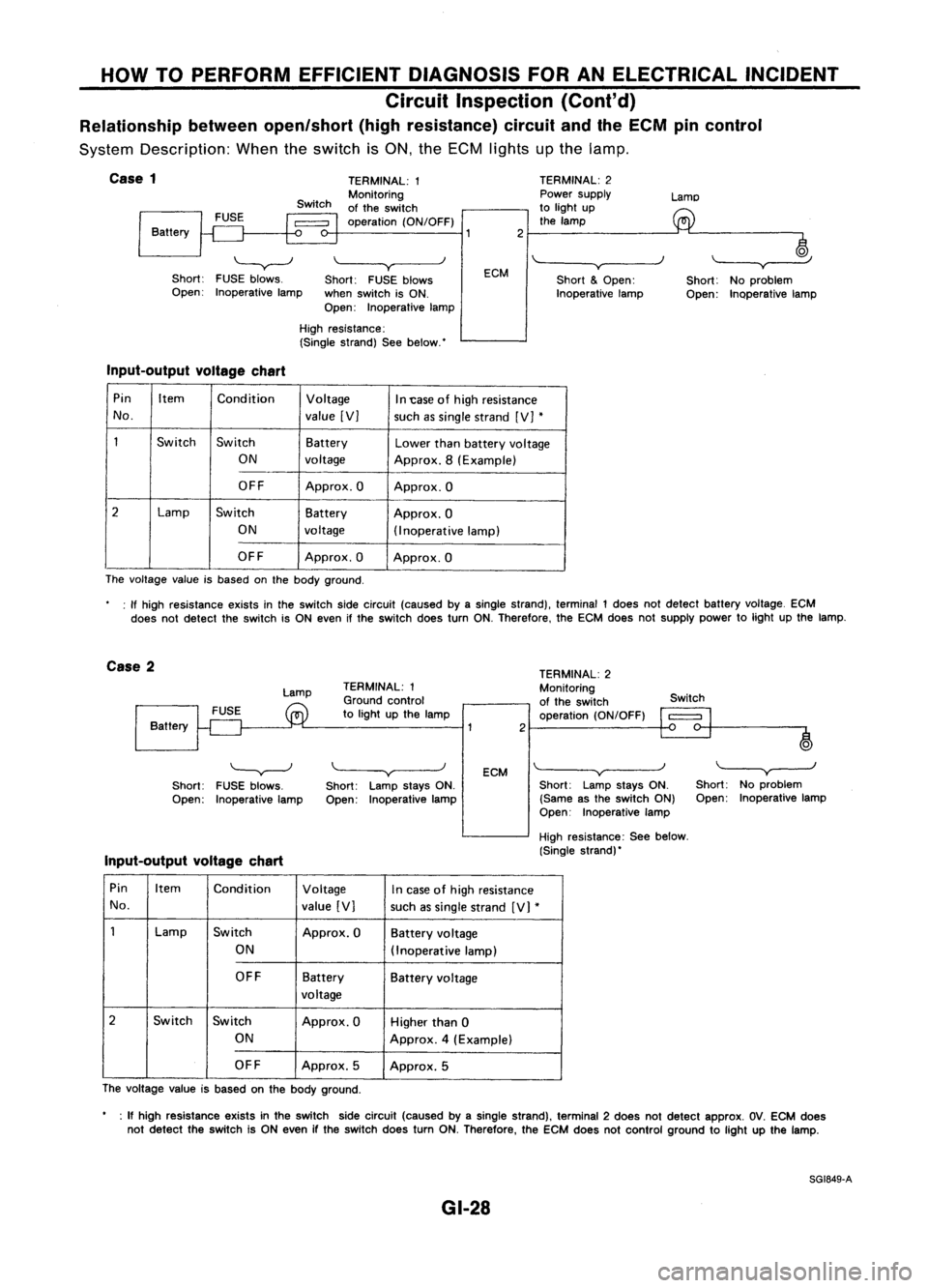
HOWTOPERFORM EFFICIENT DIAGNOSIS FORANELECTRICAL INCIDENT
Circuit Inspection (Cont'd)
Relationship betweenopen/short (highresistance) circuitandtheECM pincontrol
System Description: Whentheswitch isON, theECM lights upthe lamp.
j
Case
1
Battery
'-----v--J
Short: FUSEblows.
Open: Inoperative lamp TERMINAL:
1
Monitoring
of the switch
operation (ON/OFF)
\~--~y
Short: FUSEblows
when switch isON.
Open: Inoperative lampECM
2
TERMINAL:
2
Power supply
to light up
the lamp
'"-----v~----)
Short
&
Open:
Inoperative lampLamo
~
Short: Noproblem
Open: Inoperative lamp
High resistance:
(Single strand) Seebelow.'
Input-output voltagechart
Pin Item
Condition Voltage
In1:ase ofhigh resistance
No. value[V]
suchassingle strand [V]
*
1
Switch
Switch Battery
Lowerthanbattery voltage
ON voltage Approx.8(Example)
OFF Approx.O Approx.O
2
Lamp
Switch Battery
Approx.O
ON voltage
(Inoperativelamp)
OFF Approx.O Approx.O
The voltage valueisbased onthe body ground.
: If high resistance existsinthe switch sidecircuit (caused byasingle strand), terminal 1does notdetect battery voltage. ECM
does notdetect theswitch isON even ifthe switch doesturnON.Therefore. theECM does notsupply powertolight upthe lamp.
Case 2
Lamp
Battery TERMINAL:
1
Ground control
to light upthe lamp
2TERMINAL:
2
Monitoring
of the switch
operation (ON/OFF) Switch
o
)
'---v---J
Short: FUSEblows.
Open: Inoperative lamp
Input-output voltagechart
\.----v
Short: LampstaysON.
Open: Inoperative lamp
ECM
\~--~v~--_.J
Short: LampstaysON.
(Same asthe switch ON)
Open: Inoperative lamp
High resistance: Seebelow.
(Single strand)'
"---y-----.J
Short: Noproblem
Open: Inoperative lamp
Pin Item Condition Voltage
Incase ofhigh resistance
No. value[V]
suchassingle strand [V]
*
1
Lamp
Switch
Approx.OBatteryvoltage
ON (Inoperat ivelamp)
OFF Battery
Batteryvoltage
voltage
2
Switch Switch Approx.OHigherthan0
ON Approx.4(Example)
OFF Approx.5
Approx.5
The voltage valueisbased onthe body ground.
• :If high resis1ance existsinthe switch sidecircuit (caused byasingle strand), terminal 2does notdetect approx. OV.ECM does
not detect theswitch isON even ifthe switch doesturnON.Therefore, theECM does notcontrol ground tolight upthe lamp.
SG1849-A
GI-28
Page 1385 of 1701
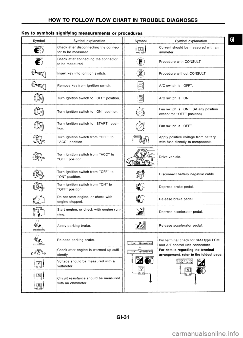
HOWTOFOLLOW FLOWCHART INTROUBLE DIAGNOSES
Key tosymbols signifying measurements orprocedures
Symbol Symbolexplanation
SymbolSymbolexplanation
DISCONNECT
Checkafterdisconnecting theconnec-
~
Current
shouldbemeasured withan
~8
tor
tobe measured.
ammeter.
CONNECT
Checkafterconnecting theconnector
00
E)
tobe measured. Procedure
withCONSULT
(lr~~
Insert
keyinto ignition switCh.
@
Procedure
withoutCONSULT
(lr ..~
Remove
keyfrom ignition switch.
~AIC
switch is"OFF".
~
Turn
ignition switchto"OFF" position.
~AIC
switch is"ON".
~
"
Fanswitch is"ON". (Atany position
Turn ignition switchto"ON" position.
@:;
exceptfor"OFF" position)
~ "
Turn ignition switchto"START" posi-
@'~
Fan
switch is"OFF".
tion.
~~
Turn
ignition switchfrom"OFF" to
~
Apply
positive voltagefrombattery
"ACC" position.
BA;
withfuse directly tocomponents.
~~r
Turn
ignition switchfrom"ACC" to
m-
~'~:
Drive
vehicle.
"OFF" position.
,.-=.
L
@J~ ..
~(e.-
OON
Turn
ignition switchfrom"OFF" to
~~
Disconnect
batterynegative cable.
"ON" position.
BAi
~F
Turn
ignition switchfrom"ON" to
~
Depress
brakepedal.
"OFF" position.
~
Do
not start engine, orcheck with
~
Release
brakepedal.
engine stopped.
ID
Start
engine, orcheck withengine run-
~
ning. Depress
accelerator pedal.
.
.
~
Apply
parking brake.
i!J
Release
accelerator pedal.
..
~
Release
parkingbrake.
~
Pin
terminal checkforSMJ typeECM
and
AIT
control unitconnectors
or
Cff~H
Check
afterengine iswarmed upsuffi-
~ For
details regarding theterminal
ciently.
B
arrangement,refertothe foldout page.
~io
~
Voltage
shouldbemeasured witha
lltlllliR~
t~~~18
voltmeter.
[YJ
lJ9j
.
-
Circuit resistance shouldbemeasured
lfJJ
with
anohmmeter.
~
GI-31
•