1995 NISSAN ALMERA N15 wheel size
[x] Cancel search: wheel sizePage 345 of 1701
Note
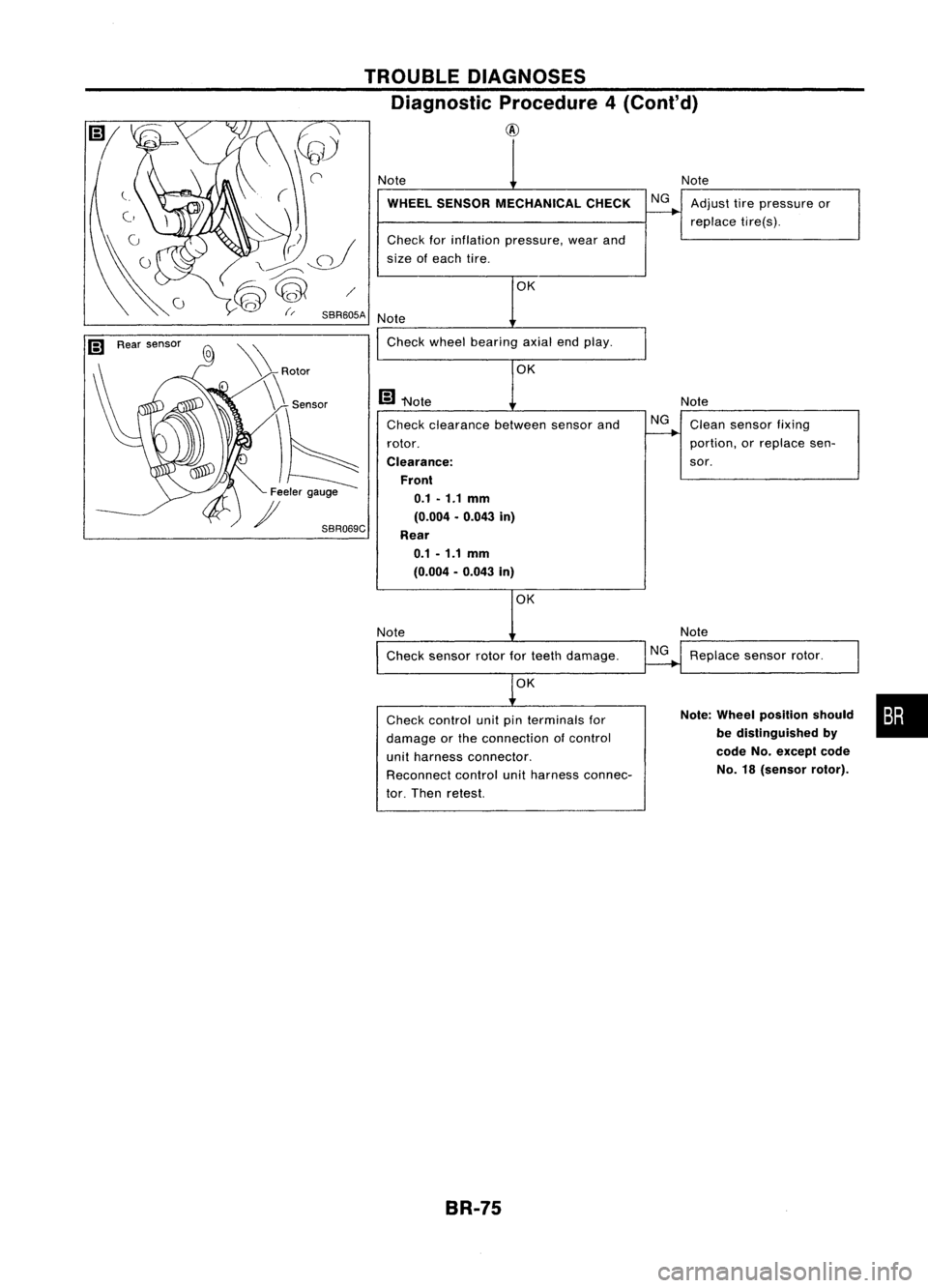
Note Clean sensor fixing
portion, orreplace sen-
sor.
NG
OK
OK
Check clearance betweensensorand
rotor.
Clearance: Front0.1 -1.1
mm
(0.004 .0.043 in)
Rear 0.1 -1.1 mm
(0.004 -0.043 in)
WHEEL
SENSOR MECHANICAL CHECK
NGAdjust tirepressure or
replace tire(s).
Check forinflation pressure, wearand
size ofeach tire.
Note
Note Check wheelbearing axialendplay.
m
"Note
TROUBLE
DIAGNOSES
Diagnostic Procedure4(Conl'd)
@
SBR069C
\
\ Rotor
\\ Sensor
)6
Feeler gauge
)I
OK
Note Check sensor rotorforteeth damage.
NG
Note
Replace sensorrotor.
OK
Check control unitpinterminals for
damage orthe connection ofcontrol
unit harness connector.
Reconnect controlunitharness connec-
tor. Then retest.
Note:
Wheel position should •••
be distinguished by
code
No.except code
No. 18(sensor rotor).
BR-75
Page 1341 of 1701
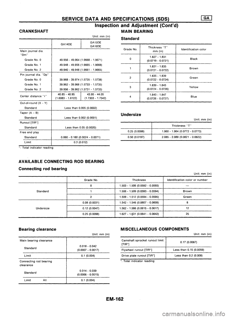
CRANKSHAFT SERVICE
DATAANDSPECIFICATIONS (SOS)
Inspection andAdjustment (Cont'd)
MAIN BEARING
Grade No. Thickness
"T"
Identificationcolor
mm (in)
0 1.827
-1.831
Black
(0.0719 -0.0721)
1 1.831
-1.835
Brown
(0.0721 -0.0722)
2 1.835
-1.839
Green
(0.0722 -0.0724)
3 1.839
-1.843
Yellow
(0.0724 -0.0726)
4 1.843
-1.847
Blue
(0.0726 -0.0727)
Unit:
mm(in)
GA14DE
I
GA15DE
GA16DE
Main journal dia.
"Dm"
Grade No.0 49.956-49.964 (1.9668 -1.9671)
Grade NO.1 49.948-49.956 (1.9665 -1.9668)
Grade NO.2
49.940-49.948 (1.9661 -1.9665)
Pin journal dia."Dp"
Grade No.0 39.968-39.974 (1.5735 -1.5738)
Grade NO.1
39.962-39.968 (1.5733 -1.5735)
Grade No.2 39.956-39.962 (1.5731 -1.5733)
Center distance "r" 40.85
-40.95
I
43.95
-44.05
(1.6083 -1.6122) (1.7303-1.7342)
Out-ot-round (X-Y)
Standard Lessthan0.005 (0.0002)
Taper (A-B)
Standard Lessthan0.002 (0.0001)
Runout [TIW]
Standard Lessthan0.05(0.0020)
Free endplay
Standard 0.060-0.180 (0.0024 -0.0071)
Limit 0.3(0.012)
': Total indicator reading Standard
Undersize 0.25(0.0098)
0.50 (0.0197) Unit:
mm(in)
Thickness "T"
1.960 -1.964 (0.0772 -0.0773)
2.085 -2.089 (0.0821 -0.0822)
AVAILABLE CONNECTING RODBEARING
Connecting rodbearing
Unit:mm(in)
Grade No. Thickness
Identificationcolorornumber
0 1.503
-1.506 (0.0592 -0.0593)
-
Standard 11.506-1.509 (0.0593 -0.0594) Brown
2 1.509
-1.512 (0.0594 -0.0595) Green
0.08 (0.0031) 1.542
-1.546 (0.0607 -0.0609)
8
Undersize 0.12(0.0047) 1.562
-1.566 (0.0615 -0.0617) 12
0.25 (0.0098) 1.627
-1.931 (0.0641 -0.0642) 25
Bearing clearance
Unit:mm(in) MISCELLANEOUS
COMPONENTS
Unit:mm(in)
Main bearing clearance
Standard Limit
Connecting rodbearing
clearance 0.018
-0.042
(0.0007 -0.0017)
0.1 (0.004) Camshaft
sprocketrunoutlimit
[TIW]
Flywheel runout[TIW]
Drive platerunout [T1R']
': Total indicator reading 0.17
(0.0067)
Less than0.15(0.0059)
Less than0.2(0.008)
Standard Limit All 0.014
-0.039
(0.0006 -0.0015)
0.1 (0.004)
EM-162
Page 1349 of 1701
SEM685D
#5
#4 ~
~il hole #3~~ \)
#2 ~~'
#1~~~ ~~
L2 ~~
Engine front~
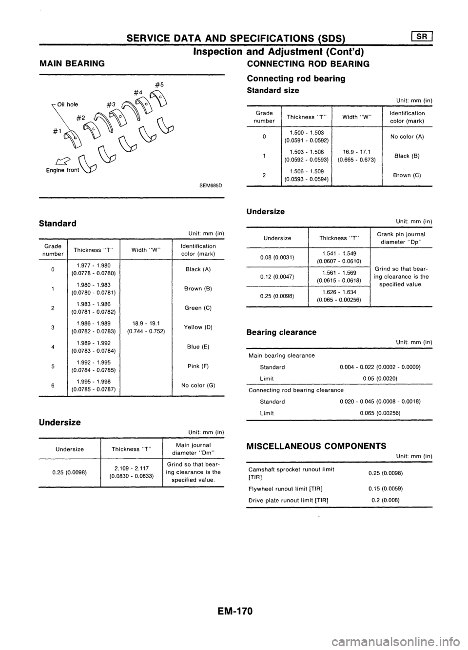
MAIN
BEARING SERVICE
DATAANDSPECIFICATIONS (SOS)
Inspection andAdjustment (Cont'd)
CONNECTING RODBEARING
Connecting rodbearing
Standard size
Unit:mm(in)
Grade Thickness"T"Width"W" Identification
number color(mark)
0 1.500
-1.503
Nocolor (A)
(0.0591 -0.0592)
1 1.503
-1.506 16.9-17.1
Black(B)
(0.0592 -0.0593) (0.665-0.673)
2 1.506
-1.509
Brown(C)
(0.0593 -0.0594)
Undersize
Standard
Unit:
mm(in)
Connecting rodbearing clearance
Undersize
Thickness
"T"
Crank
pinjournal
diameter "Op"
0.08 (0.0031) 1.541
-1.549
(0.0607 -0.0610)
1.561 -1.569
Grind
sothat bear-
0.12 (0.0047)
(0.0615-0.0618)
ing
clearance isthe
specified value.
0.25 (0.0098) 1.626
-1.634
(0.065 -0.00256)
Unit:
mm(in)
Grade Thickness "T"Width"W" Identification
number color
(mark)
0 1.977
-1.980
Black(A)
(0.0778 -0.0780)
1 1.980
-1.983
Brown(B)
(0.0780 -0.0781)
2 1.983
-1.986
Green(C)
(0.0781 -0.0782)
3 1.986-1.989
18.9-19.1
Yellow(D)
(0.0782 -0.0783) (0.744
-0.752)
4 1.989
-1.992
Blue(E)
(0.0783 -0.0784)
5 1.992
-1.995
Pink(F)
(0.0784 -0.0785)
6 1.995
-1.998
Nocolor (G)
(0.0785 -0.Q787)
Undersize
Unit:mm(in)
Bearing
clearance
Main bearing clearance
Standard
Limit
Standard
Limit Unit:
mm(in)
0.004 -0.022 (0.0002 -0.0009)
0.05 (0.0020)
0.020 -0.045 (0.0008 -0.0018)
0.065 (0.00256)
Undersize Thickness
"T" Main
journal
diameter "Om"
MISCELLANEOUS
COMPONENTS
Unit:mm(in)
0.25 (0.0098) 2.109
-2.117
(0.0830 -0.0833)
Grind
sothat bear-
ing clearance isthe
specified value. Camshaft
sprocketrunoutlimit
[TIR]
Flywheel runoutlimit[TIR]
Drive platerunout limit[TIA]
0.25
(0.0098)
0.15 (0.0059)
0.2 (0.008)
EM-170
Page 1354 of 1701
SERVICEOATAAND SPECIFICATIONS (SOS)
Inspection andAdjustment (Cont'd)
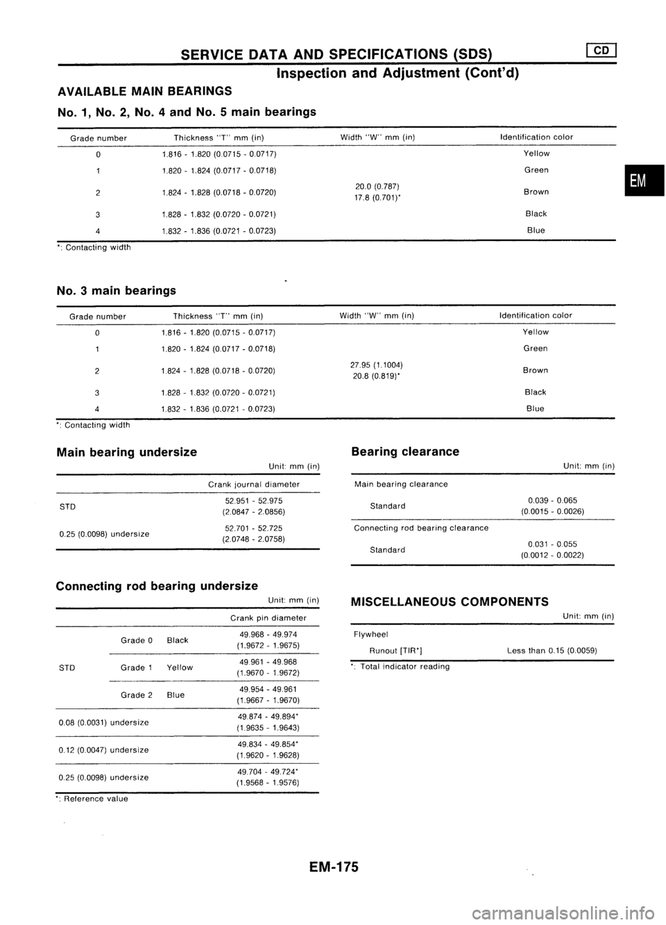
AVAILABLE MAINBEARINGS
No.1, No.2, No.4andNo.5main bearings
Grade number
o
2
3
4
Contacting width Thickness
"T"
mm
(in)
1.816 -1.820 (0.0715 -0.0717)
1.820 -1.824 (0.0717 -0.0718)
1.824 -1.828 (0.0718 -0.0720)
1.828 -1.832 (0.0720 -0.0721)
1.832 -1.836 (0.0721 -0.0723)
Width
"W"
mm
(in)
20.0 (0.787)
17.8 (0.7011'
Identification
color
Yellow
Green
Brown Black Blue
•
No.3 mainbearings
Grade number
o
2
3
4
Contacting width Thickness
"T"
mm
(in)
1.816 -1.820 (0.0715 -0.0717)
1.820 -1.824 (0.0717 -0.0718)
1.824 -1.828 (0.0718 -0.0720)
1828 -1.832 (0.0720 -0.0721)
1.832 -1.836 (0.0721 -0.0723)
Width
"W"
mm
(in)
27.95 (1.1004)
20.8 (0.819)'
Identification
color
Yellow
Green
Brown BlackBlue
Main bearing undersize
Unit:
mm
(in)
Crank journal diameter
Bearing
clearance
Main bearing clearance Unit:
mm
(in)
STD
0.25 (0.0098)
undersize
52951
-52.975
(2.0847 -2.0856)
52.701 -52.725
(2.0748 -2.0758)
Standard
Connecting rodbearing clearance
Standard
0.039
-0.065
(0.0015 -0.0026)
0.031 -0.055
(0.0012 -0.0022)
Connecting rodbearing undersize
Unit:
mm
(in)
Crank pindiameter
MISCELLANEOUS
COMPONENTS
Unit:
mm
(in)
0.25 (0.0098)
undersize
0.08
(0.0031)
undersize
0.12 (0.0047)
undersize
STD
Grade
0Black
Grade 1Yellow
Grade 2Blue
49.968
-49.974
(1.9672 -1.9675)
49961 -49.968
(1.9670 -1.9672)
49.954 -49.961
(1.9667 -1.9670)
49.874 -49.894"
(1.9635 -1.9643)
49.834 -49.854"
(1.9620 -1.9628)
49.704 -49.724"
(1.9568 -1.9576)
Flywheel
Runout
[TIR"]
Total indicator reading Less
than
0.15(0.0059)
": Reference value
EM-175
Page 1393 of 1701
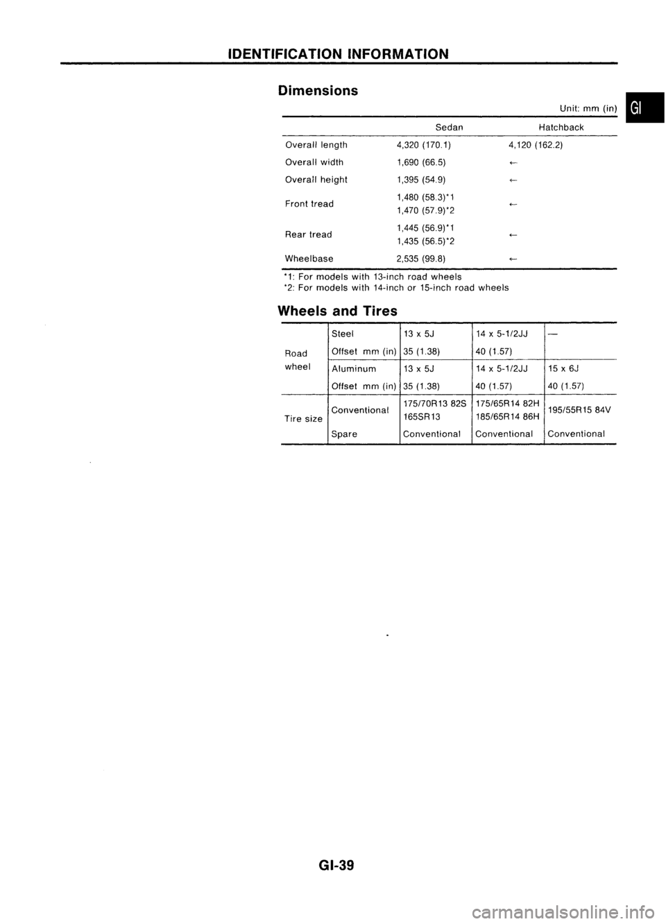
IDENTIFICATIONINFORMATION
Dimensions SedanUnit:
mm(in) •
Hatchback
Overall length
Overall width
Overall height
Front tread
Rear tread
Wheelbase 4,320
(170.1)
1,690 (66.5)
1,395 (54.9)
1,480 (58.3)* 1
1,470 (57.9)*2
1,445 (56.9)*1
1,435 (56.5)*2
2,535 (99.8) 4,120
(162.2)
*1: For models with13-inch roadwheels
*2: For models with14-inch or15-inch roadwheels
Wheels andTires
Steel 13x5J 14x5-1/2JJ
-
Road Offset
mm(in) 35(1.38) 40(1.57)
wheel Aluminum 13x5J 14
x5-1/2JJ 15x6J
Offset mm(in)
35(1.38) 40
(1.57) 40(1.57)
175170R1382S 175/65R1482H
195/55R1584V
Conventional
185/65R1486H
Tire size 165SR13
Spare Conventional
Conventional Conventional
GI-39
Page 1628 of 1701
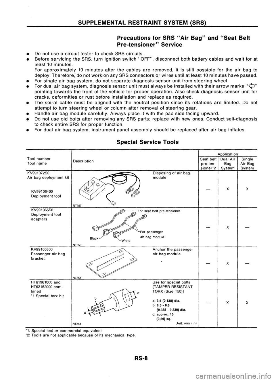
SUPPLEMENTALRESTRAINTSYSTEM(SRS)
Precautions forSRS "AirBag" and"Seat Belt
Pre-tensioner" Service
• Donot use acircuit testertocheck SRScircuits.
• Before servicing theSRS. turnignition switch"OFF", disconnect bothbattery cablesandwait forat
least 10minutes.
For approximately 10minutes afterthecables areremoved, itis still possible forthe airbag to
deploy. Therefore, donot work onany SRS connectors orwires untilatleast 10minutes havepassed.
• For single airbag system, donot separate diagnosis sensorunitfrom steering wheel.
• For dual airbag system. diagnosis sensorunitmust always beinstalled withtheir arrow marks
"Q"
pointing towards thefront ofthe vehicle forproper operation. Alsocheck diagnosis sensorunitfor
cracks. deformities orrust before installation andreplace asrequired.
• The spiral cablemustbealigned withtheneutral position sinceitsrotations arelimited. Donot
attempt toturn steering wheelorcolumn afterremoval ofsteering gear.
• Handle airbag module carefully. Alwaysplaceitwith thepad side facing upward.
• Donot use oldbolts afterremoving anySRS parts; replace withnewones. Conduct self-diagnosis
to check entire SRSforproper function.
• For dual airbag system, instrument panelassembly shouldbereplaced afterairbag inflates.
X
X
Use
forspecial bolts
[TAMPER RESISTANT
TORX (SizeT50))
a:
3.5 (0.138)
dia.
b: 8.5 -8.6
(0.335 •0.339) dia.
c: approx.
10
(0.39) sq.
c
NT354
a
HT61961000
and
HT62152000 com-
bined *1 Special torxbit
Special
Service Tools
Application
Tool number
Description Seat
belt DualAir Single
Tool name
pre-ten-BagAirBag
sioner*2 Sstem Sstem
KV991072So Disposingofair bag
Air bag deployment kit module
KV991 06400
X
X
Deployment tool
KV991065So
Deployment tool
adapters
X
For passenger
air bag module
NT353
KV991 05300 Anchorthepassenger
Passenger airbag
airbag module
bracket
X
NT361
Unit:
mm(in)
*1: Special toolorcommercial equivalent
*2: Tools arenotapplicable becauseofits mechanical type.
RS-8
Page 1632 of 1701
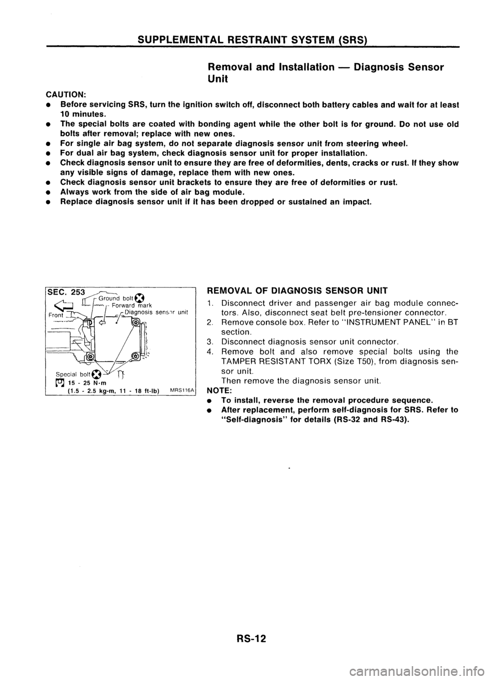
SUPPLEMENTALRESTRAINTSYSTEM(SRS)
Removal andInstallation -Diagnosis Sensor
Unit
CAUTION:
• Before servicing SRS,turntheignition switchoff,disconnect bothbattery cablesandwait foratleast
10 minutes.
• The special boltsarecoated withbonding agentwhiletheother boltisfor ground. Donot use old
bolts afterremoval; replacewithnewones.
• For single airbag system, donot separate diagnosis sensorunitfrom steering wheel.
• For dual airbag system, checkdiagnosis sensorunitforproper installation.
• Check diagnosis sensorunittoensure theyarefree ofdeformities, dents,cracks orrust. Ifthey show
any visible signsofdamage, replacethemwithnewones.
• Check diagnosis sensorunitbrackets toensure theyarefree ofdeformities orrust.
• Always workfromtheside ofair bag module.
• Replace diagnosis sensorunitifithas been dropped orsustained animpact.
SEC. 253~
IT
r
Grou~? bolt~
G ~~ ~
Forward mark
Fr?nt
_--I
d--!
Dia~no:iS senSlrunit
!
Special bOIt~ -
t"'J
15-25 N.m
(1.5 •2.5 kg-m,
11-
18 ft-Ib)
MRS116A REMOVAL
OFDIAGNOSIS SENSORUNIT
1. Disconnect driverandpassenger airbag module connec-
tors. Also, disconnect seatbeltpre-tensioner connector.
2. Remove consolebox.Refer to"INSTRUMENT PANEL"in8T
section.
3. Disconnect diagnosissensorunitconnector.
4. Remove boltandalso remove specialboltsusing the
TAMPER RESISTANT TORX(SizeT50),fromdiagnosis sen-
sor unit.
Then remove thediagnosis sensorunit.
NOTE:
• Toinstall, reverse theremoval procedure sequence.
• After replacement, performself-diagnosis forSRS. Refer to
"Self-diagnosis" fordetails (RS-32andRS-43).
RS-12
Page 1635 of 1701
SUPPLEMENTALRESTRAINTSYSTEM(SRS)
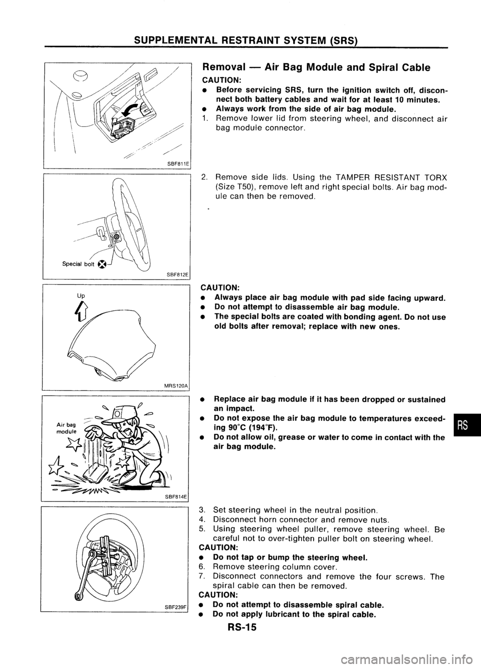
Removal -Air Bag Module andSpiral Cable
CAUTION:
• Before servicing SRS,turntheignition switchoff,discon-
nect both battery cablesandwait foratleast 10minutes.
• Always workfromtheside ofair bag module.
1. Remove lowerlidfrom steering wheel,anddisconnect air
bag module connector.
SBF811E
2.Remove sidelids.Using theTAMPER RESISTANT TORX
(Size T50), remove leftand right special bolts.Airbag mod-
ule can then beremoved.
SBF812E CAUTION:
• Always placeairbag module withpadside facing upward.
• Donot attempt todisassemble airbag module.
• The special boltsarecoated withbonding agent.Donot use
old bolts afterremoval; replacewithnew ones.
MRS120A
Air bag
module
SBF814E•
•
• Replace
airbag module ifithas been dropped orsustained
an impact.
Do not expose theairbag module totemperatures exceed-•
•
ing 90°C (194°F).
Do not allow oil,grease orwater tocome incontact withthe
air bag module.
SBF239F
3.
Set steering wheelinthe neutral position.
4. Disconnect hornconnector andremove nuts.
5. Using steering wheelpuller, remove steering wheel.Be
careful nottoover-tighten pullerboltonsteering wheel.
CAUTION:
• Donot tap orbump thesteering wheel.
6. Remove steering columncover.
7. Disconnect connectorsandremove thefour screws. The
spiral cablecanthen beremoved.
CAUTION:
• Donot attempt todisassemble spiralcable.
• Donot apply lubricant tothe spiral cable.
RS-15