Page 1452 of 1701

TROUBLEDIAGNOSES
INCIDENT Flow
chart
No.
1 Fan fails torotate.
rn
2 Fan
does notrotate at
[2J
1-speed.
3 Fan
does notrotate at
~
2-speed.
4 Fan
does notrotate at
[1J
3-speed.
5 Fan
does notrotate at
[2]
4-speed. Diagnostic
Procedure1
CD
@
@
@
(Go tonext page.)
Check 15A(No.
rn
and
No.
[2J)
fuses atfuse
block.
(Refer to"POWER SUP-
PLY ROUTING" inEL sec-
tion and Wiring Diagram.)
No
Ves
Check
ifblower motorrotates prop-
erly ateach fanspeed.
Conduct checksasper flow chart at
left.
rn
SYMPTOM:
Blowermotordoesnotrotate.
• Perform PRELIMINARY CHECK1before referring tothe fol-
lowing flowchart.
CHECK POWER SUPPLVFOR BLOWER
MOTOR.
Disconnect blowermotorharness con-
nector.
Do approx. 12volts existbetween
blower motorharness terminal No.
CD
and body ground?
LlW
~i5~
Blower motor
connector
@)
m
RHA343F
~ DISCONNECT
IV@a
Blower motor
connector
@)
~ ~Check
circuitcontinuity betweenblower
motor harness terminal No.@and
body ground.
~OK
CHECK BLOWER MOTOR.
(Refer toElectrical Components Inspec-
tion.) (HA-62) Reconnect
blowermotor
harness connector.
LIB
NG
I
Replace blowermotor.
RHA344F
@J
Resistor
connector@
[Qli1JJ
LIB
CHECK
BLOWER MOTORCIRCUIT
BETWEEN BLOWERMOTORAND
RESISTOR
Do approx. 12volts existbetween resis-
tor harness terminal No.
CD
and body
ground?
Ves No
Disconnect blowermotor
and resistor harness con-
nectors.
Note: If the result isNG after checking circuitcontinuity, repairharness orconnec-
tor. Note
Check circuit continuity
between blowermotor
harness terminal No.@
and resistor harness ter-
minal No.
(1).
Continuity shouldexist.
If OK, check harness for
short.
@
(Go tonext page.)
Disconnect
fanswitch harness connec-
tor.
LIB
RHA345F
Blower motor
connector@
~
LIB
Resistor
connector@
61iJ]
RHA346FHA-50
Page 1456 of 1701

TROUBLEDIAGNOSES
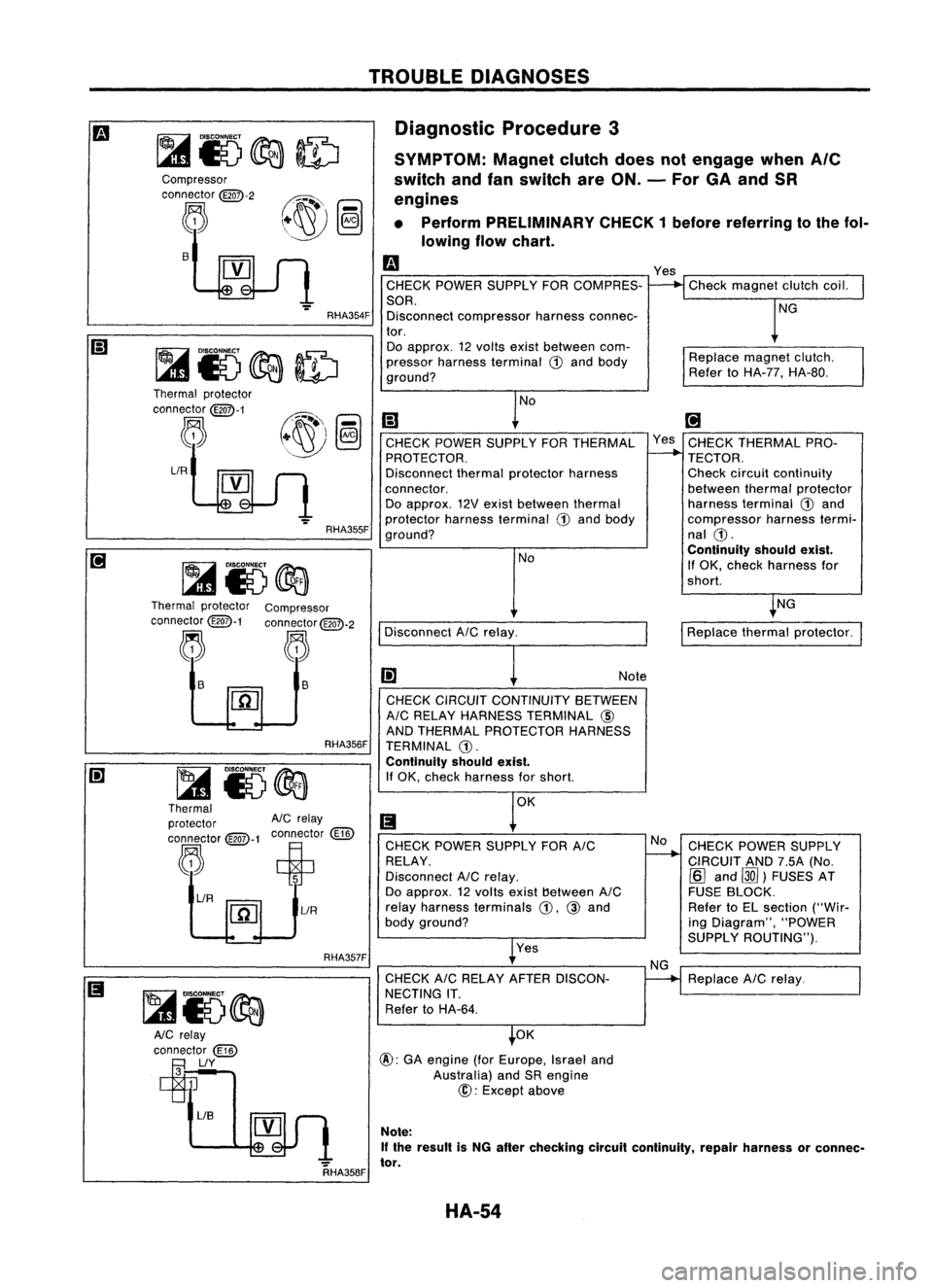
Diagnostic Procedure3
SYMPTOM: Magnetclutchdoesnotengage when
Ale
switch andfanswitch areON. -For GAand SR
engines
• Perform PRELIMINARY CHECK1before referring tothe fol-
lowing flowchart.
Replacemagnetclutch.
Refer toHA-77, HA-80.
Check
magnet clutchcoil.
NG
Yes
m
CHECK POWER SUPPLY FORCOMPRES-
SOR. Disconnect compressor harnessconnec-
tor. Do approx. 12volts existbetween com-
pressor harness terminal
ill
and body
ground?
RHA354F
s
Compressor
connector
@QD-2
~
RHA357FRHA356F
NG
CHECK POWER SUPPLY
CIRCUIT AND7.5A(No.
[Q]
and ~)FUSES AT
FUSE BLOCK.
Refer toEL section ("Wir-
ing Diagram", "POWER
SUPPLY ROUTING").
Replace AICrelay.
I
Replace thermalprotector.
[;J
Yes CHECK THERMAL PRO-
TECTOR.
Check circuit continuity
between thermalprotector
harness terminal
ill
and
compressor harnesstermi-
nal
ill.
Continuity shouldexist.
If OK, check harness for
shorl.
No
NG
CHECK
CIRCUIT CONTINUITY BETWEEN
AIC RELAY HARNESS TERMINAL @
AND THERMAL PROTECTOR HARNESS
TERMINAL
ill.
Continuity shouldexist.
If OK, check harness forshorl. Note
Yes
CHECK
POWER SUPPLY FORAIC
RELAY.
Disconnect AICrelay.
Do approx. 12volts exist!)etween AIC
relay harness terminals
ill,
@
and
body ground?
CHECK AICRELAY AFTER DISCON-
NECTING IT.
Refer toHA-64.
Disconnect
AICrelay. NoNo
[;)
CHECK POWER SUPPLY FORTHERMAL
PROTECTOR.
Disconnect thermalprotector harness
connector. Do approx. 12Vexist between thermal
protector harnessterminal
ill
and body
ground?
OK
@:
GAengine (forEurope, Israeland
Australia) andSRengine
@:
Except above
RHA355F
~ i5@a
Thermal protector
AIC
relay
connector
@-1
connector
(ill)
,"R~~t
[1[]
lIR
lIR
Thermal
protector
connector
@QD-1
~
Thermal protector Compressor
connector
@QD-1
connector
@QD-2
~ ~
~ ~ ls
~
~15~
AlC relay
connector
(ill)
~lIY
RHA358FNote:
If the result isNG after checking circuitcontinuity, repairharness orconnec-
tor.
HA-54
Page 1461 of 1701

TROUBLEDIAGNOSES
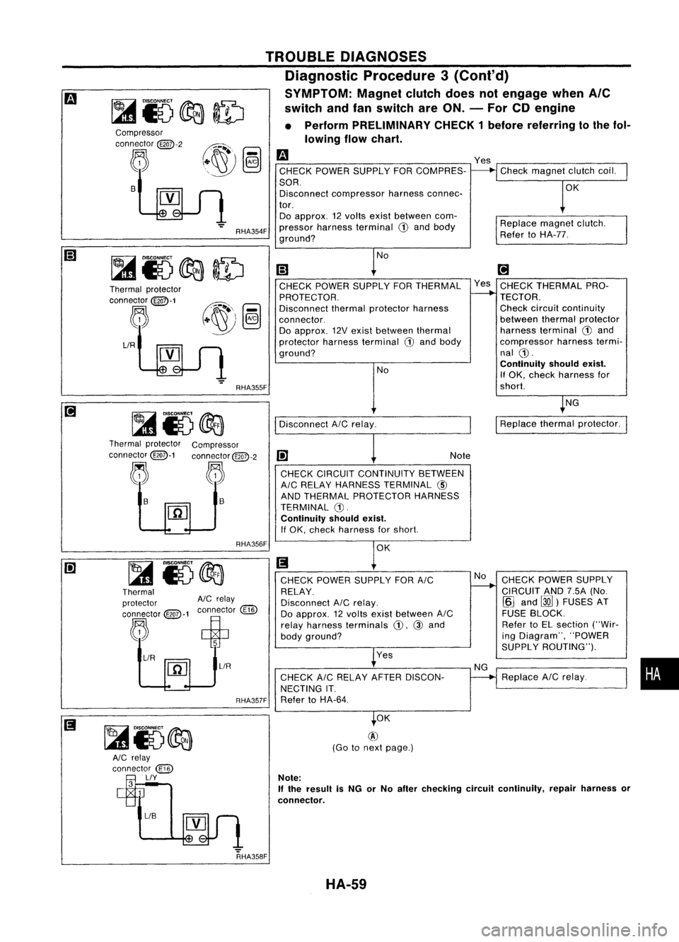
Diagnostic Procedure3(Cont'd)
SYMPTOM: Magnetclutchdoesnotengage whenAle
switch andfanswitch areON. -For CDengine
• Perform PRELIMINARY CHECK1before referring tothe fol-
lowing flowchart.
Compressor
connector
@Q7>-2
~ B
Thermal protector
connector
@Q7>-1
~
LlR
RHA354F
RHA355F
m
CHECK POWER SUPPLY FORCOMPRES-
SOR. Disconnect compressor harnessconnec-
tor. Do approx. 12volts exist between com-
pressor harness terminal
CD
and body
ground?
No
(;J
CHECK POWER SUPPLY FORTHERMAL
PROTECTOR.
Disconnect thermalprotector harness
connector. Do approx. 12Vexist between thermal
protector harnessterminal
G)
and body
ground?
NoYes
Check magnet clutchcoil.
OK
Replace magnetclutch.
Refer toHA-77.
[!]
Yes CHECK THERMAL PRO-
TECTOR. Check circuitcontinuity
between thermalprotector
harness terminal
G)
and
compressor harnesstermi-
nal
CD.
Continuity shouldexist.
If OK. check harness for
short.
NG
Disconnect AICrelay.
I
Replace thermalprotector.
Thermal protector Compressor
connector@-1 connector@QD-2
j. ~~
1-
I1iJ
RHA356F Note
CHECK CIRCUIT CONTINUITY BETWEEN
AIC RELAY HARNESS TERMINAL
@)
AND THERMAL PROTECTOR HARNESS
TERMINAL G).
Continuity shouldexist.
If OK. check harness forshort.
OK
Thermal
protector AlCrelay
connector @:>-1connector
@])
~ ciP
~/R ~
1
~L1R
RHA357FCHECK
POWER SUPPLY FORAIC
RELAY.
Disconnect AICrelay.
Do approx. 12volts exist between AIC
relay harness terminals
CD.
@and
body ground?
Yes
CHECK AICRELAY AFTERDISCON-
NECTING IT.
Refer toHA-64. No
NG CHECK
POWER SUPPLY
CIRCUIT AND7.5A(No.
~J
and
00)
FUSES AT
FUSE BLOCK.
Refer toEL section ("Wir-
ing Diagram", "POWER
SUPPLY ROUTING").
Replace AICrelay.
•
RHA358F OK
@
(Go tonext page.)
Note:
If
the result isNG orNo after checking circuitcontinuity, repairharness or
connector.
HA-59
Page 1652 of 1701

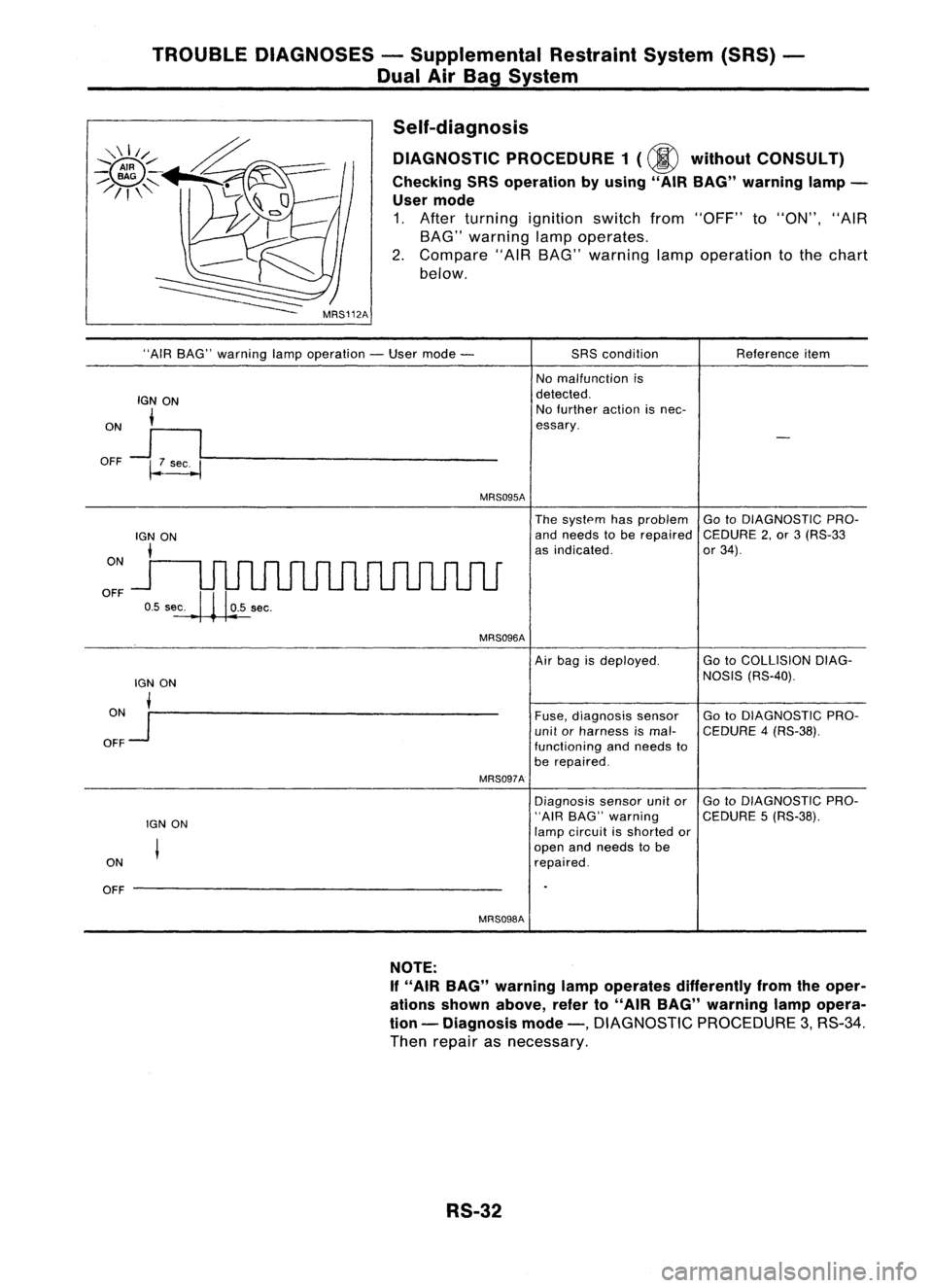
TROUBLEDIAGNOSES -Supplemental RestraintSystem(SRS)-
Dual AirBag System
Self-diagnosis DIAGNOSTIC PROCEDURE 1(@ without CONSULT)
Checking SRSoperation byusing" AIRBAG" warning lamp-
User mode
1. After turning ignition switchfrom"OFF" to"ON", "AIR
BAG" warning lampoperates.
2. Compare "AIRBAG" warning lampoperation tothe chart
below.
"AIR BAG" warning lampoperation -User mode -
IGN ON
i
ON
J
I
OFF ~~----------------
MRS095A
SRS
condition
No malfunction is
detected. No further actionisnec-
essary. Reference
item
ON
OFF
The
system hasproblem GotoDIAGNOSTIC PRO-
and needs tobe repaired CEDURE2,or 3(RS-33
as indicated. or34).
MRS096A
lGN ON
ON •
OFF
Jr--------------------
MRS097A
IGN ON
ON
OFF --------------------
MRS098A
Air
bag isdeployed. GotoCOLLISION DIAG-
NOSIS (RS-40).
Fuse, diagnosis sensor GotoDIAGNOSTIC PRO-
unit orharness ismal- CEDURE 4(RS-38).
functioning andneeds to
be repaired.
Diagnosis sensorunitor GotoDIAGNOSTIC PRO-
"AIR BAG" warning CEDURE5(RS-38).
lamp circuit isshorted or
open andneeds tobe
repaired.
NOTE:
If "AIR BAG" warning lampoperates differently fromtheoper-
ations shown above, referto"AIR BAG" warning lampopera-
tion -Diagnosis mode-,
DIAGNOSTIC PROCEDURE3,RS-34.
Then repair asnecessary.
RS-32