1995 NISSAN ALMERA N15 Motor oil
[x] Cancel search: Motor oilPage 39 of 1701

REMOVALANDINSTALLATION
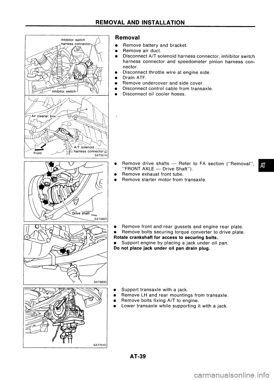
Removal
• Remove batteryandbracket.
• Remove airduct.
• Disconnect
AIT
solenoid harnessconnector, inhibitorswitch
harness connector andspeedometer pinionharness con-
nector.
• Disconnect throttlewireatengine side.
• Drain ATF.
• Remove undercover andside cover.
• Disconnect controlcablefromtransaxle.
• Disconnect oilcooler hoses.
• Remove driveshafts -Refer toFA section ("Removal", •
"FRONT AXLE-Drive Shaft").
• Remove exhaustfronttube.
• Remove startermotorfromtransaxle.
• Remove frontandrear gussets andengine rearplate.
• Remove boltssecuring torqueconverter todrive plate.
Rotate crankshaft foraccess tosecuring bolts.
• Support enginebyplacing ajack under oilpan.
Do not place jackunder oilpan drain plug.
• Support transaxle withajack.
• Remove LHand rear mountings fromtransaxle.
• Remove boltsfixing
AIT
toengine.
• Lower transaxle whilesupporting
it
with ajack.
AT-39
Page 309 of 1701

ANTI-LOCKBRAKESYSTEM
System Components
Dual proportioning
valve
Rearwheel sensors
For LHD models, controlunit
is located onthe opposite side.
SBR048DB
Control unit
s::';o~'~W.
r
I .I
Tooth~ Sensorrotor
/ ~m~f onetooth
v:~-- System
Description
SENSOR
The sensor unitconsists ofagear-shaped sensorrotoranda
sensor element. Theelement contains abar magnet around
which acoil iswound. Thesensor isinstalled onthe back side
of the brake rotor.Sine-wave currentisgenerated bythe sen-
sor asthe wheel rotates. Thefrequency andvoltage increase(s) •
as the rotating speedincreases. :•
V: Induced electromotive force
SBR124B
SBR049DA CONTROL
UNIT
The control unitcomputes thewheel rotating speedbythe sig-
nal current sentfrom thesensor. Thenitsupplies aDC current
to the actuator solenoid valve.Italso controls ON-OFFopera-
tion ofthe valve relayandmotor relay.Ifany electrical malfunc-
tion should bedetected inthe system, thecontrol unitcauses
the warning lamptolight up.Inthis condition, theASS willbe
deactivated bythe control unit,andthevehicle's brakesystem
reverts tonormal operation.
BR-39
Page 325 of 1701

TROUBLEDIAGNOSES
Self-diagnosis (ForEurope) (Cont'd)
MALFUNCTION CODE/SYMPTOM CHART
Code No.
Malfunctioningpart Diagnostic
procedure
(No. ofwarning lampflashes)
45
Actuator
frontleftoutlet solenoid valve
3
46
Actuator
frontleftinlet solenoid valve
3
41
Actuator
frontrightoutlet solenoid valve
3
42
Actuator
frontrightinletsolenoid valve
3
51
Actuator
rearright outlet solenoid valve
3
52
Actuatorrearright inletsolenoid valve
3
55
Actuator
rearleftoutlet solenoid valve
3
56
Actuator
rearleftinlet solenoid valve
3
25
Frontleftsensor (open-circuit)
4
26
Front
leftsensor (short-circuit)
4
21
Frontrightsensor (open-circuit)
4
22
Front
rightsensor (short-circuit)
4
35
Rearleftsensor (open-circuit)
4
36
Rear
leftsensor (short-circuit)
4
31
Rearrightsensor (open-circuit)
4
32
Rearrightsensor (short-circuit)
4
18
Sensorrotor
4
61
Actuatormotorormotor relay
5
63
Solenoidvalverelay
6
57
Powersupply (Lowvoltage)
7
71
Controlunit
8
Control unitpower supply circuit
Warning lampstays onwhen igni-Warning
lampbulbcircuit
tion switch isturned on Control
unitorcontrol unitconnector
2
Solenoid valverelaystuck
Power supply forsolenoid valverelaycoil
Warning lampstays on,during
Controlunit
-
self-diagnosis
Warning lampdoesnotcome onFuse, warning lampbulborwarning lampcircuit
1
when ignition switchisturned onControl unit
Warning lampdoes notcome on
Control unit
during self-diagnosis
-
Pedal vibration andnoise
-
9
Long stopping distance
-
10
Unexpected pedalaction
-
11
ABS does notwork
-
12
ABS works frequently
-
13
BR-55
•
Page 374 of 1701

CONTENTS(Conl'd.)
Front FogLamp Aiming Adjustment.. 101
Rear FogLamp/Wiring Diagram-R/FOG -102
Turn Signal andHazard Warning Lamps/
Schematic 106
Turn Signal andHazard Warning
Lamps/Wiring Diagram-TURN - 107
Turn Signal andHazard Warning
Lamps/Trouble Diagnoses 113
Combination FlasherUnitCheck 113
Bulb Specifications 114
INTERIOR LAMP 115
Illumination/Schematic 115
Illumination/Wiring Diagram-ILL - 116
Interior, Spot,Trunk Room andLuggage
Room Lamps/Wiring Diagram-INT/L - 122
Bulb Specifications 126
METER ANDGAUGES 127
Combination Meter 127
Speedometer, Tachometer,Temp.andFuel
Gauges/Wiring Diagram-METER - 129
Inspection/Fuel GaugeandWater
Temperature Gauge 133
Inspection/Tachometer 134
Inspection/Speedometer andVehicle Speed
Sensor 135
Fuel Tank Gauge UnitCheck 137
Thermal Transmitter Check 137
Vehicle SpeedSensor SignalCheck 137
WARNING LAMPSANDBUZZER 138
Warning Lamps/Schematic 138
Warning Lamps/Wiring Diagram-WARN -139
Oil Pressure SwitchCheck 151
Fuel Warning LampSensor Check 151
Diode Check 151
Warning BuzzerUnit... 151
Warning Buzzer/System Description 152
Warning Buzzer/Wiring Diagram
- BUZZER - 154
Components Inspection-Warning Buzzer 157
WIPER ANDWASHER 160
Front Wiper andWasher/System Description160
Front Wiper andWasher/Wiring Diagram
- WIPER - 162
Front Wiper Amplifier Check 166
Front Wiper Installation andAdjustment.. 166
Front Wiper Linkage 167
Front Washer NozzleAdjustment... 168
Front Washer TubeLayout 168
Rear Wiper andWasher/System Description169Rear
Wiper andWasher/Wiring Diagram
- WIP/R - 171
Rear Wiper Amplifier Check 175
Rear Wiper Installation andAdjustment.. 175
Rear Washer NozzleAdjustment 175
Rear Washer TubeLayout.. 176
Check Valve(forrear washer) 176
Headlamp WiperandWasher/Wiring Diagram
- HLC - 177
Headlamp WiperMotorCheck 179
Headlamp WiperInstallation 179
Headlamp WasherTubeLayout.. 179
Check Valve(Forheadlamp washer) 179
POWER WINDOW 180
System Description 180
Schematic 183
Wiring Diagram -WINDOW - 185
Trouble Diagnoses 197
POWER DOORLOCK 198
System Description 198
Schematic 200
Wiring Diagram -D/LOCK - 202
Trouble Diagnoses -Type 1(For Europe and
Austral ia) 212
Trouble Diagnoses -Type 2(Except for
Europe andAustralia) 216
POWER DOORMIRROR 220
Wiring Diagram -MIRROR - 220
ELECTRIC SUNROOF 224
Wiring Diagram -SROOF - 224
HORN, CIGARETTE LIGHTERANDCLOCK 226
Wiring Diagram -HORN - 226
REAR WINDOW DEFOGGER ANDDOOR
MIRROR DEFOGGER 230
System Description (Formodels withdaytime
light system) 230
Wirin.g Diagram -DEF - 231
Filament Check 235
Fi lament Repai
r
236
AUDIO ANDANTENNA 237
Audio/System Description 237
Wiring Diagram -AUDIO - 238
Radio FuseCheck 243
Location ofAntenna 243
Antenna RodReplacement.. 243
HEATED SEAT 245
Wiring Diagram -H/SEAT - 245
NATS (Nissan Anti-Theft System) 247
System Description 247
System Composition 247
Page 392 of 1701

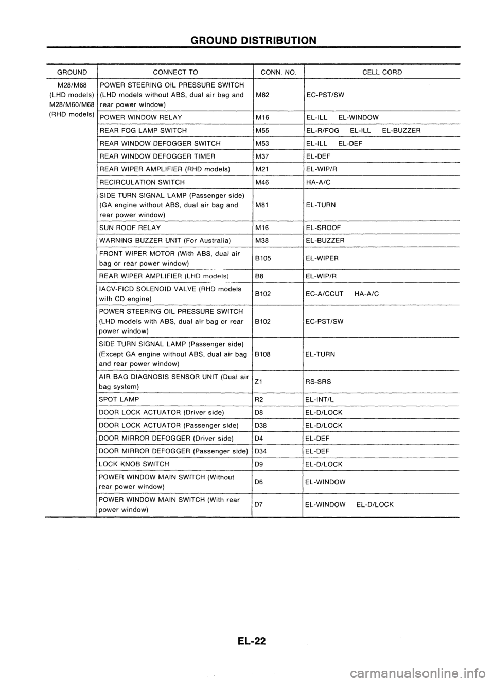
GROUNDDISTRIBUTION
GROUND CONNECTTO CONN.
NO. CELLCORD
E37/E51 AIRBAG DIAGNOSIS SENSORUNIT(Single
E108 RS-SRS
air bag system)
BRAKE FLUIDLEVEL SWITCH E2EL-WARN
CLEARANCE LAMPLH E50EL-TAILIL
CLEARANCE LAMPRH E33EL-TAILIL
COOLING FANMOTOR-1 (1-modetype) E45 EC-COOLIFHA-A/C
COOLING FANMOTOR-1 (2-modetype-GA
E66 EC-COOLIF
HA-A/C
engine forEurope)
COOLING FANMOTOR-1 (2-modetype-ex-
E46 EC-COOLIF
HA-A/C
eept GAengine forEurope)
COOLING FANMOTOR-2 (1-modetype)
E39 EC-COOLIFHA-A/C
-
COOLING FANMOTOR-2 (2-modetype-GA
E67 EC-COOLiF
HA-A/C
engine forEurope)
COOLING FANMOTOR-2 (2-modetype-ex-
E40 EC-COOLIFHA-A/C
eept GAengine forEurope)
COOLING FANRELAY-1 E12
EC-COOLIFHA-A/C
COOLING FANRELAY-2 E17
EC-COOLIFHA-A/C
COOLING FANRELAY-3 E18EC-COOLIF
HA-A/C
DAYTIME LIGHTUNIT E119EL-DTRL
FRONT FOGLAMP LH E52EL-F/FOG
FRONT FOGLAMP RH
E36EL-F/FOG
FRONT TURNSIGNAL LAMPLH E53EC-TURN
FRONT TURNSIGNAL LAMPRH E32EC-TURN
FRONT WIPERANDWASHER SWITCH E113
EL-WIPER
FUEL FILTER SWITCH
E5EL-WARN
HEADLAMP AIMINGMOTOR UNITLH E48
EL-AIM
HEADLAMP AIMINGMOTOR UNITRH E35 EL-AIM
HEADLAMP LH E49EL-H/LAMP
EL-DTRL
HEADLAMP RH E34EL-H/LAMP
EL-DTRL
HEADLAMP WIPERMOTOR LH E44
EL-HLC
HEADLAMP WIPERMOTOR RH E41EL-HLC
IACV-FICD SOLENOID VALVE(LHDmodels
.
E65 EC-A/CCUTHA-A/C
with CD20 engine)
INHIBITOR SWITCH E222EC-PNP/SWAT-A
IT EL-START
NEUTRAL POSITION SWITCH E220EC-PNP/SW
POWER STEERING OILPRESSURE SWITCH
E3 EC-PST/SW
(RHO models withgasoline engine)
REAR FOGLAMP RELAY E20EL-R/FOG
REAR WIPER ANDWASHER SWITCH E112EL-WIP/R
REAR WIPER RELAY E15EL-WIP/R
SIDE TURN SIGNAL LAMP(Driver side) E1 EL-TURN
WASHER FLUIDLEVEL SWITCH E30EL-WARN
EL-20
Page 394 of 1701

GROUNDDISTRIBUTION
GROUND CONNECT
TO CONN.NO.
CELLCORD
M28/M68
POWERSTEERING OILPRESSURE SWITCH
(LHD models) (LHDmodels withoutA8S,dualairbag and M82 EC-PST/SW
M28/M60/M68
rearpower window)
(RHD models)
POWERWINDOW RELAY
M16EL-ILLEL-WINDOW
REAR FOGLAMP SWITCH M55EL-R/FOGEL-ILLEL-8UZZER
REAR WINDOW DEFOGGER SWITCH M53EL-ILLEL-DEF
REAR WINDOW DEFOGGER TIMER M37EL-DEF
REAR WIPER AMPLIFIER (RHDmodels) M21EL-WIP/R
RECIRCULATION SWITCH M46HA-A/C
SIDE TURN SIGNAL LAMP(Passenger side)
(GA engine without A8S,dualairbag and M81 EL-TURN
rear power window)
SUN ROOF RELAY M16EL-SROOF
WARNING 8UZZERUNIT(ForAustralia)
M38EL-8UZZER
FRONT WIPERMOTOR (WithA8S,dualair
8105 EL-WIPER
bag orrear power window)
-_._-
-
REAR WIPER AMPLIFIER (LHDmodelsl 88EL-WIP/R
0-
IACV-FICD SOLENOID VALVE(RHDmodels
8102 EC-A/CCUTHA-A/C
with CDengine)
POWER STEERING OILPRESSURE SWITCH
(LHD models withASS, dualairbag orrear 8102 EC-PST/SW
power window)
SIDE TURN SIGNAL LAMP(Passenger side)
(Except GAengine without A8S,dualairbag 8108 EL-TURN
and rear power window)
AIR 8AG DIAGNOSIS SENSORUNIT(Dual air
Z1 RS-SRS
bag system)
SPOT LAMP
R2EL-INT/L
DOOR LOCKACTUATOR (Driverside)
D8 EL-D/LOCK
DOOR LOCKACTUATOR (Passengerside)
D38 EL-D/LOCK
DOOR MIRROR DEFOGGER (Driverside)
D4 EL-DEF
DOOR MIRROR DEFOGGER (Passengerside)
D34 EL-DEF
LOCK KN08 SWITCH
D9EL-D/LOCK
POWER WINDOW MAINSWITCH (Without
D6 EL-WINDOW
rear power window)
POWER WINDOW MAINSWITCH (Withrear
D7 EL-WINDOW EL-D/LOCK
power window)
EL-22
Page 772 of 1701

ON-BOARDDIAGNOSTIC SYSTEMDESCRIPTION
CONSULT (Cont'd)
ACTIVE TESTMODE
TEST ITEM CONDITION JUDGEMENT
CHECKITEM(REMEDY)
• Engine: Returntothe original
•Harness andconnector
FUEL INJECTION trouble
condition If
trouble symptom disappears,
•Fuel injectors
• Change theamount offuel see
CHECK ITEM.
injection usingCONSULT . •
Oxygen sensor*1
• Engine: Afterwarming up,idle
IACV-AACIV the
engine.
Enginespeedchanges according •Harness andconnector
OPENING •
Change theIACV-AAC valve
tothe opening percent. •
IACV-AAC valve
opening percentusingCON-
SULT.
• Engine: Returntothe original
•Harness andconnector
ENG COOLANT trouble
condition
Iftrouble symptom disappears, •
Engine coolant temperature
TEMP •
Change theengine coolant
.
see CHECK ITEM. sensor
temperature indicationusing
•Fuel injectors
CONSULT.
• Engine: Returntothe original
trouble condition
Iftrouble symptom disappears,
IGNITION TIMING•
Timing light:Set •
Adjust initialignition timing
• Retard theignition timingusingsee
CHECK ITEM.
CONSULT .
• Engine: Afterwarming up,idle •
Harness andconnector
the engine. •
Compression
POWER •
A/C switch "OFF"
Enginerunsrough ordies . •
Injectors
BALANCE •
Shift lever "N" •
Power transistor
• Cut offeach injector signalone •
Spark plugs
at atime using CONSULT. •
Ignition coils
• Ignition switch:ON
COOLING FAN*3•
Turn thecooling fan"ON" and
Cooling fanmoves andstops. •
Harness andconnector
"OFF", or"LOW" and"HI" •
Cooling fanmotor
and "OFF" usingCONSULT .
• Ignition switch:ON(Engine
FUEL PUMP stopped)
Fuelpump relaymakes theoper- •Harness andconnector
• Turn thefuel pump relay"ON"
RELAY and"OFF" usingCONSULT ating
sound. •
Fuel pump relay
and listen tooperating sound.
EGRC SOLENOID
VALVE (EVAP canister
•Ignition switch:ON
purge control
•Turn solenoid valve"ON" and Solenoid
valvemakes anoperat- •
Harness andconnector
solenoid valveor
EGR valve
&
"OFF"
withtheCONSULT andingsound. •
Solenoid valve
EVAP canister listen
tooperating sound.
purge control
solenoid valve)
•Ignition switch:ON
VALVE TIMING •
Turn solenoid valve"ON" and Solenoid
valvemakes anoperat- •
Harness andconnector
SOL*2 "OFF"
usingCONSULT anding
sound. •
Solenoid valve
listen tooperating sound.
SELF-LEARNING •
Inthis test, thecoefficient ofself-learning controlmixture ratioreturns tothe original coefficient by
CONT touching
"CLEAR" onthe screen.
*1: Heated oxygen sensor(ForEurope andIsrael, andAustralia A/Tmodels)
Oxygen sensor(Except forEurope andIsrael, andAustralia A/Tmodels)
*2: GA16DE except forEurope andIsrael
*3: GA16DE engine A/Tmodels forEurope without heavydutykithave a2- step control [ON/OFF] system."LOW"and"HI"
are shown onCONSULT screentorepresent "ON"condition.
EC-53
•
Page 774 of 1701

ON-BOARDDIAGNOSTIC SYSTEMDESCRIPTION
CONSULT (Conl'd)
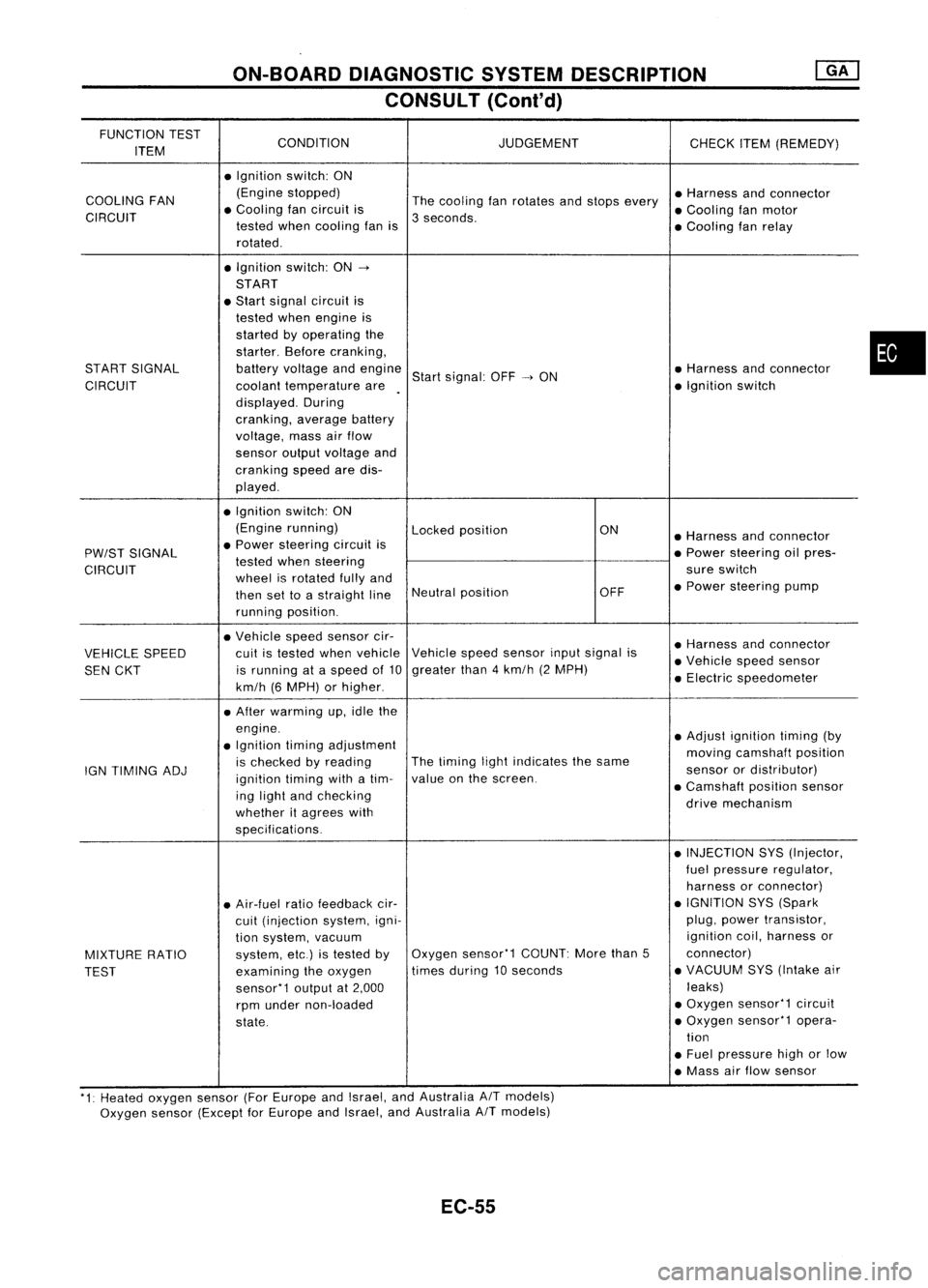
FUNCTION TEST
CONDITION JUDGEMENT
ITEM CHECK
ITEM(REMEDY)
• Ignition switch:ON
COOLING FAN (Engine
stopped)
Thecooling fanrotates andstops every •
Harness andconnector
CIRCUIT •
Cooling fancircuit is
3seconds. •
Cooling fanmotor
tested whencooling fanis
•Cooling fanrelay
rotated .
• Ignition switch:ON-.
START
• Start signal circuit is
tested whenengine is
started byoperating the
starter. Beforecranking,
START SIGNAL batteryvoltage andengine
Startsignal: OFF-.ON •
Harness andconnector
CIRCUIT coolanttemperature are •
Ignition switch
displayed. During
cranking, averagebattery
voltage, massairflow
sensor outputvoltage and
cranking speedaredis-
played .
• Ignition switch:ON
(Engine running)
Lockedposition ON
•Harness andconnector
PW/ST SIGNAL •
Power steering circuitis
•Power steering oilpres-
tested whensteering
CIRCUIT wheelisrotated fullyand sure
switch
then settoastraight lineNeutral
position OFF•
Power steering pump
running position.
• Vehicle speedsensor cir-
•Harness andconnector
VEHICLE SPEED cuit
istested whenvehicle Vehicle
speedsensor inputsignal is
•Vehicle speedsensor
SEN CKT is
running ataspeed of10 greater
than4km/h (2MPH)
•Electric speedometer
km/h (6MPH) orhigher .
• After warming up,idle the
engine. •Adjust ignition timing(by
• Ignition timingadjustment
movingcamshaft position
IGN TIMING ADJ is
checked byreading The
timing lightindicates thesame
sensorordistributor)
ignition timingwithatim- value
onthe screen.
•Camshaft positionsensor
ing light andchecking
drivemechanism
whether itagrees with
specifications.
•INJECTION SYS(Injector,
fuel pressure regulator,
harness orconnector)
• Air-fuel ratiofeedback cir- •
IGNITION SYS(Spark
cuit (injection system,igni- plug,
power transistor,
tion system, vacuum ignition
coil,harness or
MIXTURE RATIO system,
etc.)istested byOxygen
sensor'1 COUNT:Morethan5 connector)
TEST examining
theoxygen times
during 10seconds •
VACUUM SYS(Intake air
sensor'1 outputat2,000 leaks)
rpm under non-loaded •
Oxygen sensor'1 circuit
state. •
Oxygen sensor'1 opera-
tion
• Fuel pressure highorlow
• Mass airflow sensor
'1: Heated oxygen sensor(ForEurope andIsrael, andAustralia AITmodels)
Oxygen sensor(Except forEurope andIsrael, andAustralia
A/T
models)
EC-55
•