Page 978 of 1701

ON-BOARDDIAGNOSTIC SYSTEMDESCRIPTION
CONSULT (Conl'd)
ACTIVE TESTMODE
TEST ITEM CONDITION JUDGEMENTCHECKITEM(REMEDY)
• Engine: Returntothe original
•Harness andconnector
FUEL INJECTION trouble
condition
Iftrouble symptom disappears,
•Fuel injectors
• Change theamount offuel
seeCHECK ITEM.
•Heated oxygen sensor
injection usingCONSULT .
• Engine: Afterwarming up,idle
IACV-AACIV the
engine.
Enginespeedchanges according •Harness andconnector
OPENING •
Change theIACV-AAC valve
tothe opening percent. •
IACV-AAC valve
opening percentusingCON-
SULT.
• Engine: Returntothe original
•Harness andconnector
ENG COOLANT trouble
condition
Iftrouble symptom disappears, •
Engine coolant temperature
• Change theengine coolant
.
TEMP see
CHECK ITEM. sensor
temperature indicationusing
•Fuel injectors
CONSULT .
• Engine: Returntothe original
trouble condition
Iftrouble symptom disappears,
IGNITION TIMING•Timing light:Set •
Adjust initialignition timing
• Retard theignition timingusingsee
CHECK ITEM.
CONSULT.
• Engine: Afterwarming up,idle •
Harness andconnector
the engine. •
Compression
POWER
•
AIC
switch "OFF"
Enginerunsrough ordies. •
Injectors
BALANCE •
Shift lever "N" •
Power transistor
• Cut offeach injector signalone •
Spark plugs
at atime using CONSULT . •
Ignition coils
• Ignition switch:ON
•Harness andconnector
COOLING FAN•
Turn thecooling fan"ON" andCooling
fanmoves andstops.
•Cooling fanmotor
"OFF" usingCONSULT .
• Ignition switch:ON(Engine
FUEL PUMP stopped)
Fuelpump relaymakes theoper- •
Harness andconnector
RELAY •
Turn thefuel pump relay"ON"
atingsound. •
Fuel pump relay
and "OFF" usingCONSULT
and listen tooperating sound.
EGRC •
Ignition switch:ON
• Turn solenoid valve"ON"and Solenoid
valvemakes anoperat- •
Harness andconnector
SOLENOID "OFF"withtheCONSULT andingsound. •
Solenoid valve
VALVE listentooperating sound.
SELF-LEARNING •
In this test, thecoefficient ofself-learning controlmixture ratioreturns tothe original coefficient by
CONT touching
"CLEAR" onthe screen.
EC-259
•
Page 1154 of 1701
SEC.214
10
~ :N.m (kg-m, in-Ib)
ENGINE
COOLING SYSTEM
Radiator
~~ 3.7.5.0(0.38-0.51, 33.0•44.3)
~~ 3.8.4.5 (0.39 •0.46, 33.9.39.9)
. I
L!
\[jj
3.'-4.5 (0.39 -0.45,3>' -39.')
~,,~ 'fl
'~~WI-
1
I
--
5'\
,
),
"~
" It, -~ ~,.../ "---./"-- ~~
n.- /
i ~
r~ ~ ~'".~
i
@
'0)"
I
I
Jl~J)
1~~
6.86 •
~ "" <>!.
0
(0.70,60.7)
",,~~@
SLC991AB
G)
Reservoir tank
@
Reservoir tankbracket
@
Radiator cap
@
Mounting bracket
@
Upper hose
@
Washer
(J)
Drain plug
@
Mounting rubber
@
Oilcooler hose(AfTmodels)
@l
Radiator
@
Lower hose
@
Cooling fan
@
Cooling fanmotor
Cooling fancontrol system
• Cooling fansarecontrolled bythe ECM. Fordetails, referto
EC section ("Cooling FanControl", "TROUBLE DIAG-
NOSES").
Refilling enginecoolant
• For details onrefilling enginecoolant, refertoMA section
("REFILLING ENGINECOOLANT", "ChangingEngine
Coolant").
LC-16
Page 1163 of 1701
SEC.214
10
ENGINE
COOLING SYSTEM
Radiator
SLC039BA
•
CD
Reservoir tank
@
Reservoir tankbracket
@
Radiator cap
@
Mounting bracket
CID
Upper hose
@
Washer
(J)
Drain plug
CID
Mounting rubber
@
Oilcooler hose
(AfT
models)
@)
Radiator
@
Lower hose
@
Cooling fan
@
Cooling fanmotor
Cooling fancontrol system
• Cooling fansarecontrolled bythe ECM. Fordetails, referto
EC section ("Cooling FanControl", "TROUBLE
DIAGNOSES").
Refilling enginecoolant
• For details onrefilling enginecoolant, refertoMA section
("REFILLING ENGINECOOLANT", "ChangingEngine
Coolant").
LC-25
Page 1238 of 1701

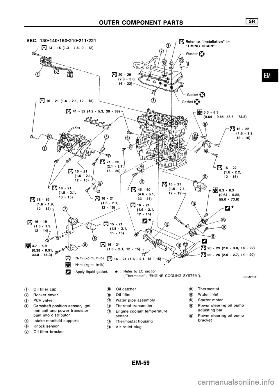
OUTERCOMPONENT PARTS
•
SEM231F
SEC.
130-140-150-210-211-221
~ __to:J
13•16 (1.3 -1.6, 9.12)
to:J
16•21 (1.6. 2.1,12. 15)
to:J
20•29
(2.0 •3.0,
14 .22)
to:J
41-52 (4.2 -5.3, 30-38)
~---- D_?
. 'J ~
~~~ 0
-t::;-.....~ /,
0
to:J
21-26 ./"
(2.1. 2.7, ,./"~/'
12 -1~)
fs\
19-~~7
~ to:J
16•21
Q
to:J
18. 21 ,
to:J
45_60 (1.6-2.1, 0
Ii]
6.3 _8.3
(1.8 •2.1, (4.6•6.1, 12•15)
1
(0.64•0.85,
to:J
16•19 13-15)
to:J
16•21 33•44)
(1.6 -1.9, (1.6-2.1,
to:J
16•21
12 -14)
12•15)
t"J
16•,.
f"-~
t"J
15•21
r::!
*
H
...----4lJ
~~'. '1~
J
r \~ ~~'..,:;
1,
~Q.
/¥i-;:
--'Il
1il3.7 -5.0
J~
--A)
to:J
16-21
~11V>/
(0.38 _0.51, A~ - (1.6.2.1,12•15)\...,//
~to:J
20.29(2.0-3.0, 14-22)
33.0 •44.3)
Y
&'/-
:f~l
to:J
20•26 (2.0 •2.7, 14-20)
to:J :
N'm (kg-m, fl-Ib)
to:J
16-21 (1.6 -2.1, 12-15)~/
Ii] :
N'm (kg-m, in-Ib) •
~ :Apply
liquidgasket.
*:
Refer toLC section
("Thermostat", "ENGINECOOLING SYSTEM").
G)
Oilfiller cap
@
Oilcatcher
@
Thermostat
@
Rocker cover
@
Oilfilter
@
Water inlet
@
PCVvalve
@
Water pipeassembly
@
Starter motor
@
Camshaft
positionsensor,igni-
@
Thermal transmitter
@
Power steering oilpump
tion coiland power transistor
@
Engine coolant temperature adjusting
bar
built intodistributor
sensor
@
Power
steering oilpump
@
Intake manifold supports
@
Thermostat housing bracket
@
Knock sensor
@
Airrelief plug
rJ)
Oilfilter bracket
EM-59
Page 1250 of 1701
TIMINGCHAIN
Removal (ConI'd)
17. Remove timingchainguide.
18. Remove camshaft sprockets.
19. Remove camshafts, camshaftbrackets, oiltubes andbaffle
plate.
•
Loosen innumerical order.
SEM7870A
20.Remove startermotor.
21. Remove thefollowing waterhoses.
• Water hoseforcylinder block.
• Water hosesfromheater.
22. Remove knocksensor harness connector.
EM-71
Page 1257 of 1701
SEM354D
f'J
liquid gasket
Apply
liquidgasket
to the hatched area.
o ~
LHcamshaft endbracket
SEM075DA
RH camShaft./'::~nd bracket
brackey
0
Edb kt
~ "nrace
(1)
~~~;~ ~.o
o.
00'{'
NO.1 to4
0
brackets LHcamshaft
NO.1 to4brackets bracket
SEM098DA TIMING
CHAIN
Installation (Cont'd)
17. Install starter motor.
18. Remove alltraces ofliquid gasket frommating surface ofLH
camshaft endbracket.
•. Also remove tracesofliquid gasket frommating surface of
cylinder head.
19. Apply liquidgasket tomating surface ofLH camshaft end
bracket asshown inillustration.
• Use Genuine LiquidGasket orequivalent.
20. Install camshafts, camshaftbrackets,oiltubes andbaffle
plate.
• Position camshaft.
• LHcamshaft keyatabout 12o'clock
• RHcamshaft keyatabout 10o'clock
Apply engine oiltobearings andcam surfaces ofcamshafts
before installing them.
• Position camshaft bracketsasshown inillustration.
Apply engine oiltothreads andseating surfaces ofcamshaft
bracket boltsbefore installing them.
EM-78
Page 1292 of 1701
Rightside
SEC. 130.135.185.186.210.213.233
~: N.m(kg-m. in-Ib)
[ClJ :
N.m (kg-m. ft-Ib)
OUTER
COMPONENT PARTS
I~
16-21
(1.6 -2.1,
12-
15)7
I
.~
SEM044FA
•
G)
Starter motor
@
Injection pump
@
Injection tube
@
Thermostat housing
@
Injection nozzle
@
Spill tube
!J)
Water outlet
@
Beltcover
EM-113
@
Timing belt
@
Injection pumpsprocket
@
Rear camshaft sprocket
@
Rear backcover
@
Oilcooler
@
Gasket
Page 1412 of 1701

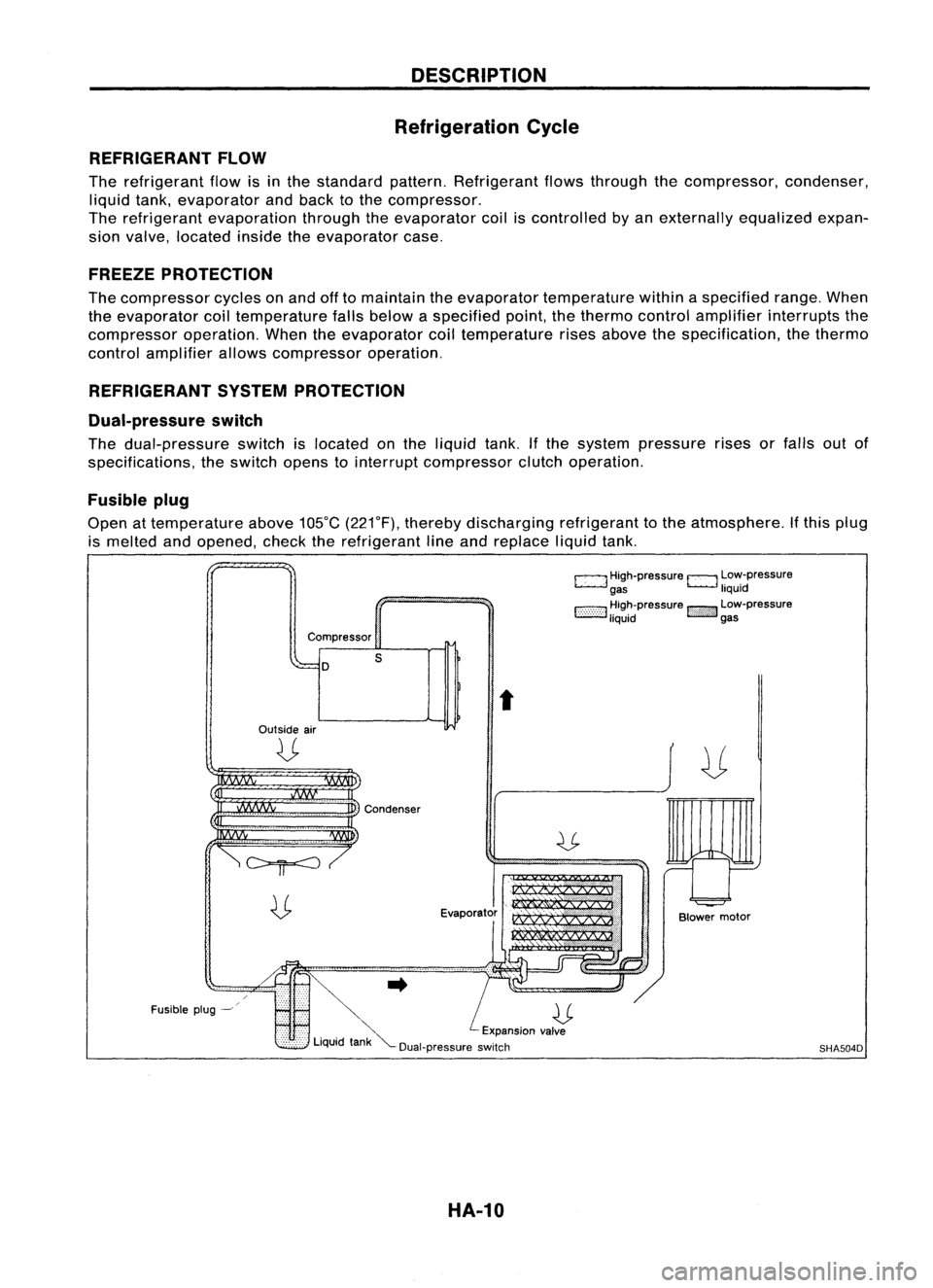
DESCRIPTION
Refrigeration Cycle
REFRIGERANT FLOW
The refrigerant flowisinthe standard pattern.Refrigerant flowsthrough thecompressor, condenser,
liquid tank,evaporator andback tothe compressor.
The refrigerant evaporation throughtheevaporator coiliscontrolled byan externally equalizedexpan-
sion valve, located insidetheevaporator case.
FREEZE PROTECTION
The compressor cyclesonand offtomaintain theevaporator temperature withinaspecified range.When
the evaporator coiltemperature fallsbelow aspecified point,thethermo controlamplifier interrupts the
compressor operation.Whentheevaporator coiltemperature risesabove thespecification, thethermo
control amplifier allowscompressor operation.
REFRIGERANT SYSTEMPROTECTION
Dual-pressure switch
The dual-pressure switchislocated onthe liquid tank.Ifthe system pressure risesorfalls outof
specifications, theswitch openstointerrupt compressor clutchoperation.
Fusible plug
Open attemperature above105°C(221°F), thereby discharging refrigeranttothe atmosphere. Ifthis plug
is melted andopened, checktherefrigerant lineand replace liquidtank.
c:::::.J
High-pressure
EJ
Low-pressure
gas liquid
1:-:-:-:-::-:-::-:-:1
~~~~pressure
!::i'i'i':}':J
~~:-pressure
Compressor
D
Outside air
U
s
t
Fusible plug-~
~..
U
'" Expansionvalve
Liquid tank"'--Dual-pressure switch
HA-10
Blower
motor
SHA504D