1995 NISSAN ALMERA N15 oil change
[x] Cancel search: oil changePage 22 of 1701

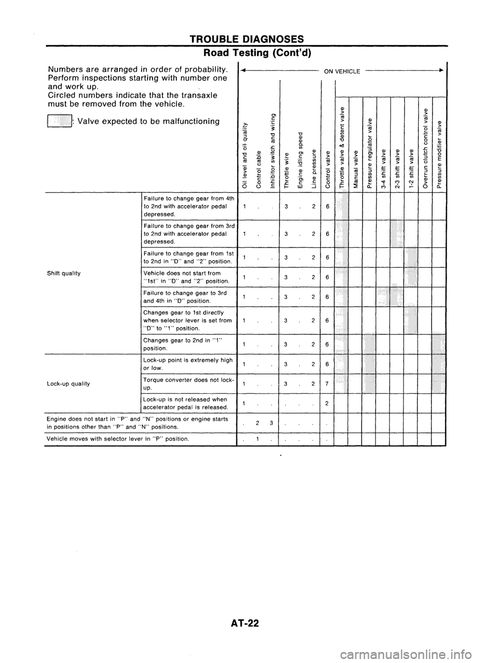
TROUBLEDIAGNOSES
Road Testing (Cont'd)
Numbers arearranged inorder ofprobability.
~
ONVEHICLE
..
Perform inspections startingwithnumber one
and work up.
Circled numbers indicatethatthetransaxle
must beremoved fromthevehicle.
(J)(J)
> >
01
0;
0;
. Valve expected tobe malfunctioning
c:
>
(J)
~ .;::
>>
(J)
.~
c
0;
>
0;
(J)
>
e
0;
"0 "0
Q)
C
>
::J
c:(J)
.8
rr
III
(J)
"0
0
~
0.
oil
III
<.>
'0
J::.
rtl
:;
J::.
ii
(J)
£
~(J)
(J)
(J) (J)
(J)(J)
£
"0
.~
~
01
>>
>
01
>>>
0
c: :0 c:
::J
0;0;
~
0;
0;0;
::J
E
III III
rtl
.~
rtl
0;
(3
<.>
~
rtl
>>
> >
>>
a; ~
(J) ~ (J)~
;:
'E
;t:
c:
~
>
e
.8
E (J)
0.
e
E
0;
::J
J::. J::.
:c
2
::J
~
:0
.!::
::J
rtl
rtl
C
e
(J)
c
0
c:
rtlrtl
rtlrtl
li;
rtl
J::.
01
c:
.c
III
(J)
"'f
C')
C)'
>
(J)
6
0
J::.
c:
0
a: a:
u
EO
~
UJ
::i
u
~
::E
C')
N
0
Failure tochange gearfrom 4th
to 2nd with accelerator pedal
32
6
depressed.
Failure tochange gearfrom3rd
to 2nd with accelerator pedal
32
6
depressed.
Failure tochange gearfrom 1st
32
6
to 2nd in"0" and"2"position.
Shift quality Vehicledoesnotstart from
32
6
"1st" in"0" and"2"position.
Failure tochange gearto3rd
32
6
and 4thin"0" position.
Changes gearto1st directly
when selector leverisset from
32
6
"D"
to"1" position.
Changes gearto2nd in"1"
3
2
6
position.
Lock-up pointisextremely high
32
6
or low.
Lock-up quality Torque
converter doesnotlock-
32
7
up.
Lock-up isnot released when
2
accelerator pedalisreleased.
Engine doesnotstart in"P" and "N" positions orengine starts
2
3
in positions otherthan"P"and "N" positions.
Vehicle moveswithselector leverin"P" position.
AT-22
Page 743 of 1701

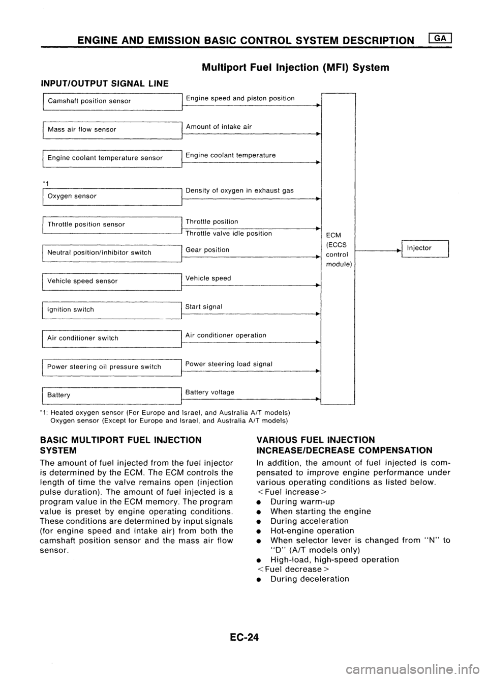
ENGINEANDEMISSION BASICCONTROL SYSTEMDESCRIPTION
Multipart FuelInjection (MFI)System
INPUT/OUTPUT SIGNALLINE
Camshaft positionsensor
Mass airflow sensor
Engine coolant temperature sensor
*1
Oxygen sensor
Throttle position sensor
Neutral position/Inhibitor switch
Vehicle speedsensor
~gnition switch
Air conditioner switch
Power steering oilpressure switch
Battery Engine
speedandpiston position
Amount ofintake air
Engine coolant temperature
Density ofoxygen inexhaust gas
Throttle position
Throttle valveidleposition
Gear position
Vehicle speed
Start signal
Air conditioner operation
Power steering loadsignal
Battery voltage ECM
(ECCS
control module) Injector
*1: Heated oxygen sensor(ForEurope andIsrael, andAustralia A/Tmodels)
Oxygen sensor(Except forEurope andIsrael, andAustralia A/Tmodels)
BASIC MULTIPORT FUELINJECTION
SYSTEM
The amount offuel injected fromthefuel injector
is determined bythe ECM. TheECM controls the
length oftime thevalve remains open(injection
pulse duration). Theamount offuel injected isa
program valueinthe ECM memory. Theprogram
value ispreset byengine operating conditions.
These conditions aredetermined byinput signals
(for engine speedandintake air)from boththe
camshaft positionsensorandthemass airflow
sensor.
VARIOUS
FUELINJECTION
INCREASE/DECREASE COMPENSATION
In addition, theamount offuel injected iscom-
pensated toimprove engineperformance under
various operating conditions aslisted below.
<
Fuel increase>
• During warm-up
• When starting theengine
• During acceleration
• Hot-engine operation
• When selector leverischanged from"N"to
"D"
(AfT
models only)
• High-load, high-speed operation
<
Fuel decrease>
• During deceleration
EC-24
Page 772 of 1701

ON-BOARDDIAGNOSTIC SYSTEMDESCRIPTION
CONSULT (Cont'd)
ACTIVE TESTMODE
TEST ITEM CONDITION JUDGEMENT
CHECKITEM(REMEDY)
• Engine: Returntothe original
•Harness andconnector
FUEL INJECTION trouble
condition If
trouble symptom disappears,
•Fuel injectors
• Change theamount offuel see
CHECK ITEM.
injection usingCONSULT . •
Oxygen sensor*1
• Engine: Afterwarming up,idle
IACV-AACIV the
engine.
Enginespeedchanges according •Harness andconnector
OPENING •
Change theIACV-AAC valve
tothe opening percent. •
IACV-AAC valve
opening percentusingCON-
SULT.
• Engine: Returntothe original
•Harness andconnector
ENG COOLANT trouble
condition
Iftrouble symptom disappears, •
Engine coolant temperature
TEMP •
Change theengine coolant
.
see CHECK ITEM. sensor
temperature indicationusing
•Fuel injectors
CONSULT.
• Engine: Returntothe original
trouble condition
Iftrouble symptom disappears,
IGNITION TIMING•
Timing light:Set •
Adjust initialignition timing
• Retard theignition timingusingsee
CHECK ITEM.
CONSULT .
• Engine: Afterwarming up,idle •
Harness andconnector
the engine. •
Compression
POWER •
A/C switch "OFF"
Enginerunsrough ordies . •
Injectors
BALANCE •
Shift lever "N" •
Power transistor
• Cut offeach injector signalone •
Spark plugs
at atime using CONSULT. •
Ignition coils
• Ignition switch:ON
COOLING FAN*3•
Turn thecooling fan"ON" and
Cooling fanmoves andstops. •
Harness andconnector
"OFF", or"LOW" and"HI" •
Cooling fanmotor
and "OFF" usingCONSULT .
• Ignition switch:ON(Engine
FUEL PUMP stopped)
Fuelpump relaymakes theoper- •Harness andconnector
• Turn thefuel pump relay"ON"
RELAY and"OFF" usingCONSULT ating
sound. •
Fuel pump relay
and listen tooperating sound.
EGRC SOLENOID
VALVE (EVAP canister
•Ignition switch:ON
purge control
•Turn solenoid valve"ON" and Solenoid
valvemakes anoperat- •
Harness andconnector
solenoid valveor
EGR valve
&
"OFF"
withtheCONSULT andingsound. •
Solenoid valve
EVAP canister listen
tooperating sound.
purge control
solenoid valve)
•Ignition switch:ON
VALVE TIMING •
Turn solenoid valve"ON" and Solenoid
valvemakes anoperat- •
Harness andconnector
SOL*2 "OFF"
usingCONSULT anding
sound. •
Solenoid valve
listen tooperating sound.
SELF-LEARNING •
Inthis test, thecoefficient ofself-learning controlmixture ratioreturns tothe original coefficient by
CONT touching
"CLEAR" onthe screen.
*1: Heated oxygen sensor(ForEurope andIsrael, andAustralia A/Tmodels)
Oxygen sensor(Except forEurope andIsrael, andAustralia A/Tmodels)
*2: GA16DE except forEurope andIsrael
*3: GA16DE engine A/Tmodels forEurope without heavydutykithave a2- step control [ON/OFF] system."LOW"and"HI"
are shown onCONSULT screentorepresent "ON"condition.
EC-53
•
Page 775 of 1701

ON-BOARDDIAGNOSTIC SYSTEMDESCRIPTION
CONSULT (Cont'd)
FUNCTION TEST
CONDITION JUDGEMENTCHECKITEM(REMEDY)
ITEM
•After warming up,idle the
engine .
• Injector operation ofeach •Injector circuit(Injector,
cylinder isstopped one harnessorconnector)
after another, andresult-
Difference inengine speedisgreater •
Ignition circuit(Spark
POWER BALANCE ant
change inengine rota-
than25rpm before andafter cutting off plug,
power transistor,
lion isexamined toevalu-
theinjector ofeach cylinder. ignition
coil,harness or
ate combustion ofeach connector)
cylinder. (Thisisonly dis- •Compression
played formodels wherea •
Valve timing
sequential multiportfuel
injection systemisused.)
• After warming up,idle the
•Harness andconnector
engine. •IACV-AAC valve
• IACV-AAC valvesystem is
Difference inengine speedisgreater •
Air passage restriction
IACV-AACIV testedbydetecting change
than150rpm between whenvalveopen- betweenairinlet and
SYSTEM inengine speedwhen
ingisat 80% andat20%. IACV-AACvalve
IACV-AAC valveopening
•IAS (Idle adjusting screw)
is changed to0%, 20%
and 80%. adjustment
EC-56
Page 978 of 1701

ON-BOARDDIAGNOSTIC SYSTEMDESCRIPTION
CONSULT (Conl'd)
ACTIVE TESTMODE
TEST ITEM CONDITION JUDGEMENTCHECKITEM(REMEDY)
• Engine: Returntothe original
•Harness andconnector
FUEL INJECTION trouble
condition
Iftrouble symptom disappears,
•Fuel injectors
• Change theamount offuel
seeCHECK ITEM.
•Heated oxygen sensor
injection usingCONSULT .
• Engine: Afterwarming up,idle
IACV-AACIV the
engine.
Enginespeedchanges according •Harness andconnector
OPENING •
Change theIACV-AAC valve
tothe opening percent. •
IACV-AAC valve
opening percentusingCON-
SULT.
• Engine: Returntothe original
•Harness andconnector
ENG COOLANT trouble
condition
Iftrouble symptom disappears, •
Engine coolant temperature
• Change theengine coolant
.
TEMP see
CHECK ITEM. sensor
temperature indicationusing
•Fuel injectors
CONSULT .
• Engine: Returntothe original
trouble condition
Iftrouble symptom disappears,
IGNITION TIMING•Timing light:Set •
Adjust initialignition timing
• Retard theignition timingusingsee
CHECK ITEM.
CONSULT.
• Engine: Afterwarming up,idle •
Harness andconnector
the engine. •
Compression
POWER
•
AIC
switch "OFF"
Enginerunsrough ordies. •
Injectors
BALANCE •
Shift lever "N" •
Power transistor
• Cut offeach injector signalone •
Spark plugs
at atime using CONSULT . •
Ignition coils
• Ignition switch:ON
•Harness andconnector
COOLING FAN•
Turn thecooling fan"ON" andCooling
fanmoves andstops.
•Cooling fanmotor
"OFF" usingCONSULT .
• Ignition switch:ON(Engine
FUEL PUMP stopped)
Fuelpump relaymakes theoper- •
Harness andconnector
RELAY •
Turn thefuel pump relay"ON"
atingsound. •
Fuel pump relay
and "OFF" usingCONSULT
and listen tooperating sound.
EGRC •
Ignition switch:ON
• Turn solenoid valve"ON"and Solenoid
valvemakes anoperat- •
Harness andconnector
SOLENOID "OFF"withtheCONSULT andingsound. •
Solenoid valve
VALVE listentooperating sound.
SELF-LEARNING •
In this test, thecoefficient ofself-learning controlmixture ratioreturns tothe original coefficient by
CONT touching
"CLEAR" onthe screen.
EC-259
•
Page 981 of 1701

ON-BOARDDIAGNOSTIC SYSTEMDESCRIPTION
CONSULT (Cont'd)
FUNCTION TEST
CONDITION JUDGEMENTCHECKITEM(REMEDY)
ITEM
•After warming up,idle the
engine.
• Injector operation ofeach •Injector circuit(Injector,
cylinder isstopped one harness
orconnector)
after another, andresult-
Difference inengine speedisgreater •
Ignition circuit(Spark
ant change inengine rota- plug,
power transistor,
POWER BALANCE
tionisexamined toevalu- than
25rpm before andafter cutting off
ignition coil,harness or
ate combustion ofeach the
injector ofeach cylinder.
connector)
cylinder. (Thisisonly dis- •
Compression
played formodels wherea •
Valve timing
sequential multiportfuel
injection systemisused.)
• After warming up,idle the
•Harness andconnector
engine. •IACV-AAC
valve
• IACV-AAC valvesystem is
Difference inengine speedisgreater •
Air passage restriction
IACV-AACIV testedbydetecting change
than150rpm between whenvalve open- between
airinlet and
SYSTEM inengine speedwhen
ingisat 80% andat20%. IACV-AAC
valve
IACV-AAC valveopening
•IAS (Idle adjusting screw)
is changed to0%,20%
adjustment
and 80%.
EC-262
Page 1158 of 1701

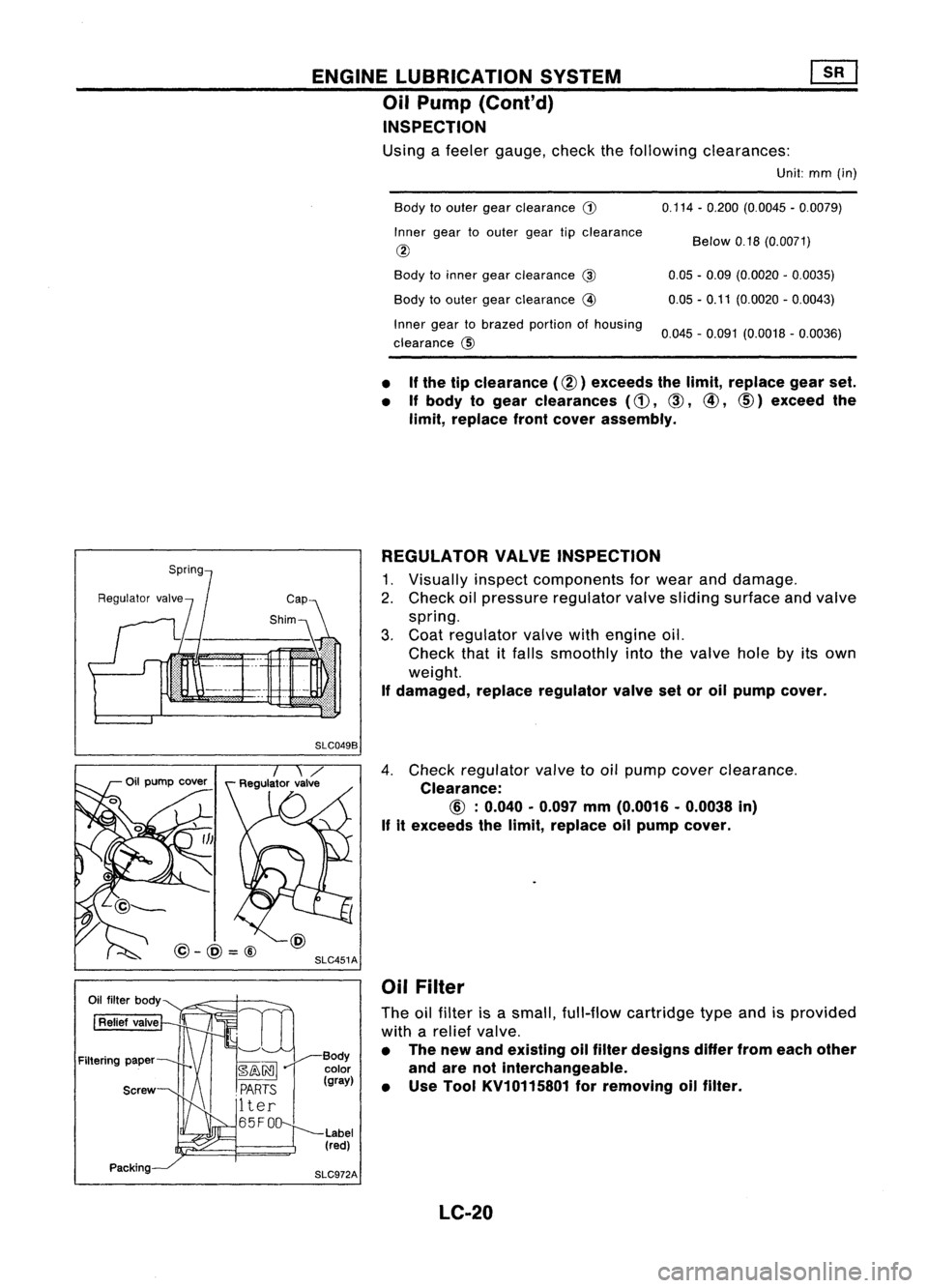
ENGINELUBRICATION SYSTEM
Oil Pump (Cont'd)
INSPECTION
Using afeeler gauge, checkthefollowing clearances:
Unit:mm(in)
Body toouter gearclearance
G)
Inner geartoouter geartipclearance
@
Body toinner gearclearance
@
Body toouter gearclearance
@
Inner geartobrazed portionofhousing
clearance @ 0.114
-0.200 (0.0045 -0.0079)
Below 0.18(0.0071)
0.05 -0.09 (0.0020 -0.0035)
0.05 -0.11 (0.0020 -0.0043)
0.045 -0.091 (0.0018 -0.0036)
• If
the tipclearance (@) exceeds thelimit, replace gearset.
• Ifbody togear clearances
(d),
CID,
@,
CID)
exceed the
limit, replace frontcover assembly.
REGULATOR VALVEINSPECTION
1. Visually inspectcomponents forwear anddamage.
2. Check oilpressure regulator valvesliding surface andvalve
spring.
3. Coat regulator valvewithengine oil.
Check thatitfalls smoothly intothevalve holebyitsown
weight.
If damaged, replaceregulator valvesetoroil pump cover.
SLC049B
SLC451A
@-@=@
4.
Check regulator valvetooil pump cover clearance.
Clearance:
If
itexceeds thelimit, replace oilpump cover.
Oil Filter
The oilfilter isasmall, full-flow cartridge typeandisprovided
with arelief valve.
• The new andeXisting oilfilter designs differfromeach other
and arenotinterchangeable.
• Use Tool KV10115801 forremoving oilfilter.
LC-20
Page 1408 of 1701

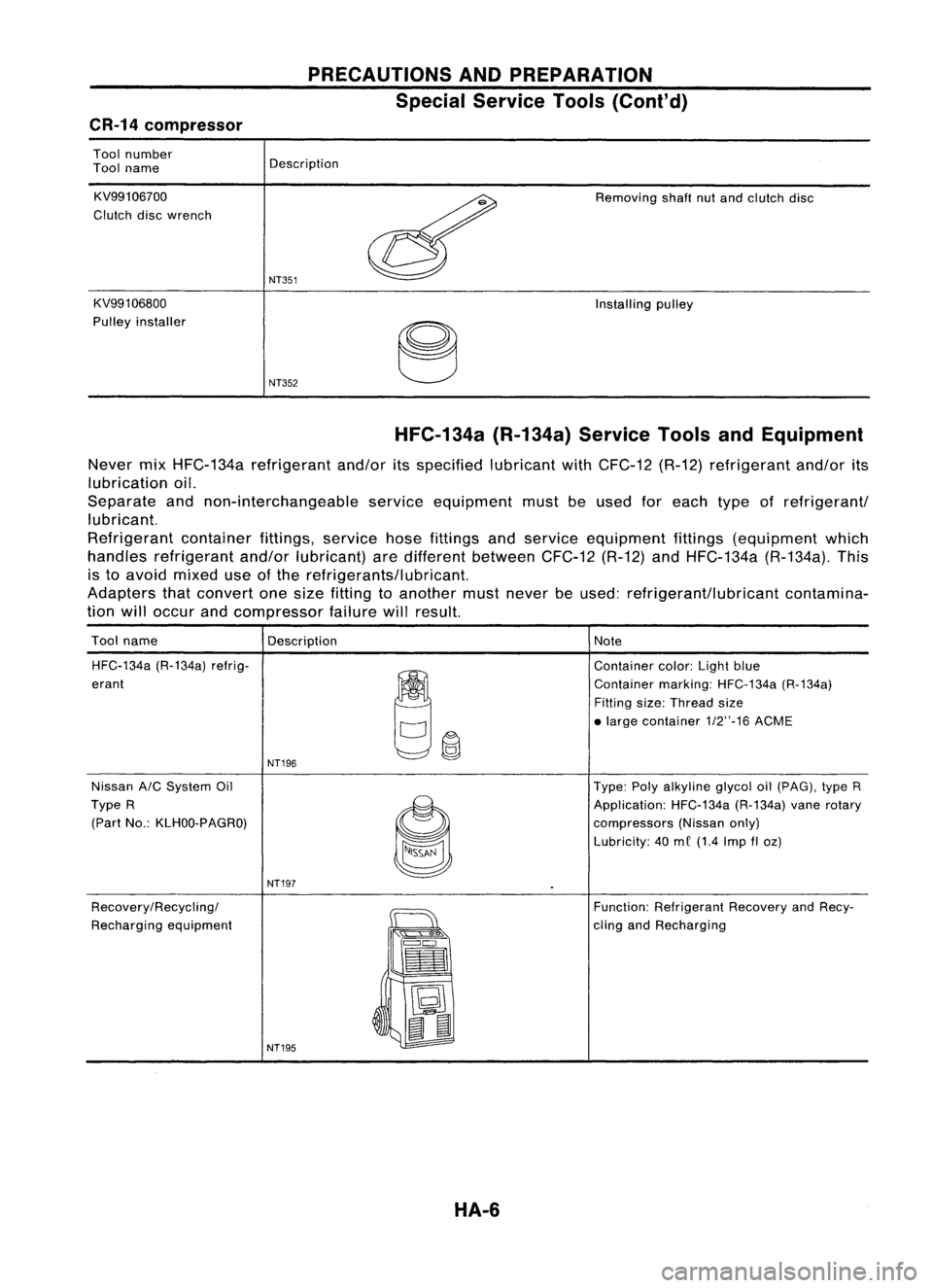
PRECAUTIONSANDPREPARATION
Special Service Tools(Cont'd)
CR-14 compressor
Tool number
Tool name
KV99106700
Clutch discwrench
KV991 06800
Pulley installer Description
NT351
NT352
Removing
shaftnutand clutch disc
Installing pulley
HFC-134a (R-134a)ServiceToolsandEquipment
Never mixHFC-134a refrigerant and/oritsspecified lubricantwithCFC-12 (R-12)refrigerant and/orits
lubrication oil.
Separate andnon-interchangeable serviceequipment mustbeused foreach typeofrefrigerant/
lubricant.
Refrigerant containerfittings,servicehosefittings andservice equipment fittings(equipment which
handles refrigerant and/orlubricant) aredifferent between CFC-12(R-12)andHFC-134a (R-134a).This
is to avoid mixed useofthe refrigerants/lubricant.
Adapters thatconvert onesize fitting toanother mustnever beused: refrigerant/lubricant contamina-
tion willoccur andcompressor failurewillresult.
Tool name
Description Note
HFC-134a (R-134a)refrig-
~~
Container
color:Lightblue
erant Containermarking:HFC-134a (R-134a)
Fitting size:Thread size
• large contai ner1/2"-16 ACME
NT196
Nissan A/CSystem Oil Type:Polyalkyline glycoloil(pAG), typeR
Type R
~
Application:
HFC-134a(R-134a)vanerotary
(Part No.:KLHOO-PAGRO)
compressors(Nissanonly)
Lubricity: 40me (1.4 Imp
fI
oz)
NT197
Recovery/Recycling/
~
Function:
Refrigerant RecoveryandRecy-
Recharging equipment
":'s
Q"'~
cling
andRecharging
==
•
~ t:J
~
II
NT195
HA-6