Page 271 of 1701
BRAKESYSTEM
SECTION
CONTENTS BR
PRECAUTIONS ANDPREPARATION
3
Precautions 3
Special Service Tools 4
Commercial ServiceTools 4
CHECK ANDADJUSTMENT 5
Checking BrakeFluidLevel 5
Checking BrakeLine 5
Changing BrakeFluid 5
AIR
BLEEDING 6
Bleeding Procedure 6
BRAKE HYDRAULIC LINE 7
Removal 8
Inspection 8
Installation 8
CONTROL VALVE 9
Proportioning Valve 9
BRAKE PEDALANDBRACKET 11
Removal andInstallation 11
Inspection 11
Adjustment 11
MASTER CYLINDER 12
Removal 12
Disassembly 12
Inspection 13
Assembly 13
Installation 14
BRAKE BOOSTER 15
On-vehicle Service 15
Removal 15
Inspection 16
Installation 16
VACUUM HOSE 17
Removal andInstallation 17
Inspection 17
FRONT DISCBRAKE 19
Pad Replacement.. 19
Removal 22
Disassembly 22Inspection
-Caliper 22
Inspection -Rotor 23
Assembly '".23
Installation 24
REAR DRUM BRAKE 25
Removal 25
Inspection -Wheel Cylinder 26
Wheel Cylinder Overhaul 27
Inspection -Drum 27
Inspection -Lining 27
Installation 27
REAR DISCBRAKE 29
Pad Replacement 29
~~s:~::~'~I~':::::::::::'::: ::.::::::::.::::::.::::::::::.::::::.::::::::~~ •••
Inspection -Caliper 32
Inspection -Rotor 33
Assembly 33
Installation 35
PARKING BRAKECONTROL 36
Removal andInstallation 36
Inspection 36
Adjustment ." 37
ANTI-LOCK BRAKESYSTEM 38
Purpose 38
Operation 38
ABS Hydraulic Circuit 38
System Components 39
System Description 39
Removal andInstallation .40
Wiring Diagram -ABS - .45
TROUBLE DIAGNOSES
52
Contents 52
Component PartsandHarness Connector
Location 64
SERVICE DATAANDSPECIFICATIONS (SDS)86
General Specifications 86
Inspection andAdjustment 88
Page 274 of 1701
GG94310000or
commercial equivalent
SBR820BA
For
tightening flarenut
Tool number
Tool name
PRECAUTIONS
ANDPREPARATION
Precautions (Conl'd)
BRAKE SYSTEM
• Recommended fluidisbrake fluid"DOT 3"or"DOT 4".
• Never reusedrained brakefluid.
• Donot mix different typesofbrake fluids (DOT3,DOT 4).
• Becareful nottosplash brakefluidonpainted areas;itmay
cause paintdamage. Ifbrake fluidissplashed onpainted
areas, washitaway withwater immediately.
• Toclean master cylinder parts,discbrake caliper partsor
wheel cylinder parts,useclean brake fluid.
• Never usemineral oilssuch asgasoline orkerosene. They
will ruin rubber partsofhydraulic system.
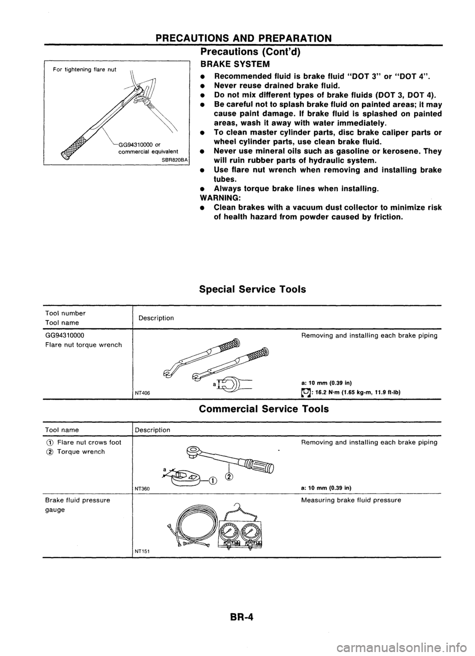
• Use flare nutwrench whenremoving andinstalling brake
tubes.
• Always torquebrakelineswhen installing.
WARNING:
• Clean brakes withavacuum dustcollector tominimize risk
of health hazard frompowder causedbyfriction.
Special Service Tools
Description
GG9431 0000
Flare nuttorque wrench
NT406
Removing
andinstalling eachbrake piping
a: 10 mm (0.39 in)
~: 16.2N'm(1.65 kg-m, 11.9f1-lb)
Commercial ServiceTools
Description
Tool name
CD
Flare nutcrows foot
@ Torque wrench
Brake fluidpressure
gauge
NT360
NT151
Removing
andinstalling eachbrake piping
a: 10 mm (0.39 in)
Measuring brakefluidpressure
BR-4
Page 275 of 1701
CHECKANDADJUSTMENT
OK
MINMax.
line
Min. line
SBR418C
Checking
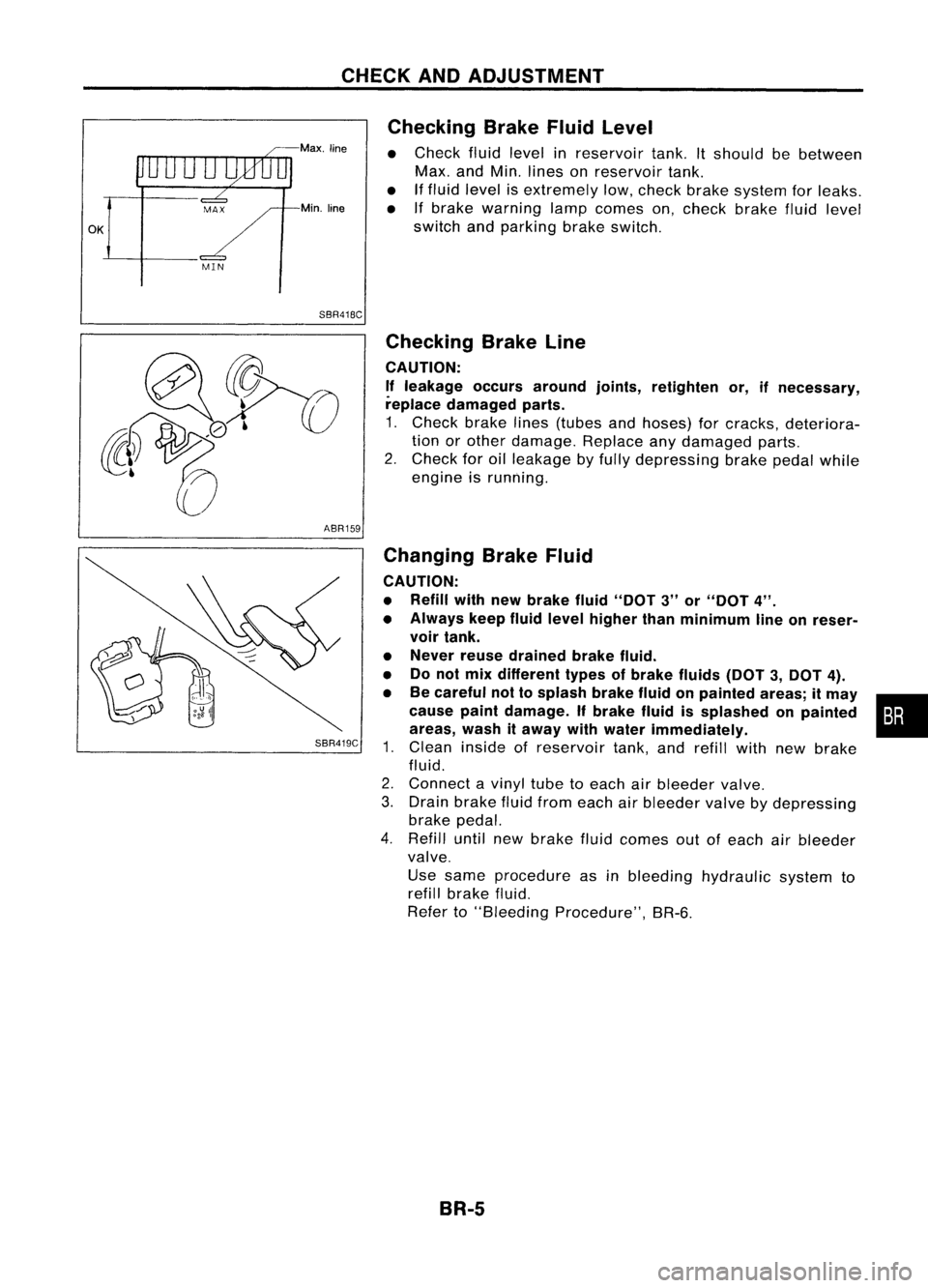
BrakeFluidLevel
• Check fluidlevel inreservoir tank.Itshould bebetween
Max. andMin. lines onreservoir tank.
• Iffluid level isextremely low,check brakesystem forleaks.
• Ifbrake warning lampcomes on,check brakefluidlevel
switch andparking brakeswitch.
ABR159
SBR419C
Checking
BrakeLine
CAUTION: If leakage occursaround joints,retighten or,ifnecessary,
replace damaged parts.
1. Check brakelines(tubes andhoses) forcracks, deteriora-
tion orother damage. Replaceanydamaged parts.
2. Check foroilleakage byfully depressing brakepedalwhile
engine isrunning.
Changing BrakeFluid
CAUTION:
• Refill withnewbrake fluid"DOT 3"or"DOT 4".
• Always keepfluidlevel higher thanminimum lineonreser-
voir tank.
• Never reusedrained brakefluid.
• Donot mix different typesofbrake fluids(DOT3,DOT 4).
• Becareful nottosplash brakefluidonpainted areas;itmay •
cause paintdamage. Ifbrake fluidissplashed onpainted :•
areas, washitaway withwater immediately.
1. Clean inside ofreservoir tank,andrefill withnewbrake
fluid.
2. Connect avinyl tubetoeach airbleeder valve.
3. Drain brake fluidfrom each airbleeder valvebydepressing
brake pedal.
4. Refill untilnewbrake fluidcomes outofeach airbleeder
valve.
Use same procedure asinbleeding hydraulic systemto
refill brake fluid.
Refer to"Bleeding Procedure", BR-6.
BR-5
Page 278 of 1701
BRAKEHYDRAULIC LINE
SBR419C
For tightening flarenut
~GG94310000
or
commercial equivalent
SBR820BA
Removal
CAUTION: • Becareful nottosplash brakefluidonpainted areas;itmay
cause paintdamage. Ifbrake fluidissplashed onpainted
areas, washitaway withwater immediately.
• Allhoses mustbefree from excessive bending,tWistingand
pulling.
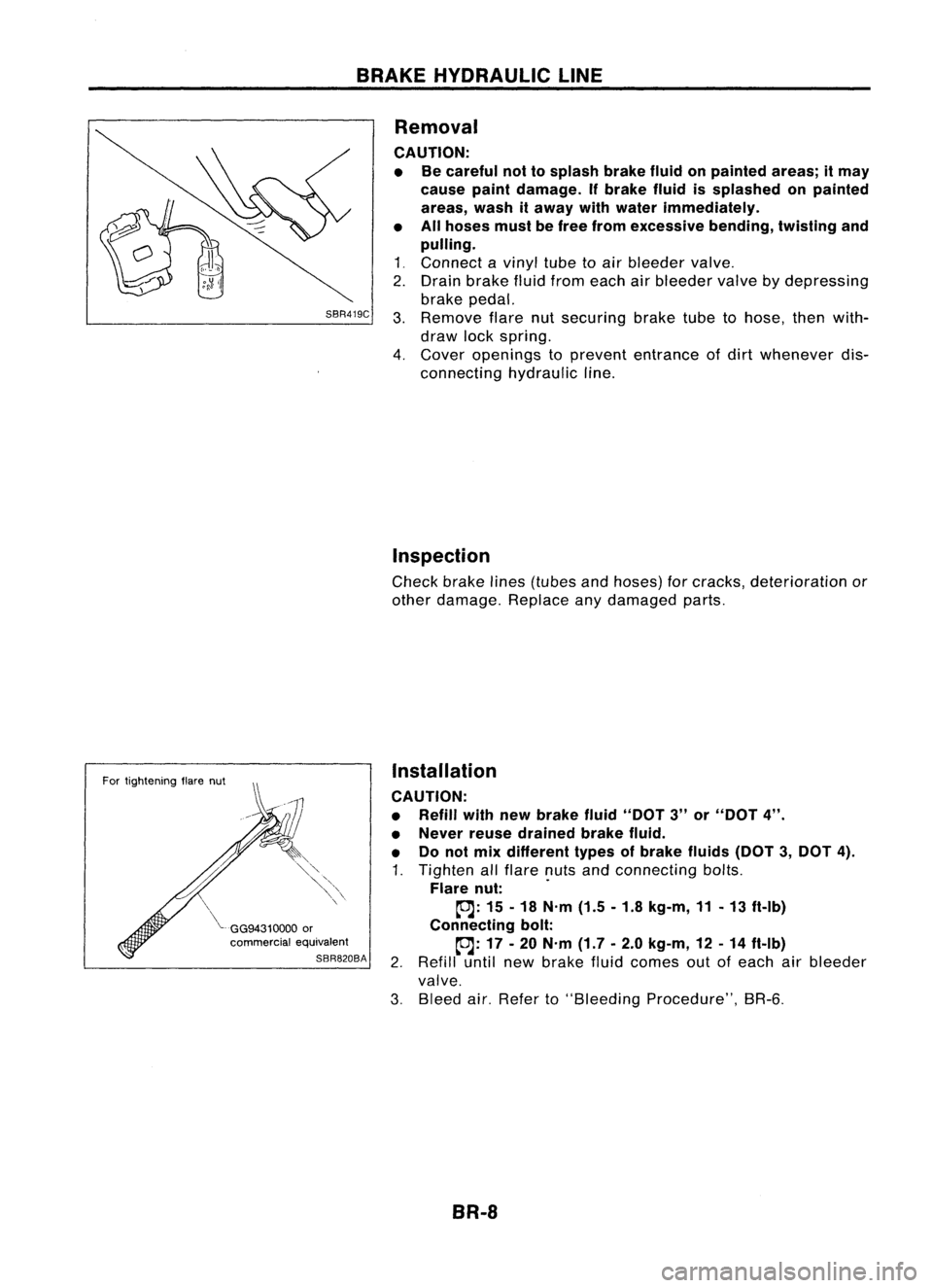
1 ~ Connect a
vinyl
tubetoair bleeder
valve~
2. Drain brake fluidfrom each airbleeder
valve
bydepressing
brake pedal.
3. Remove
flarenutsecuring braketubetohose, thenwith-
draw lockspring.
4. Cover
openings to
prevent
entrance ofdirt
whenever
dis-
connecting hydraulicline.
Inspection
Check brakelines(tubes andhoses) forcracks, deterioration or
other damage. Replaceanydamaged parts.
Installation
CAUTION:
• Refill withnewbrake fluid"DOT 3"or"DOT 4".
• Never reusedrained brakefluid.
• Donot mix different typesofbrake fluids(DOT3,DOT 4).
1. Tighten allflare nutsandconnecting bolts.
Flare nut: .
~: 15-18 N'm (1.5-1.8 kg-m, 11-13 ft-Ib)
Connecting bolt:
~: 17-20 N'm (1.7-2.0 kg-m, 12-14 ft-Ib)
2. Refill untilnewbrake fluidcomes outofeach airbleeder
valve.
3. Bleed air.Refer to"Bleeding Procedure", BR-6.
BR-8
Page 360 of 1701
PRECAUTIONSANDPREPARATION
Precautions
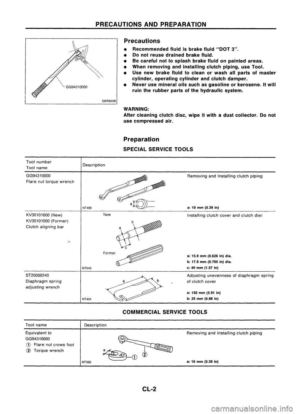
• Recommended fluidisbrake fluid"DOT 3".
• Donot reuse drained brakefluid.
• Becareful nottosplash brakefluidonpainted areas.
• When removing andinstalling clutchpiping, useTool.
• Use new brake fluidtoclean orwash allparts ofmaster
cylinder, operating cylinderandclutch damper.
• Never usemineral oilssuch asgasoline orkerosene. Itwill
ruin therubber partsofthe hydraulic system.
Tool number
Tool name
SBR820B
WARNING:
After cleaning clutchdisc,wipe itwith adust collector. Donot
use compressed air.
Preparation
SPECIAL SERVICE TOOLS
Description
New
GG94310000
Flare nuttorque wrench
KV30101600 (New)
KV30101000 (Former)
Clutch aligning bar
ST20050240 Diaphragm spring
adjusting wrench
NT406
NT645
NT404
Removing
andinstalling clutchpiping
a:
10
mm
(0.39
in)
Installing clutchcoverandclutch disc:
a:
15.9
mm
(0.626 In)dia.
b: 17.9 mm(0.705 in)dia.
c: 40 mm (1.57 in)
Adjusting unevenness ofdiaphragm spring
of clutch cover
a: 150 mm (5.91 in)
b: 25
mm
(0.98
in)
Tool name
Description
COMMERCIAL
SERVICETOOLS
Equivalent to
GG9431 0000
CD
Flare nutcrows foot
@
Torque wrench
NT360
Removing
andinstalling clutchpiping
a: 10 mm (0.39 in)
CL-2
Page 363 of 1701
INSPECTIONANDADJUSTMENT
Pedal stopper
Dash lower
panel (except
CD20 engine //
model)
/L
Floor car-pet
L
Dash reinforcement panel
(CD20 engine model)
Adjusting
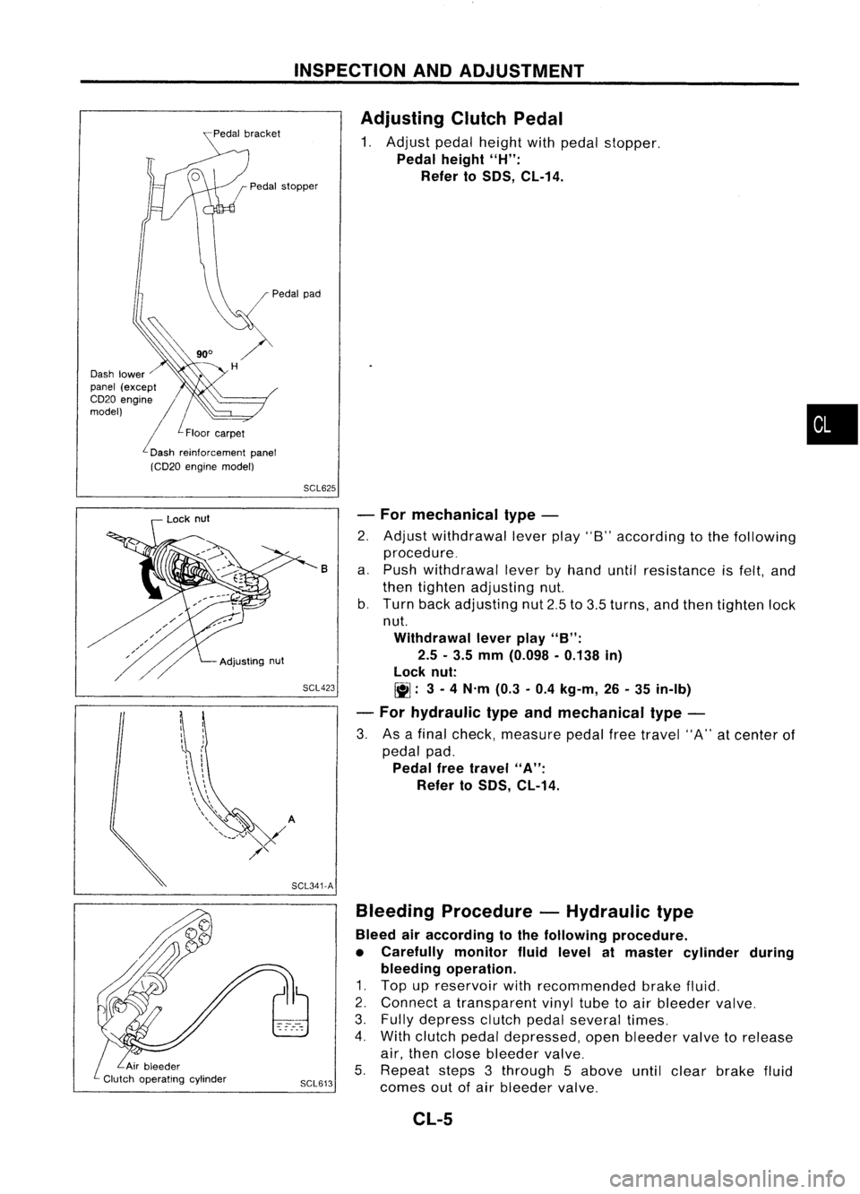
ClutchPedal
1. Adjust pedalheight withpedal stopper.
Pedal height
"H":
Refer to
50S,
CL-14.
•
SCL625
SCL423 -
For mechanical type-
2. Adjust withdrawal leverplay"8"according tothe following
procedure_
a. Push withdrawal leverbyhand untilresistance isfelt, and
then tighten adjusting nut.
b. Turn backadjusting nut2.5to3.5 turns, andthen tighten lock
nut.
Withdrawal leverplay
"B":
2.5 -3.5 mm (0.098 -0.138 in)
lock nut:
~: 3-
4 N'm (0.3-0.4 kg-m, 26-35 in-Ib)
- For hydraulic typeandmechanical type-
3. Asafinal check, measure pedalfreetravel "A"atcenter of
pedal pad.
Pedal freetravel
"A":
Refer to
50S,
CL-14.
B
Bleeding Procedure -Hydraulic type
Bleed airaccording tothe following procedure.
• Carefully monitorfluidlevel atmaster cylinder during
bleeding operation.
1. Top upreservoir withrecommended brakefluid.
2. Connect atransparent vinyltubetoair bleeder valve.
3. Fully depress clutchpedalseveral times.
4. With clutch pedaldepressed, openbleeder valvetorelease
air, then close bleeder valve.
5. Repeat steps3through 5above untilclear brake fluid
SCL613
comesoutofair bleeder valve.
SCL341-A
Adjusting
nut
Lock
nut
CL-5
Page 364 of 1701
HYDRAULICCLUTCHCONTROL
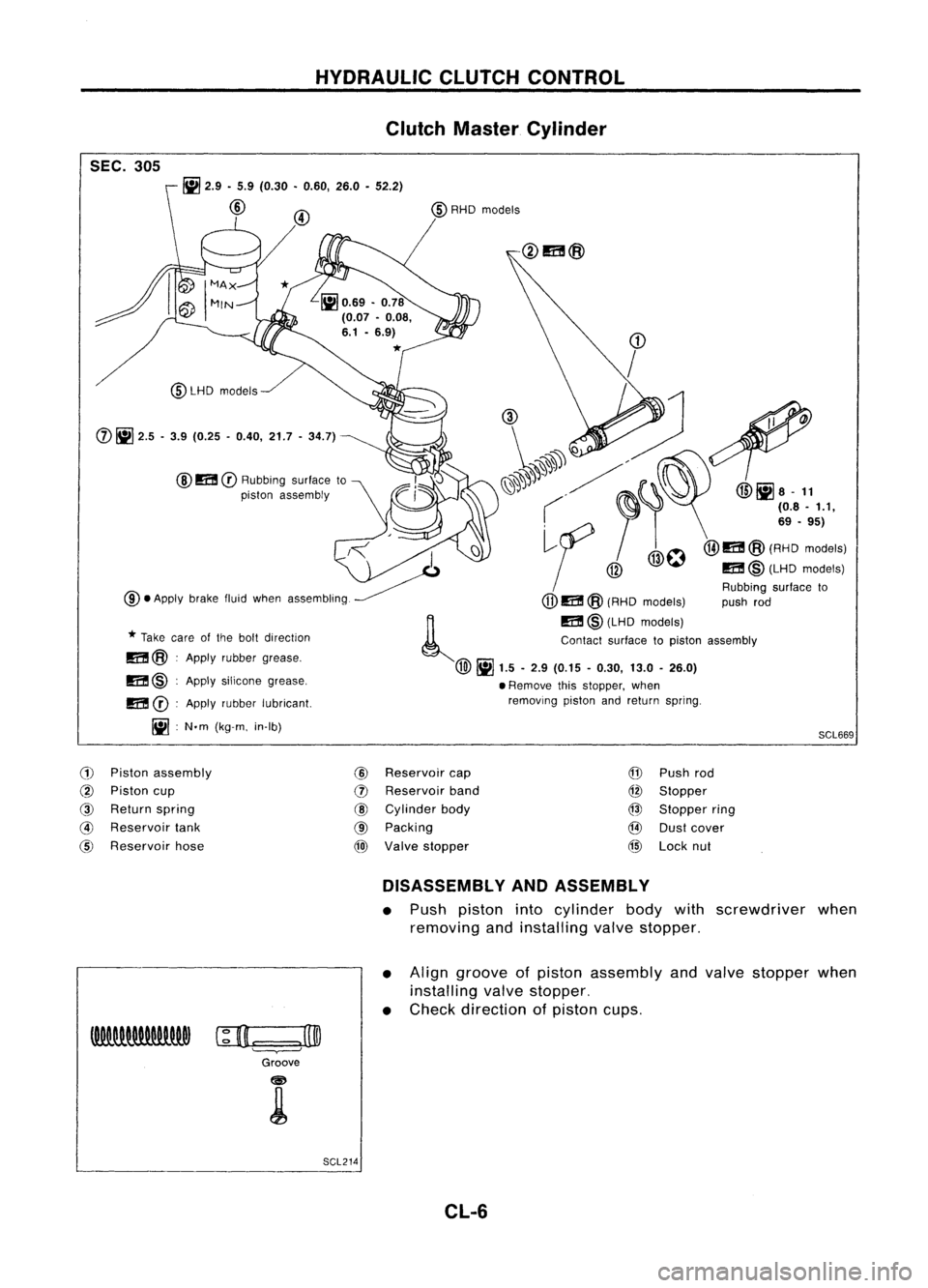
Clutch Master Cylinder
SEC. 305
SCL669
~
2.9 •5.9 (0.30 •0.60, 26.0•52.2)
@
@
m
CD
Rubbing surfaceto
piston assembly
@LHD
models
m @:Apply silicone grease,
m
CD:
Apply rubber lubricant.
Iil :
N.m (kg-m. in-Ib)
CD
/
(1), ~
1'.
~'. ~". @liJa-
11
( ~I'
(08.'.1,
,<
I
~f
/@O@I1I!@(A':o'::"'1
~ @
m@(LHDmodels)
Rubbing surfaceto
@.
Apply brakefluidwhen assembling.
(jJ)
m @(RHD models) pushrod
~ m@(LHD models)
*
Take careofthe bolt direction Contactsurfacetopiston assembly
m@ :Apply rubber grease.
@~
1.5-2.9 (0.15 -0.30, 13.0-26.0)
• Remove thisstopper, when
removing pistonandreturn spring.
(j)
~
2.5 -3.9 (0.25 -0.40, 21.7-34.7)
(1)
Piston assembly
@
Reservoir
cap
@
Piston cup
(])
Reservoir
band
@
Return spring
@
Cylinder body
@
Reservoir
tank
@
Packing
@
Reservoir hose
@)
Valve stopper
@
Push rod
@
Stopper
@
Stopper ring
@
Dustcover
@
Lock nut
DISASSEMBLY ANDASSEMBLY
• Push piston intocylinder bodywithscrewdriver when
removing andinstalling valvestopper.
• Align groove ofpiston assembly andvalve stopper when
installing valvestopper.
• Check direction ofpiston cups.
c;D.=:
=.J3@
Groove
SCL214 CL-6
Page 1531 of 1701
CHASSISANDBODY MAINTENANCE
Checking ExhaustSystem
Check exhaust pipes,muffler andmounting forimproper attach-
ment andforleaks, cracks, damage, looseconnections, chafing
and deterioration. •
SMA211A Checking ClutchFluidLevel andLeaks
If fluid level isextremely low,check clutch system forleaks.
SMA449C Checking ClutchSystem
HYDRAULIC TYPE
Check fluidlines andoperating cylinderforimproper
attachment, cracks,damage, looseconnections, chafingand
deterioration.
jJ
I
SMA"",
MECHANICAL TYPE
Check cableandlinks forimproper attachment, chafing,wear
and deterioration.
SMA141A Checking MITOil
• Check thatoilisnot leaking fromtransaxle oraround it.
• Remove speedometer pinionandcheck thattheoillevel L
at vehicle rearside iswithin specification.
Specified
Specifiedoillevel (Dimension L):
oil level
RS5F30A58-66 mm (2.28 -2.60 in)
RS5F31A GA engine 57-66 mm (2.24 -2.60 in)
CD engine 54-61 mm (2.13 -2.40 in)
RS5F32A 39-44 mm (1.54 -1.73 in)
SMT512C
MA-45