1995 NISSAN ALMERA N15 battery location
[x] Cancel search: battery locationPage 323 of 1701
.=J
MPH
-~s::~
~~
___ --- warnin:1
TROUBLE
DIAGNOSES
Self-diagnosis (ForEurope)
FUNCTION
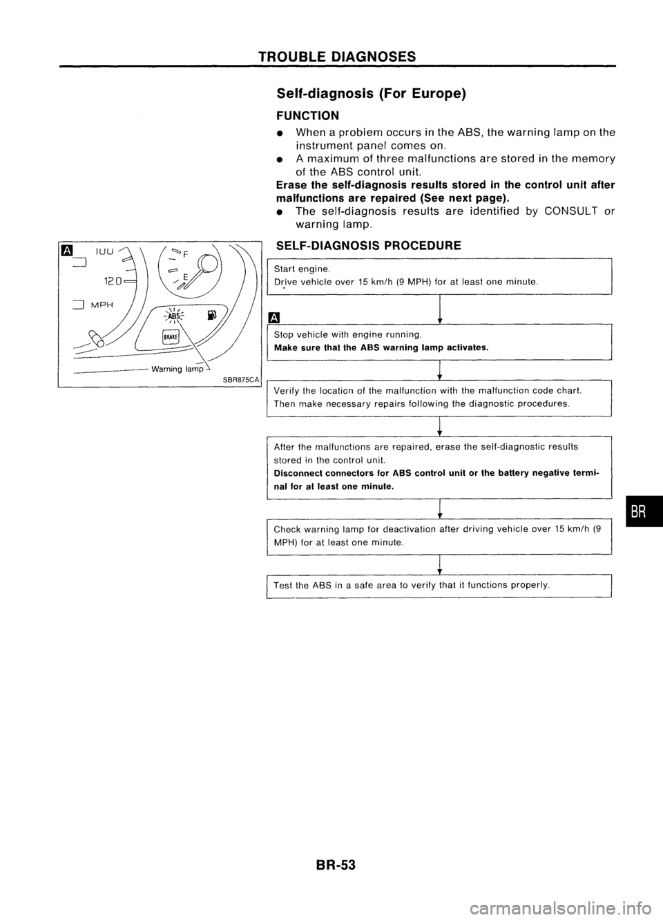
• When aproblem occursinthe ABS, thewarning lamponthe
instrument panelcomes on.
• Amaximum ofthree malfunctions arestored inthe memory
of the ABS control unit.
Erase theself-diagnosis resultsstoredinthe control unitafter
malfunctions arerepaired (Seenextpage).
• The self-diagnosis resultsareidentified byCONSULT or
warning lamp.
SELF-DIAGNOSIS PROCEDURE
Start engine.
Dr.ive vehicle over15km/h (9MPH) foratleast oneminute .
Stop vehicle withengine running.
Make surethaitheASS warning lampactivates.
SBR875CA
Verifythelocation ofthe malfunction withthemalfunction codechart.
Then make necessary repairsfollowing thediagnostic procedures.
After themalfunctions arerepaired, erasetheself-diagnostic results
stored inthe control unit.
Disconnect connectors forASS control unitorthe battery negative termi-
nal foratleast oneminute.
Check warning lampfordeactivation afterdriving vehicle over15km/h (9
MPH) foratleast oneminute.
Test theASS inasafe area toverify thatitfunctions properly.
BR-53
•
Page 569 of 1701
POWERWINDOW
Trouble Diagnoses
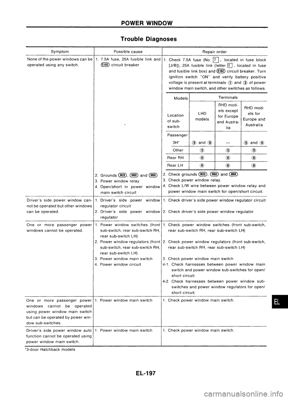
None ofthe power windows canbe1.7.5A fuse, 25Afusible linkand 1.
operated usinganyswitch. ~circuit breaker
Symptom
Possiblecause
Repairorder
Check 7.5Afuse(No.
12J,
located infuse block
[J/B)), 25Afusible link(letter [[],located infuse
and fusible linkbox) and~ circuit breaker. Turn
ignition switch"ON"andverify battery positive
voltage ispresent atterminals
CD
and @ofpower
window mainswitch, andother switches asfollows.
Models Terminals
Location
of sub-
switch LHD
models RHD
mod-
els except
for Europe
and Austra-
lia RHD
mod-
els for
Europe and
Australia
Passenger 3H*
@
and @
-
@
and @
Other
@@
@
Rear RH @
@
@
Rear LH @
@@
Check grounds
@,~
and
@ill.
Check powerwindow relay.
Check LlWwire between powerwindow relayand
power window mainswitch foropen/short circuit.
2.
3.
window 4.
2.
Grounds
@,~
and
@ill
3. Power window relay
4. Open/short inpower
main switch circuit
Driver's sidepower window can-1.Driver's sidepower window 1.Check driver's sidepower window regulator circuit
not beoperated butother windows regulatorcircuit
can beoperated. 2.Driver's sidepower window 2.Check driver's sidepower window regulator
regulator
•
1.
Check powerwindow switches (frontsub-switch,
rear sub-switch RH,rear sub-switch LH)
2. Check power window regulators (frontsub-switch,
rear sub-switch RH,rear sub-switch LH)
3. Check powerwindow mainswitch
4-1. Check harnesses betweenpowerwindow main
switch andpower window sub-switches foropen/
short circuit.
4-2. Check harnesses betweenpowerwindow sub-
switches andpower window regulators foropen/
short circuit.
1. Check powerwindow mainswitch.
Power
window switches (front
sub-switch, rearsub-switch RH,
rear sub-switch LH)
2. Power window regulators (front
sub-switch, rearsub-switch RH,
rear sub-switch LH)
3. Power window mainswitch
4. Power window circuit
One
ormore passenger power1.
windows cannotbeoperated.
One ormore passenger power1.Power window mainswitch
windows cannotbeoperated
using power window mainswitch
but can beoperated bypower win-
dow sub-switches.
Driver's sidepower window auto1.Power window mainswitch
function cannotbeoperated using
power window mainswitch. 1.
Check powerwindow mainswitch.
*3-door Hatchback models
EL-197
Page 727 of 1701
PRECAUTIONSANDPREPARATION
Engine Fuel
&
Emission ControlSystem
I
GA, SR
I
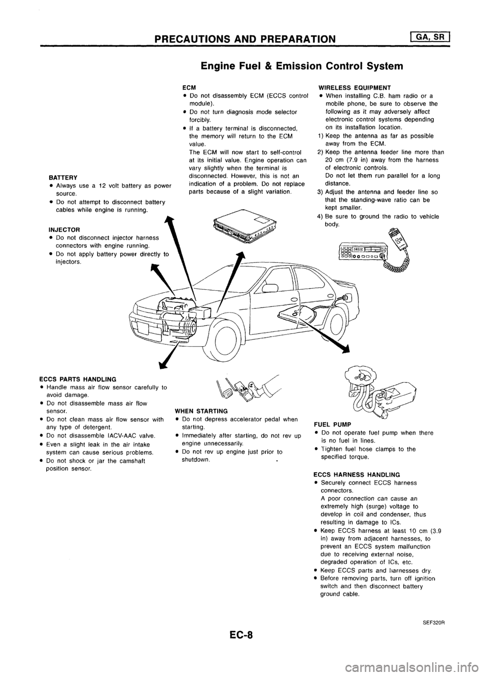
BATTERY • Always usea12 volt battery aspower
source.
• Do not attempt todisconnect battery
cables whileengine isrunning.
INJECTOR • Do not disconnect injectorharness
connectors withengine running.
• Do not apply battery powerdirectly to
injectors.
ECCS PARTS HANDLING
• Handle massairflow sensor carefully to
avoid damage.
• Do not disassemble massairflow
sensor.
• Do not clean massairflow sensor with
any type ofdetergent.
• Do not disassemble IACV-AACvalve.
• Even aslight leakinthe airintake
system cancause serious problems.
• Do not shock orjar the camshaft
position sensor. ECM
• Do not disassembly EGM(EGGS control
module).
• Do not turn diagnosis modeselector
forcibly.
• Ifabattery terminal isdisconnected,
the memory willreturn tothe ECM
value.
The ECM willnow start toself-control
at its initial value. Engine operation can
vary slightly whentheterminal is
disconnected. However,thisisnot an
indication ofaproblem. Donot replace
parts because ofaslight variation.
WHEN STARTING
• Do not depress accelerator pedalwhen
starting.
• Immediately afterstarting, donot revup
engine unnecessarily .
• Do not revupengine justprior to
shutdown.
EC-8 WIRELESS
EQUIPMENT
• When installing C.B.hamradio ora
mobile phone, besure toobserve the
following asitmay adversely affect
electronic controlsystems depending
on itsinstallation location.
1) Keep theantenna asfar aspossible
away fromtheEGM.
2) Keep theantenna feederlinemore than
20 em (7.9 in)away fromtheharness
of electronic controls.
Do not letthem runparallel foralong
distance.
3) Adjust theantenna andfeeder lineso
that thestanding-wave ratiocanbe
kept smaller.
4) Be sure toground theradio tovehicle
body.
FUEL PUMP
• Do not operate fuelpump whenthere
is no fuel inlines.
• Tighten fuelhose clamps tothe
specified torque.
ECCS HARNESS HANDLING
• Securely connectEGGSharness
connectors.
A poor connection cancause an
extremely high(surge) voltage to
develop incoil and condenser, thus
resulting indamage toICs .
• Keep ECGS harness atleast 10em (3.9
in) away fromadjacent harnesses, to
prevent anEGGS system malfunction
due toreceiving externalnoise,
degraded operation ofIGs, etc.
• Keep EGCS partsandharnesses dry.
• Before removing parts,turnoffignition
switch andthen disconnect battery
ground cable.
SEF320R
Page 1358 of 1701
SEF289HSGI233
SGI234 PRECAUTIONS
General Precautions (Cont'd)
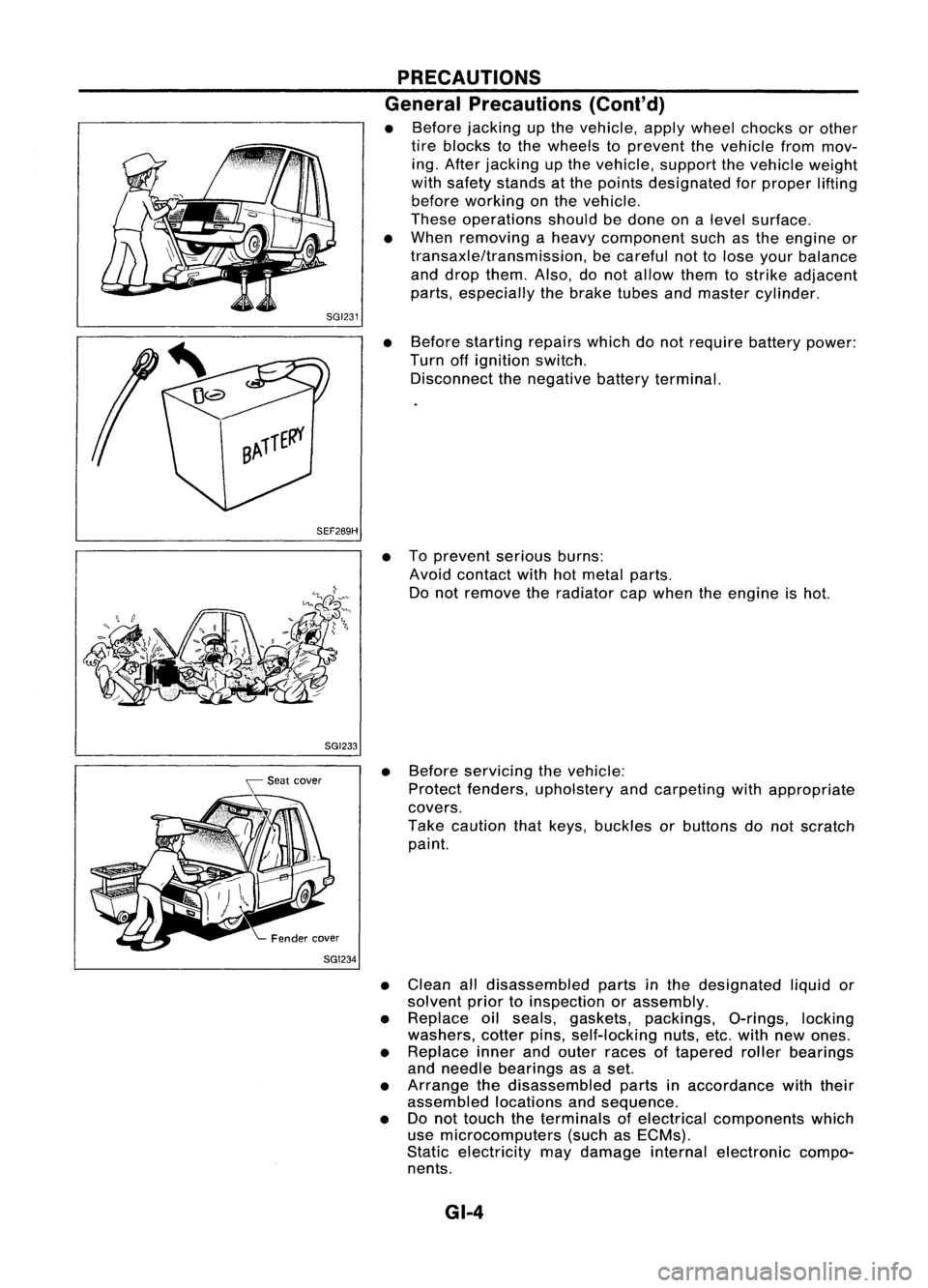
• Before jacking upthe vehicle, applywheel chocks orother
tire blocks tothe wheels toprevent thevehicle frommov-
ing. After jacking upthe vehicle, supportthevehicle weight
with safety stands atthe points designated forproper lifting
before working onthe vehicle.
These operations shouldbedone onalevel surface.
• When removing aheavy component suchasthe engine or
transaxle/transmission, becareful nottolose your balance
and drop them. Also,donot allow themtostrike adjacent
parts, especially thebrake tubesandmaster cylinder.
• Before starting repairswhichdonot require batterypower:
Turn offignition switch.
Disconnect thenegative batteryterminal.
• Toprevent seriousburns:
Avoid contact withhotmetal parts.
Do not remove theradiator capwhen theengine ishot.
• Before servicing thevehicle:
Protect fenders, upholstery andcarpeting withappropriate
covers.
Take caution thatkeys, buckles orbuttons donot scratch
paint.
• Clean alldisassembled partsinthe designated liquidor
solvent priortoinspection orassembly.
• Replace oilseals, gaskets, packings, O-rings,locking
washers, cotterpins,self-locking nuts,etc.with newones.
• Replace innerandouter races oftapered rollerbearings
and needle bearings asaset.
• Arrange thedisassembled partsinaccordance withtheir
assembled locationsandsequence.
• Donot touch theterminals ofelectrical components which
use microcomputers (suchasECMs).
Static electricity maydamage internalelectronic compo-
nents.
GI-4
Page 1365 of 1701
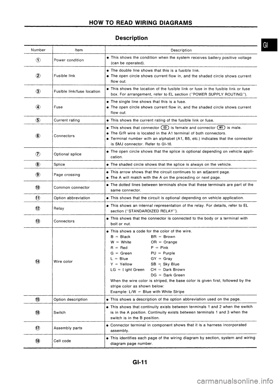
HOWTOREAD WIRING DIAGRAMS
Description
Number Item Description
CD
Power
condition •
This shows thecondition whenthesystem receives batterypositive voltage
(can beoperated) .
• The double lineshows thatthisisafusible link.
@
Fusiblelink
•The open circle shows current flowin,and theshaded circleshows current
flow out.
link/fuse location •
This shows thelocation ofthe fusible linkorfuse inthe fusible linkorfuse
box. Forarrangement, refertoEL section ("POWER SUPPLYROUTING") .
• The single lineshows thatthisisafuse.
@
Fuse
•The open circle shows current flowin,and theshaded circleshows current
flow out.
CID
Current
rating
•This shows thecurrent ratingofthe fusible linkorfuse .
• This shows thatconnector
@)
isfemale andconnector
@
ismale .
@
Connectors •
The G/R wire islocated inthe A1 terminal ofboth connectors.
• Terminal numberwithanalphabet (A1, B5, etc.) indicates thattheconnector
is SMJ connector. RefertoGI-16 .
rJ)
Optionalsplice •
The open circle shows thatthesplice isoptional depending onvehicle appli-
cation.
@
Splice •The shaded circleshows thatthesplice isalways onthe vehicle.
@
Page
crossing •
This arrow shows thatthecircuit continues toan adjacent page.
• The Awill match withtheAon the preceding ornext page .
@)
Commonconnector •
The dotted linesbetween terminals showthatthese terminals arepart ofthe
same connector.
@
Option
abbreviation •This shows thatthecircuit isoptional depending onvehicle application.
@
Relay •
This shows aninternal representation ofthe relay. Fordetails, refertoEL
section ("STANDARDIZED RELAY").
@
Connectors •
This shows thattheconnector isconnected tothe body oraterminal with
bolt ornut.
• This shows acode forthe color ofthe wire.
B
=
Black BR
=
Brown
W
=
White OR
=
Orange
R
=
Red P
=
Pink
G
=
Green PU
=
Purple
@
Wire
color L
=
Blue GY
=
Gray
Y
=
Yellow SB
=:
Sky Blue
LG
=
Light Green CH
=
Dark Brown
DG
=
Dark Green
When thewire color isstriped, thebase color isgiven first,followed bythe
stripe colorasshown below:
Example: LlW
=
Blue withWhite Stripe
@
Optiondescription •
This shows adescription ofthe option abbreviation usedonthe page.
• This shows thatcontinuity existsbetween terminals 1and 2when theswitch
@)
Switch is
inthe Aposition. Continuity existsbetween terminals 1and 3when the
switch isinthe Bposition .
@
Assembly
parts •
Connector terminalincomponent showsthatitis aharness incorporated
assembly .
@
Cell
code •
This identifies eachpage ofthe wiring diagram bysection, systemandwiring
diagram pagenumber.
GI-11
•
Page 1383 of 1701
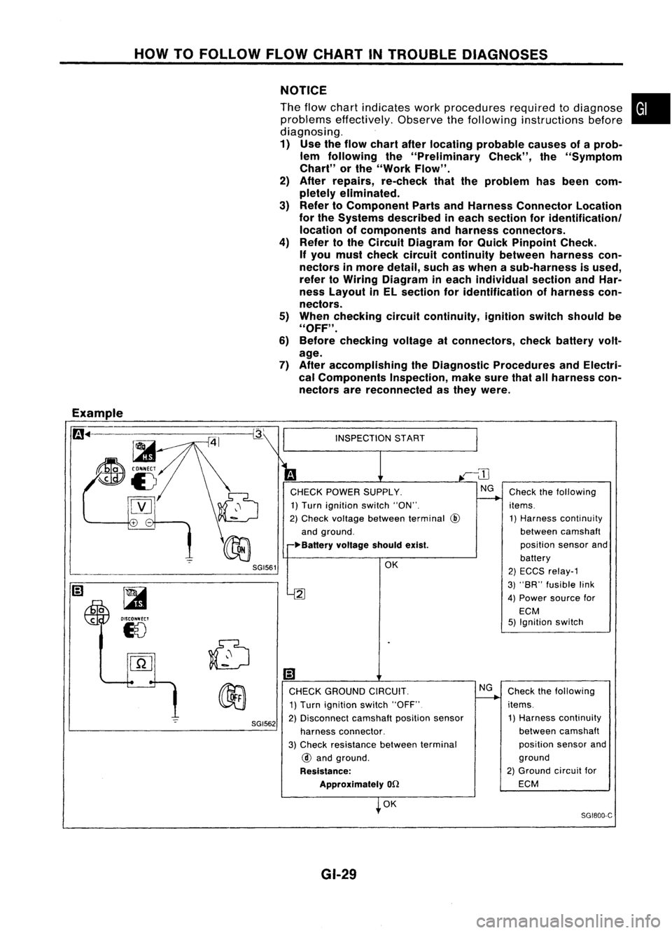
HOWTOFOLLOW FLOWCHART INTROUBLE DIAGNOSES
NOTICE
The flow chart indicates workprocedures requiredtodiagnose
problems effectively. Observethefollowing instructions before
diagnosing.
1) Use theflow chart afterlocating probable causesofaprob-
lem following the"Preliminary Check",the"Symptom
Chart" orthe "Work Flow".
2) After repairs, re-check thattheproblem hasbeen com-
pletely eliminated.
3) Refer toComponent PartsandHarness Connector Location
for the Systems described ineach section foridentificationl
location ofcomponents andharness connectors.
4) Refer tothe Circuit Diagram forQuick Pinpoint Check.
If you must check circuit continuity betweenharnesscon-
nectors inmore detail, suchaswhen asub-harness isused,
refer toWiring Diagram ineach individual sectionandHar-
ness Layout inEL section foridentification ofharness con-
nectors.
5) When checking circuitcontinuity, ignitionswitchshould be
"OFF" .
6) Before checking voltageatconnectors, checkbattery volt-
age.
7) After accomplishing theDiagnostic Procedures andElectri-
cal Components Inspection,makesurethatallharness con-
nectors arereconnected asthey were.
•
Example
m ..
-=-=~-----------~
~
~i5
[YJ
SGI561
~
OISCONNECT
18
SGI562
INSPECTION
START
CHECK POWER SUPPLY.
1) Turn ignition switch"ON".
2) Check voltage between terminal
@
and ground.
~Ba"ery voltageshouldexist.
OK
2
Ii)
CHECK GROUND CIRCUIT.
1) Turn ignition switch"OFF"
2) Disconnect camshaftpositionsensor
harness connector.
3) Check resistance betweenterminal
@
and ground.
Resistance: Approximately
on
OK
GI-29 NG
Check
thefollowing
items. 1) Harness continuity
between camshaft
position sensorand
battery
2) ECCS relay-1
3) "SR" fusible link
4) Power source for
ECM
5) Ignition switch
Check thefollowing
items. 1) Harness continuity
between camshaft
position sensorand
ground
2) Ground circuitfor
ECM
SG1800-C