Page 14 of 1701

DESCRIPTION
Shift Mechanism
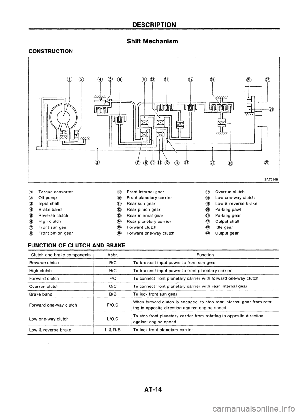
CONSTRUCTION
18
,:-1
SAT214H
ill
Torque converter
@
Oilpump
@
Input shaft
@
Brake band
@
Reverse clutch
@
High clutch
o
Front sungear
@
Front pinion gear
@
Front internal gear
@l
Front planetary carrier
@
Rear sungear
@
Rear pinion gear
@
Rear internal gear
@
Rear planetary carrier
@
Forward clutch
@
Forward one-way clutch
@
Overrun clutch
@
Lowone-way clutch
@
Low
&
reverse brake
@
Parking pawl
@
Parking gear
@
Output shaft
@
Idlegear
@
Output gear
FUNCTION OFCLUTCH ANDBRAKE
Glutch andbrake components Abbr. Function
Reverse clutch
RIG
To
transmit inputpower tofront sungear
High clutch
HIG
To
transmit inputpower tofront planetary carrier
Forward clutch
FIG
To
connect frontplanetary carrierwithforward one-way clutch
Overrun clutch
OIG
To
connect frontplanetary carrierwithrearinternal gear
Brake band BIBTo
lock front sungear
Forward one-way clutch
F/O.G
When
forward clutchisengaged, tostop rearinternai gearfrom rotat-
ing inopposite direction againstenginespeed
Low one-way clutch LlO.GTo
stop front planetary carrierfromrotating inopposite direction
against enginespeed
Low
&
reverse brake L
&
RIB To
lock front planetary carrier
AT-14
Page 18 of 1701

SAT497GTROUBLE
DIAGNOSES
Road Testing (Cont'd)
"0"
POSITION
1. Manually moveselector leverfrom"N"to"D" position, and
note shiftquality.
2. Using theshift schedule asareference, drivevehicle in"D"
position. Record,onsymptom chart,respective vehicle
speeds atwhich up-shifting anddown-shifting occur.These
speeds aretobe read atthree different throttlepositions
(light, halfandfull), respectively. Alsodetermine thetiming
at which shocks areencountered duringshifting andwhich
clutches areengaged.
SAT612GA
3.Determine whetherlock-upproperly occurswhiledriving
vehicle inproper gearposition andatproper vehicle speed.
4. Check todetermine ifshifting tooverdrive gearcannot be
made whileODcontrol switchis"OFF".
5. Drive vehicle in"D
3"
position athalf tolight throttle posi-
tion. Keep driving at60 to70 km/h (34to43 MPH). FUlly
depress accelerator pedaltomake suretransaxle down-
shifts from3rdto2nd gear.
6. Drive vehicle in"D
2"
position athalf tolight throttle posi-
tion. Keep driving at25 to35 km/h (16to22 MPH). Fully
depress accelerator pedaltomake suretransaxle down-
shifts from2ndto1st gear.
"2"
POSITION
1. Shift to"2" position andmake surevehicle startsin1st
gear.
2. Increase vehiclespeedtomake suretransaxle upshiftsfrom
1st to2nd gear.
3. Further increase vehiclespeed.Makesuretransaxle does
not upshift to3rd gear.
4. Drive vehicle in"2
2"
position athalf tolight throttle position.
Keep driving at25 to35 km/h (16to22 MPH). Fullydepress
accelerator pedaltomake suretransaxle downshifts from
2nd to1st gear.
5. Allow vehicle torun idle while in"2" position tomake sure
that transaxle downshifts to1st gear.
6. Move selector leverto"D" position andallow vehicle to
operate at30 to40 km/h (19to25 MPH). Then,shiftto"2"
position tomake suretransaxle downshifts to2nd gear.
"1"
POSITION
1. Place selector leverin"1" position andaccelerate vehicle.
Make suretransaxle doesnotshift from 1stto2nd gear
although vehiclespeedincreases.
2. Drive vehicle in"1" position. Releaseaccelerator pedalto
make surethatengine compression actsasabrake.
3. Place selector leverin"D" or"2" position andallow vehi-
cle torun at15 to25 km/h (9to 16 MPH). Thenmove selec-
tor lever to"1" position tomake suretransaxle downshifts
to 1st gear.
AT-18
Page 27 of 1701

'-)
(
~)o
Front
SAT498GTROUBLE
DIAGNOSES
Pressure Testing(Cont'd)
• Oilleakage ator around oilpump, control valvebody, trans-
mission caseorgovernor
• Sticking pressure regulator valve
• Sticking pressure modifiervalve
2) When linepressure whileidling islow ataparticular
position, checkthefollowing.
• Ifoil leaks ator around low
&
reverse brakecircuit, line
pressure becomes lowin"R" position. Butline pressure is
normal in"P", "D", "2"or"1" position.
3) When linepressure ishigh while idling, pressure regulator
valve mayhave stuck.
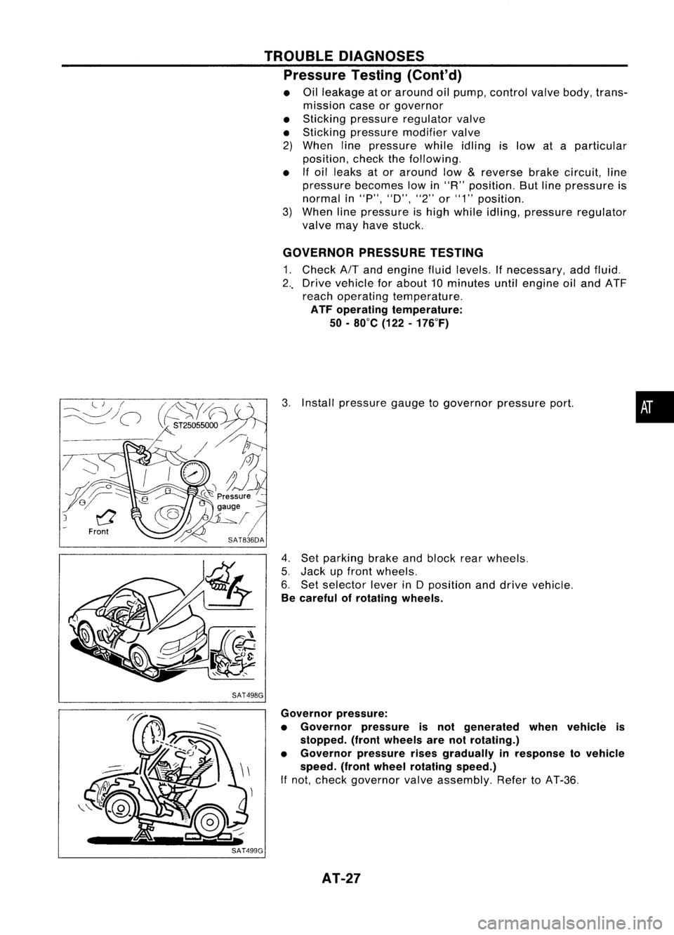
GOVERNOR PRESSURETESTING
1. Check
AIT
and engine fluidlevels. Ifnecessary, addfluid.
2 .. Drive vehicle forabout 10minutes untilengine oiland ATF
reach operating temperature.
ATF operating temperature:
50 -80°C (122-176°F)
3. Install pressure gaugetogovernor pressureport.
4. Set parking brakeandblock rearwheels.
5. Jack upfront wheels.
6. Set selector leverinDposition anddrive vehicle.
Be careful ofrotating wheels.
•
Governor pressure:
• Governor pressureisnot generated whenvehicle is
stopped. (frontwheels arenotrotating.)
• Governor pressurerisesgradually inresponse tovehicle
speed. (frontwheel rotating speed.)
If not, check governor valveassembly. RefertoAT-36.
AT-27
Page 34 of 1701

(atP,)
p,
(Full throttle position)
~ThrOttle drum
Direction U
, ,-- p,
t
I ~.
(Idling
--r ~_ .)
position)
I
Direction T
Engine side"
bracket (at
P,)
~ Adjusting tube
Lock plate ON-VEHICLE
SERVICE
Throttle WireAdjustment (Cont'd)
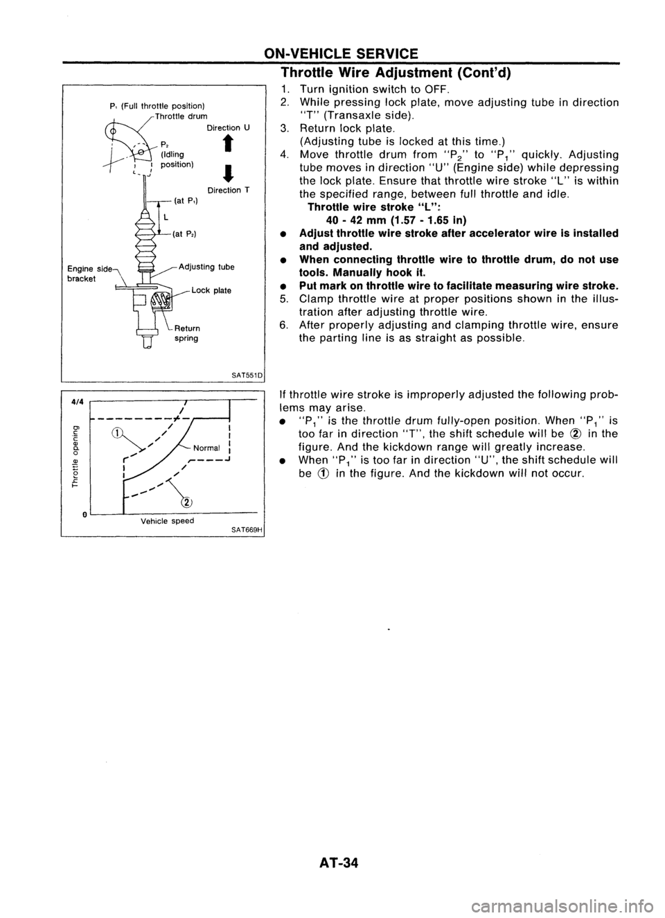
1. Turn ignition switchtoOFF.
2. While pressing lockplate, moveadjusting tubeindirection
"T" (Transaxle side).
3. Return lockplate.
(Adjusting tubeislocked atthis time.)
4. Move throttle drumfrom
"P2"
to
"P
1"
quickly. Adjusting
tube moves indirection "U"(Engine side)while depressing
the lock plate. Ensure thatthrottle wirestroke "L"iswithin
the specified range,between fullthrottle andidle.
Throttle wirestroke "L":
40 -42
mm
(1.57 -1.65
in)
• Adjust throttle wirestroke afteraccelerator wireisinstalled
and adjusted.
• When connecting throttlewiretothrottle drum,donot use
tools. Manually hookit.
• Put mark onthrottle wiretofacilitate measuring wirestroke.
5. Clamp throttle wireatproper positions showninthe illus-
tration afteradjusting throttlewire.
6. After properly adjusting andclamping throttlewire,ensure
the parting lineisas straight aspossible.
SAT551D
4/4
Vehiclespeed
If
throttle wirestroke isimproperly adjustedthefollowing prob-
lems mayarise.
• "P
1"
isthe throttle drumfully-open position.When"P
1"
is
too farindirection
"T",
theshift schedule willbe
@
inthe
figure. Andthekickdown rangewillgreatly increase.
• When
"P1"
istoo farindirection "U",theshift schedule will
be
CD
inthe figure. Andthekickdown willnotoccur.
SAT669H
I
I
Normal :
,- .J
,/
/
,,~/~
/
---------1--
,/
'//
r-/
I
I
o
0>
c:
C
Q)
0-
o
~
2
£
I-
AT-34
Page 80 of 1701
ASSEMBLY
1. Install
a PI upper, inter
. tha~e oilcircuit ofuand lower body
elr pro pperbd .
per posT
0
Yface
I
Ions. up.Install stelb'
e
ails
In
SATOB21
SATOB31
REPAIR
FOR
COMPONE
Control ValNTPARTS
0"1
veAsse b
I
cooler reli
f
mIy(Cont'd)
• Check f
evalve spring
• M ordamag
easure freeIeeor deformation
Inspection
ngthandouter d'.
R
f
standard"
Iameter
of
e er to50S AT.
valvespring
, -167. .
Q
(Length)
Model 34X69and34X70
Model 34X68
Model 34X80
AT-SO
Page 86 of 1701
REPAIRFORCOMPONENT PARTS
Control ValveUpper Body
SEC. 317
OJ
Ql
c:
Cil
.~
c.
(J)
iii
>
u
c:
c: c:
00
Z
~
-J
u
>
Ql
c:~
5
~
>
a:
Ql
@
U
c:
Ql
::J
0-
Ql
(J)
C\I
.;.
iii
0.
0.
::>
OJ
c:
';:
iit
E
::J
~
a:
e
(I)
Cil
c.
iii
c:
'19
Ql
a:
2
co
c.
iii
c:
yg
Ql
a:
Apply ATFtoall components beforetheirinstallation.
Numbers preceding valvesprings correspond withthose shown inSpring ChartofSDS onpage AT-167,
AT-86
SAT2021
Page 87 of 1701
REPAIRFORCOMPONENT PARTS
Control ValveUpper Body(Cont'd)
DISASSEMBL Y
1. Remove valvesatretainer plates.
• Donot use amagnetic "hand".
SAT114D
a.Use ascrewdriver toremove retainer plates.
SAT135D
b.Remove retainerplateswhileholding spring,plugsand•
sleeves.
• Remove plugslowly toprevent internalpartsfromjumping
out.
c. Place mating surface ofvalve facedown, andremove inter-
nal parts.
• If
avalve ishard toremove, placevalvebodyfacedown and
lightly tapitwith asoft hammer.
• Becareful nottodrop ordamage valvesandsleeves.
SAT137D INSPECTION
Q
(Length) Valve
spring
• Measure freelength andouter diameter ofeach valve
spring. Alsocheck fordamage ordeformation.
Inspection standard:
Refer to50S, AT-167.
• Replace valvesprings ifdeformed orfatigued.
Control valves
• Check sliding surfaces ofvalves, sleeves andplugs.
SAT138D
AT-87
Page 90 of 1701
SEC.317
~
o
.0
REPAIR
FORCOMPONENT PARTS
Control ValveLower Body
Ol
::>
i5.
o
o
a.
W
~Ol
::>
a:
~
Cll
m
i5.
Q;
c
'OJ
a;
a:
Apply ATFtoall components beforetheirinstallation.
Numbers preceding valvesprings correspond withthose shown inSpring ChartofSOS onpage AT-167.
AT-gO
SAT532H