Page 429 of 1701
~:N.m (kg-m, ft-Ib)
SEL910T
SEL032Z
SEL033Z CHARGING
SYSTEM
Removal andInstallation
Disassembly
REAR COVER REMOVAL
C~UTION:
Rear cover maybehard toremove because aring isused to
lock outer raceofrear bearing. Tofacilitate removalofrear
cover, heatjustbearing boxsection witha200W soldering iron.
Do not use aheat gun, asitcan damage diodeassembly.
REAR BEARING
CAUTION:
• Do not reuse rearbearing afterremoval. Replacewitha
new one.
• Donot lubricate rearbearing outerrace.
Rotor Check
1. Resistance test
Resistance: RefertoSOS (EL-61).
• Not within thespecified values...Replace rotor.
2. Insulator test
• Continuity exists...Replace rotor.
3. Check slipring forwear.
Slip ring minimum outerdiameter:
Refer toSOS (EL-61).
• Not within thespecified values...Replace rotor.
EL-57
•
Page 447 of 1701

Bulbcover
SEL995K HEADLAMP
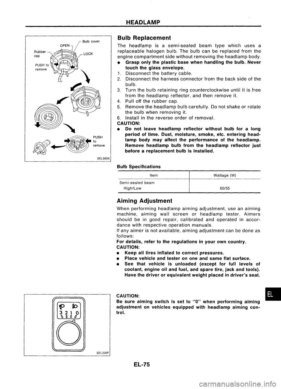
Bulb Replacement
The headlamp isasemi-sealed beamtypewhich usesa
replaceable halogenbulb.Thebulb canbereplaced fromthe
engine compartment sidewithout removing theheadlamp body.
• Grasp onlytheplastic basewhen handling thebulb. Never
touch theglass envelope.
1. Disconnect thebattery cable.
2. Disconnect theharness connector fromtheback sideofthe
bulb.
3. Turn thebulb retaining ringcounterclockwise until
it
is free
from theheadlamp reflector,andthen remove it.
4. Pull offthe rubber cap.
5. Remove theheadlamp bulbcarefully. Donot shake orrotate
the bulb when removing it.
6. Install inthe reverse orderofremoval.
CAUTION:
• Do not leave headlamp reflector withoutbulbforalong
period oftime. Dust,moisture, smoke,etc.entering head-
lamp bodymayaffect theperformance ofthe head lamp.
Remove headlamp bulbfrom thehead lamp reflector just
before areplacement bulbisinstalled.
Bulb Specifications
Item
Semi-sealed beam
High/Low Wattage
(W)
60/55
f>
to
3 21 0
~ nOD
o
SEL226PAiming
Adjustment
When performing headlamp aiming adjustment, useanaiming
machine, aimingwallscreen orheadlamp tester.Aimers
should beingood repair, calibrated andoperated inaccor-
dance withrespective operationmanuals.
If any aimer isnot available, aimingadjustment canbedone as
follows:
For details, refertothe regulations inyour owncountry.
CAUTION:
• Keep alltires inflated tocorrect pressures.
• Place vehicle andtester onone and same flatsurface.
• See thatvehicle isunloaded (exceptforfull levels of
coolant, engineoiland fuel, andspare tire,jack andtools).
Have thedriver orequivalent weightplaced indriver's seat.
CAUTION: •
Be sure aiming switchisset to
"0"
when performing aiming
adjustment onvehicles equipped withheadlamp aiming con-
trol.
EL-75
Page 507 of 1701

METERANDGAUGES
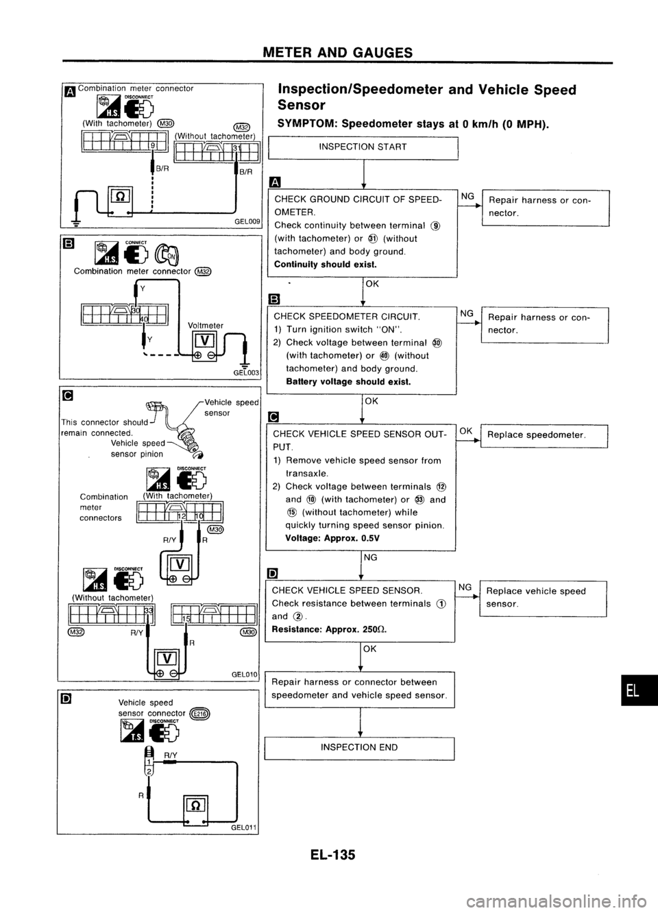
Inspection/Speedometer andVehicle Speed
Sensor
SYMPTOM: Speedometer staysat0km/h (0MPH).
Repair harness orcon-
nector.
Repair harness orcon-
nector.
NG
NG
INSPECTION
START
CHECK GROUND CIRCUITOFSPEED-
OMETER.
Check continuity betweenterminal @
(with tachometer) or@ (without
tachometer) andbody ground.
Continuity shouldexist.
CHECK SPEEDOMETER CIRCUIT.
1) Turn ignition switch"ON".
2) Check voltage between terminal @
(with tachometer) or
@)
(without
GEL003 tachometer) andbody ground.
Battery voltage shouldexist.
Voltmeter GEL009
y
~i)~
Combination meterconnector
@
...
Combination meterconnector
raJ
~i5
(With tachometer)
@ @
rB3mHJB
fifiE
'B/R B/R
I
I
I
I
I
I
I
Repairharness orconnector between
speedometer andvehicle speedsensor.
I;]
CHECK VEHICLE SPEEDSENSOR.
Check resistance betweenterminals
CD
and @.
Resistance: Approx.250ft
•
Replace
speedometer.
Replace vehiclespeed
sensor.
OK
NG
OK
NG
INSPECTION END
CHECK
VEHICLE SPEEDSENSOR OUT-
PUT. 1) Remove vehiclespeedsensor from
transaxle.
2) Check voltage between terminals @
and
@l
(with tachometer) or
@
and
@
(without tachometer) while
quickly turning speedsensor pinion.
Voltage: Approx.0.5V
Vehicle speed
sensor connector ~
~i5
m
RIY
Combination
meter
connectors
~i5
(With tachometer)
rEEElBBE3]
~=IR@
~i5 ~
(Without tachometer)
~ BmEEEa_1
@
RIY~oojR
@
GEL010
[!J
~vehiCle speed
sensor
[!J
This connector should
remain connected..
Vehicle speed .
sensor pinion ~
R
GEL011EL-135
Page 508 of 1701
INSPECTIONSTART
Is vehicle speedsensor installed prop-NG
Install vehicle speedsen-
erly? Check looseness andsoon.
----..
sorproperly.
OK
m
Do you feel resistance whenturning No
Replace vehiclespeed
----..
vehicle speedsensor pinion? sensor.
Yes
Ii)
Check continuity betweenspeedometer NG
Repair harness andcon-
terminals andvehicle speedsensor
---..
nector.
terminals. Continuity shouldexist.
Vehicle
Combination meterterminal speed
sensor
terminal
@
With tachometer
@
@
Without tachometer
@
OK
Replace speedometer.
METER
ANDGAUGES
Inspection/Speedometer andVehicle Speed
Sensor (Cont'd)
SYMPTOM: Speedometer indicationflutters.
GEL012
Vehicle
speedsensor
connector
@ID
~ DISCONNECT
rID
~y
Ie::
~ &5 ~
_-----J
(Without tachometer) I
~l ICombination
~'IJU
Imeter
"-=
R'connectors
@
~ RIY
I
BElmmI
___________ '
Combination
meterconnector AEL061
~io
(With tachometer)
~
@
RIY R
Speed
sensor pinion
EL-136
Page 509 of 1701
METERANDGAUGES
Fuel Tank Gauge UnitCheck
• For removal, refertoFE section ("FUEL SYSTEM").
Check theresistance betweenterminals (G)and (E).
*1 and '3:When floatrodisin contact withstopper.
Thermal Transmitter Check
Check theresistance betweentheterminals ofthermal trans-
mitter andbody ground.
Ohmmeter
Resistance
Float position mm(in) value
(+)
H
(0)
'3 Full 36
(1.42) Approx.4-6
G E
'2 1/2
86(3.39) 27-35
'1 Empty
131(5.16) 78-85
Approx. 70-90Q
Approx. 21-24Q
Resistance
60'G (140'F)
100'G (212'F)
Water
temperature
'1
MEL622D
Ohmmeter
~- SEL233P
~ Vehiclespeed
~ ~sensor
~y<
Voltmeter {/l
[Y]
Approx. O.5V
[Alternating
current (AG)] Vehicle
SpeedSensor SignalCheck
1. Remove vehiclespeedsensor fromtransaxle.
2. Turn speedometer pinionquickly andmeasure voltage
across
CD
and ~.
SEL840T
•
EL-137
Page 553 of 1701

POWERWINDOW
System Description (Cont'd)
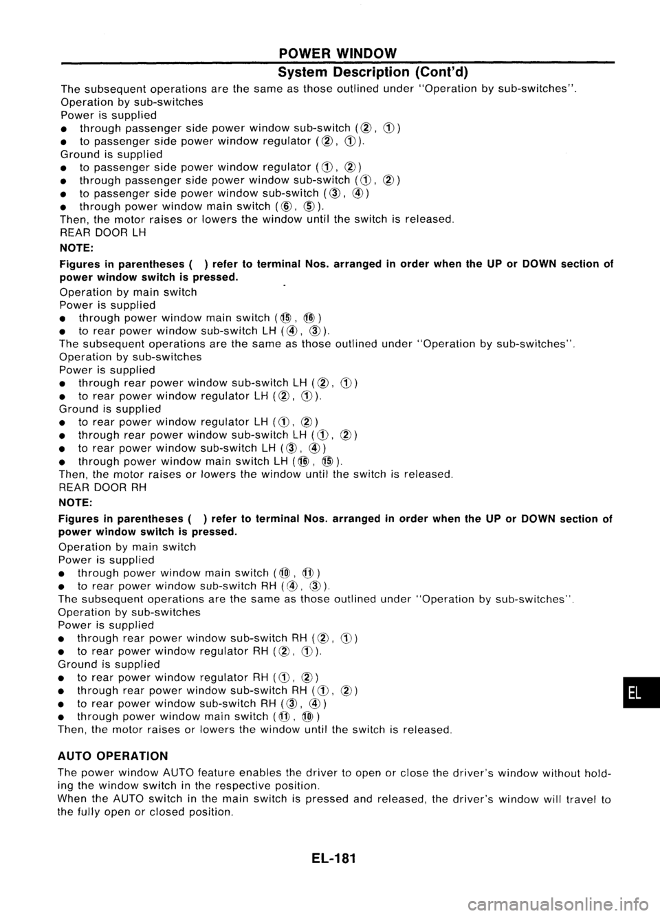
The subsequent operationsarethesame asthose outlined under"Operation bysub-switches".
Operation bysub-switches
Power issupplied
• through passenger sidepower window sub-switch (@,
CD)
• topassenger sidepower window regulator
(@,
CD).
Ground issupplied
• topassenger sidepower window regulator
(CD,
@)
• through passenger sidepower window sub-switch
(CD,
@)
• topassenger sidepower window sub-switch
(CID,
@)
• through powerwindow mainswitch (@,
@)).
Then, themotor raises orlowers thewindow untiltheswitch isreleased.
REAR DOOR LH
NOTE:
Figures inparentheses ()refer toterminal Nos.arranged inorder whentheUPorDOWN section of
power window switchispressed.
Operation bymain switch
Power issupplied
• through powerwindow mainswitch (@,@)
• torear power window sub-switch LH(@,
CID).
The subsequent operationsarethesame asthose outlined under"Operation bysub-switches".
Operation bysub-switches
Power issupplied
• through rearpower window sub-switch LH(@,
CD)
• torear power window regulator LH(@,
CD).
Ground issupplied
• torear power window regulator LH
(CD,
@)
• through rearpower window sub-switch LH
(CD,
@)
• torear power window sub-switch LH
(CID,
@)
• through powerwindow mainswitch LH(@, @).
Then, themotor raises orlowers thewindow untiltheswitch isreleased.
REAR DOOR RH
NOTE:
Figures inparentheses ()refer toterminal Nos.arranged inorder whentheUPorDOWN section of
power window switchispressed.
Operation bymain switch
Power issupplied
• through powerwindow mainswitch
(@J,
@)
• torear power window sub-switch RH(@,
CID).
The subsequent operationsarethesame asthose outlined under"Operation bysub-switches".
Operation bysub-switches
Power issupplied
• through rearpower window sub-switch RH(@,
CD)
• torear power window regulator RH(@,
CD).
Ground issupplied
• torear power window regulator RH
(CD,
@) •
• through rearpower window sub-switch RH
(CD,
@)
• torear power window sub-switch RH
(CID,
@)
• through powerwindow mainswitch (@,@)
Then, themotor raises orlowers thewindow untiltheswitch isreleased.
AUTO OPERATION
The power window AUTOfeature enables thedriver toopen orclose thedriver's windowwithouthold-
ing the window switchinthe respective position.
When theAUTO switch inthe main switch ispressed andreleased, thedriver's windowwilltravel to
the fully open orclosed position.
EL-181
Page 723 of 1701
PRECAUTIONSANDPREPARATION
Special Service Tools
Tool number
Tool name Description Engine
application
SR GA
EG11140000
Ignition coiladapter
harness
KV10117100
Heated oxygen sensor
wrench
KV10114400
Oxygen sensorwrench
NT338
NT630
NT636
Measuring
enginespeed
Loosening ortightening
heated oxygen sensor
Loosening orlightening
heated oxygen sensor
a: 22 mm (0.87 in)
x
x
x
x
FOR CDENGINE VE-TYPE INJECTION PUMP
Adjusting deviceonvehicle
Tool number
Tool name Description
KV11229352
Measuring device
CD
KV11229350
Holder
@ KV11229360
Nut
@ KV11229370
Pin
@ KV11254410
Dial gauge
KV11102900
Pulley puller
NT570
NT647
EC-4
Measuring
setlength ofplunger spring
Removing injectionpumpsprocket
Page 728 of 1701

PRECAUTIONSANDPREPARATION
I
GA, SR
I
Precautions forECCS Trouble Diagnosis of
Engine
CAUTION:
• Besure toturn theignition switch"OFF" anddisconnect thenegative batteryterminal beforeany
repair orinspection work.Theopen/short circuitofrelated switches, sensors,solenoidvalves,etc.
will cause malfunction.
• Besure toconnect andlock theconnectors securelyafterwork. Aloose (unlocked) connectorwill
cause malfunction duetothe open circuit. (Besure theconnector isfree from water, grease, dirt,
bent terminals, etc.)
• Besure toroute andclamp theharnesses properlyafterwork. Theinterference ofthe harness with
a bracket, etc.may cause malfunction duetothe short circuit.
• Besure toconnect rubbertubesproperly afterwork. Amisconnected ordisconnected rubbertube•
may cause malfunction.
• Besure toerase theunnecessary malfunctioninformation(repairscompleted) inthe ECM before
returning thevehicle tothe customer.
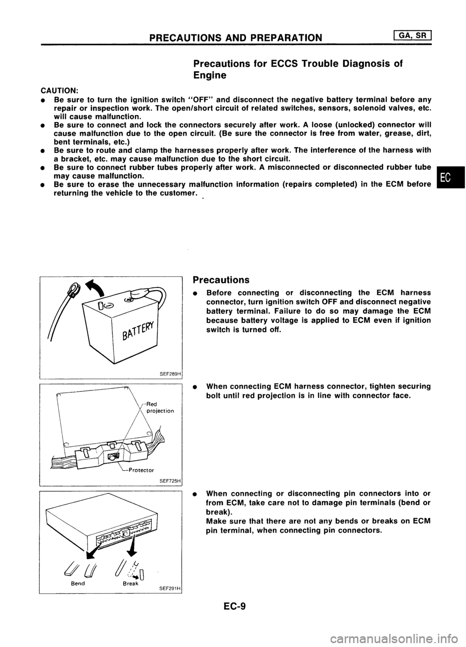
Precautions
• Before connecting ordisconnecting theECM harness
connector, turnignition switchOFFanddisconnect negative
battery terminal. Failuretodo somay damage theECM
because batteryvoltage isapplied toECM even ifignition
switch isturned off.
SEF289H
•When connecting ECMharness connector, tightensecuring
bolt until redprojection isin line with connector face.
SEF725H
•When connecting ordisconnecting pinconnectors intoor
from ECM, takecare nottodamage pinterminals (bendor
break). Make surethatthere arenotany bends orbreaks onECM
pin terminal, whenconnecting pinconnectors.
Bend Break
SEF291H
EC-9