1995 NISSAN ALMERA N15 ESP
[x] Cancel search: ESPPage 781 of 1701
TROUBLEDIAGNOSIS -General Description
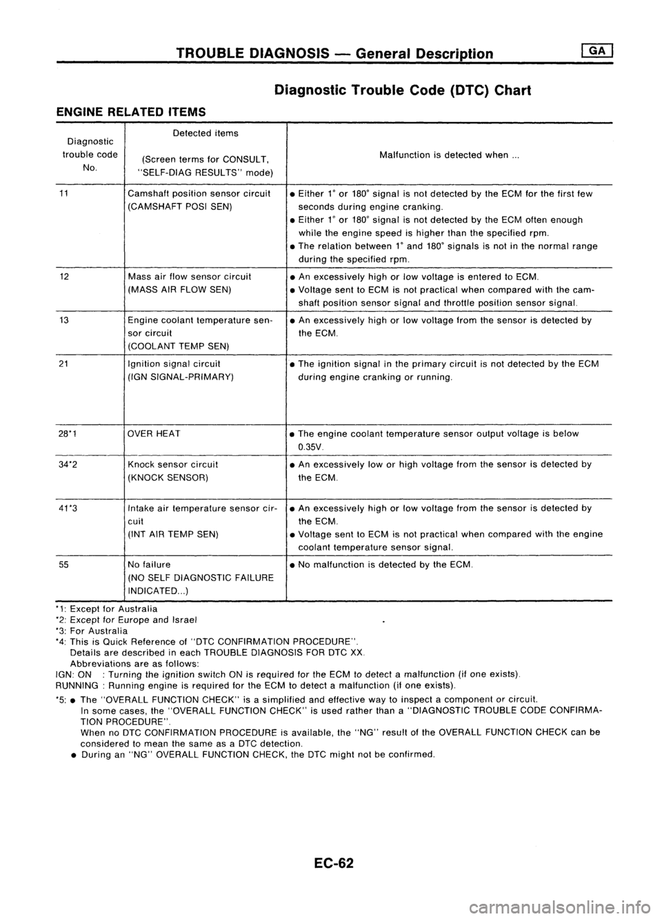
Diagnostic TroubleCode(DTC) Chart
ENGINE RELATED ITEMS
Detected items
Diagnostic
trouble code
(ScreentermsforCONSULT, Malfunction
isdetected when...
No. "SELF-DIAG RESULTS"mode)
11 Camshaftpositionsensorcircuit
•Either
l'
or 180' signal isnot detected bythe ECM forthe first few
(CAMSHAFT POSISEN)
secondsduringengine cranking .
• Either
l'
or 180' signal isnot detected bythe ECM often enough
while theengine speedishigher thanthespecified rpm.
• The relation between
l'
and 180' signals isnot inthe normal range
during thespecified rpm.
12 Massairflow sensor circuit
•An excessively highorlow voltage isentered toECM.
(MASS AIRFLOW SEN) •Voltage senttoECM isnot practical whencompared withthecam-
shaft position sensorsignalandthrottle position sensorsignal.
13 Enginecoolant temperature sen-•An excessively highorlow voltage fromthesensor isdetected by
sor circuit
theECM.
(COOLANT TEMPSEN)
21 Ignitionsignalcircuit
•The ignition signalinthe primary circuitisnot detected bythe ECM
(IGN SIGNAL-PRIMARY)
duringengine cranking orrunning .
28*1 OVERHEAT •The engine coolant temperature sensoroutputvoltage isbelow
0.35V .
34"2 Knocksensor circuit •An excessively loworhigh voltage fromthesensor isdetected by
(KNOCK SENSOR) theECM.
41 *3 Intakeairtemperature sensorcir-•An excessively highorlow voltage fromthesensor isdetected by
cuit theECM.
(INT AIRTEMP SEN) •Voltage senttoECM isnot practical whencompared withtheengine
coolant temperature sensorsignal.
55
Nofailure •No malfunction isdetected bythe ECM.
(NO SELF DIAGNOSTIC FAILURE
INDICATED ...)
"1: Except forAustralia
*2: Except forEurope andIsrael
"3: For Australia
*4: This isQuick Reference of"DTC CONFIRMATION PROCEDURE".
Details aredescribed ineach TROUBLE DIAGNOSIS FORDTCXX
Abbreviations areasfollows:
IGN: ON :Turning theignition switchONisrequired forthe ECM todetect amalfunction (ifone exists).
RUNNING: Runningengineisrequired forthe ECM todetect amalfunction (ifone exists).
*5: •The "OVERALL FUNCTIONCHECK"isasimplified andeffective waytoinspect acomponent orcircuit.
In some cases, the"OVERALL FUNCTIONCHECK"isused rather thana"DIAGNOSTIC TROUBLECODECONFIRMA-
TION PROCEDURE".
When noDTC CONFIRMATION PROCEDUREisavailable, the"NG" result ofthe OVERALL FUNCTION CHECKcanbe
considered tomean thesame asaDTC detection .
• During an"NG" OVERALL FUNCTION CHECK,theDTC might notbeconfirmed.
EC-62
Page 783 of 1701
TROUBLEDIAGNOSIS -General Description
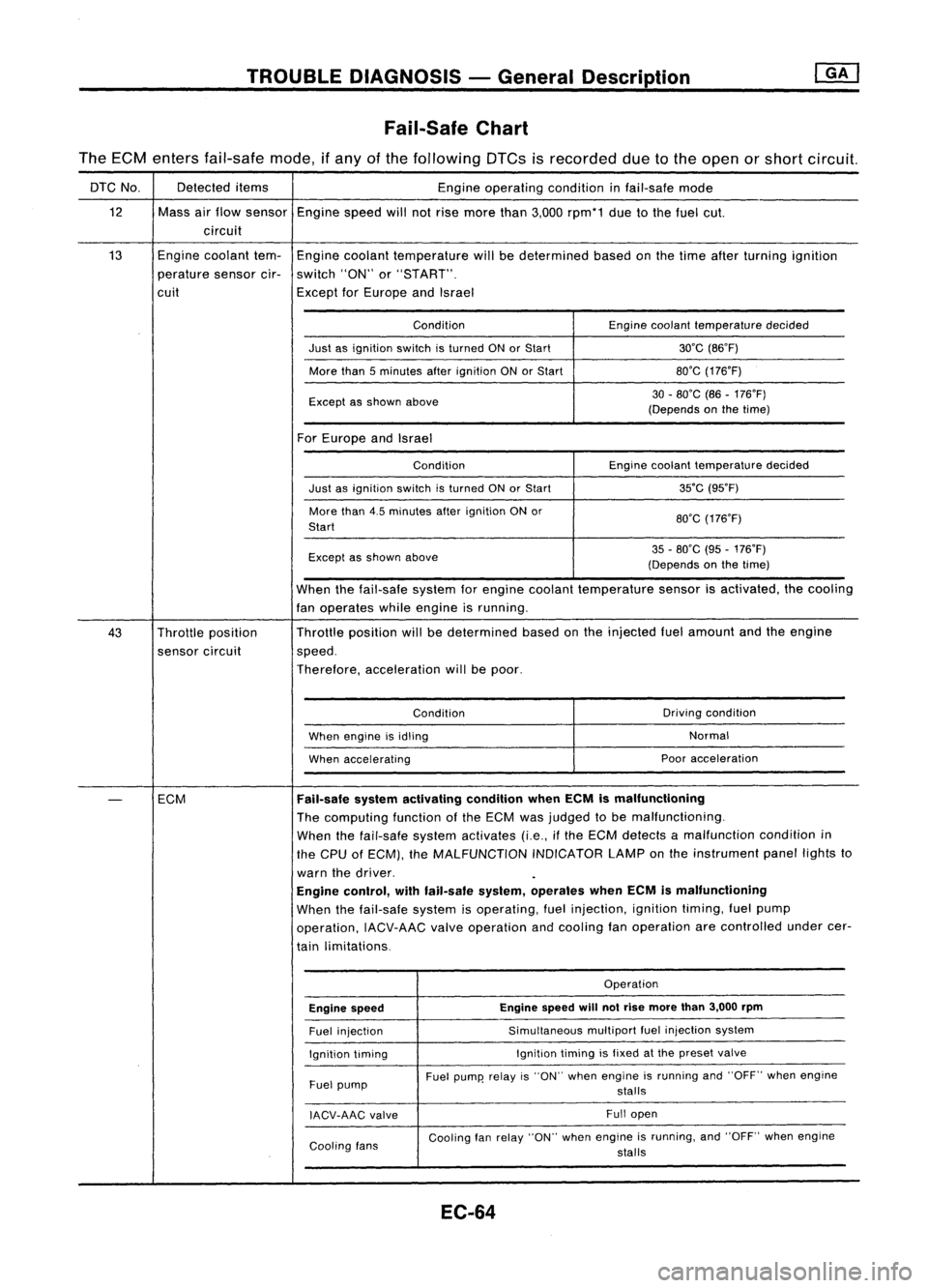
Fail-Safe Chart
The ECM enters fail-safe mode,ifany ofthe following DTCsisrecorded duetothe open orshort circuit.
DTC No. Detected
items
Engineoperating conditioninfail-safe mode
12 Massairflow sensor
Enginespeedwillnotrise more than3,000 rpm*1 duetothe fuel cut.
circuit
13 Engine
coolant tem-
Engine coolant temperature willbedetermined basedonthe time after turning ignition
perature sensorcir-switch "ON"or"START".
cuit ExceptforEurope andIsrael
Condition Enginecoolant temperature decided
Just asignition switchisturned ONorStart 30'C(B6'F)
More than5minutes afterignition ONorStart BO'G
(176'F)
Except asshown above 30
-BO'C (B6-176'F)
(Depends onthe time)
For Europe andIsrael
Condition Enginecoolant temperature decided
Just asignition switchisturned ONorStart 35'C
(95'F)
More than4.5minutes afterignition ONor
BO'G(176'F)
Start
Except asshown above 35
-BO'C (95-176'F)
(Depends onthe time)
When thefail-safe systemforengine coolant temperature sensorisactivated, thecooling
fan operates whileengine isrunning.
43 Throttle position Throttle
position willbedetermined basedonthe injected fuelamount andtheengine
sensor circuit speed.
Therefore, acceleration willbepoor.
Condition Driving
condition
When engine isidling Normal
When accelerating Poor
acceleration
-
ECM
Fail-safe
systemactivating conditionwhenECMismalfunctioning
The computing functionofthe ECM wasjudged tobe malfunctioning.
When thefail-safe systemactivates (i.e.,ifthe ECM detects amalfunction conditionin
the CPU ofECM), theMALFUNCTION INDICATORLAMPonthe instrument panellightsto
warn thedriver.
Engine control, withfail-safe system,operates whenECMismalfunctioning
When thefail-safe systemisoperating, fuelinjection, ignitiontiming,fuelpump
operation, IACV-AACvalveoperation andcooling fanoperation arecontrolled undercer-
tain limitations.
Operation
Engine speed Engine
speed
will
notrise more than3,000 rpm
Fuel injection Simultaneous
multipartfuelinjection system
Ignition timing Ignition
timingisfixed atthe preset valve
Fuel pump Fuel
pump' relayis"ON" when engine isrunning and"OFF" whenengine
stalls
IACV-AAG valve Full
open
Cooling fans Cooling
fanrelay "ON" whenengine isrunning, and"OFF" whenengine
stalls
EC-64
Page 785 of 1701
![NISSAN ALMERA N15 1995 Service Manual @
(Go tonext page)
(;]
1
CHECK IDLEADJ. SCREW INITIALSET
NG
Adjust engine speedby
~
RPM.
turning
idleadjusting
Base idlespeed: RefertoEC-36.
screw.
II
t
K
CHECK THROTTLE POSITIONSENSOR
NG
NISSAN ALMERA N15 1995 Service Manual @
(Go tonext page)
(;]
1
CHECK IDLEADJ. SCREW INITIALSET
NG
Adjust engine speedby
~
RPM.
turning
idleadjusting
Base idlespeed: RefertoEC-36.
screw.
II
t
K
CHECK THROTTLE POSITIONSENSOR
NG](/manual-img/5/57349/w960_57349-784.png)
@
(Go tonext page)
(;]
1
CHECK IDLEADJ. SCREW INITIALSET
NG
Adjust engine speedby
~
RPM.
turning
idleadjusting
Base idlespeed: RefertoEC-36.
screw.
II
t
K
CHECK THROTTLE POSITIONSENSOR
NG
Adjust output
voltage
to
~
IDLE POSITION.
0.50
:l:
0.1V byrotating
00
1.
Perform ''THRTlPOSSEN throttle
position sensor
ADJ" in"WORK SUPPORT" body.
mode.
2. Check thatoutput
voltage
of
throttle position sensoris
approx. 0.35to0.65V (Throttle
valve
fullycloses.) and"ClSD
THlIP SW"stays "ON".
OR
00
Measure
output
voltage
ofthrot-
tle position sensorusing
voltmeter,
andcheck thatitis
approx. 0.35to0.65V. (Throttle
valve
fullyclosed.)
OK
RESETIDLEPOSITION
MEMORY.
1. Warm upengine suffi-
ciently.
2. Turn ignition switch
"OFF" andwait at
least 5seconds.
3. Disconnect
throttle
position sensorhar-
ness connector.
4.
Start
engine andwait
at least 5seconds in
"N" position .
5. Reconnect throttle
position sensorhar-
ness connector while
running engine.
TROUBLE
DIAGNOSIS -General Description
Basic Inspection (Coni'd)
@
• THRTl POSSEN ADJ.
0
* **
ADJ MONITOR
***
THRTL POSSEN 0.52V
==========
MONITOR
==========
CMPS.RPM (REF)Orpm
CLSD THLIPOSI ON
SEF516Q
SEF12BR EC-66
Page 786 of 1701
TROUBLEDIAGNOSIS -General Description
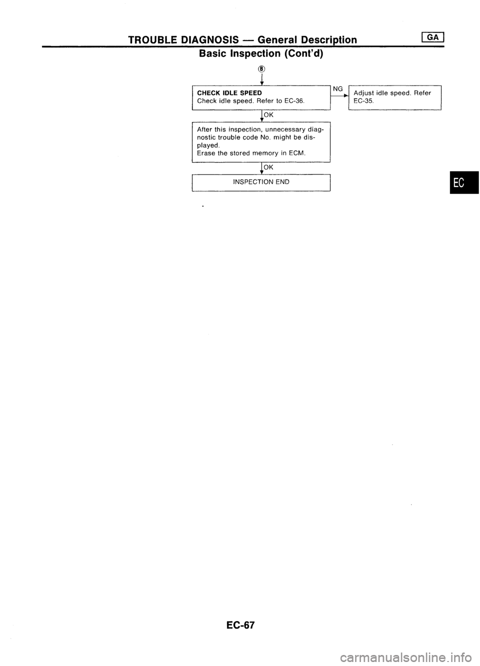
Basic Inspection (Cont'd)
CID
CHECK IDLESPEED
Check idlespeed. RefertoEC-36.
OK
After thisinspection, unnecessary diag-
nostic trouble codeNo.might bedis-
played.
Erase thestored memory inECM.
OK
INSPECTION END
EC-67 NG
Adjust idlespeed. Refer
EC-35.
•
Page 790 of 1701
TROUBLEDIAGNOSES -General Description
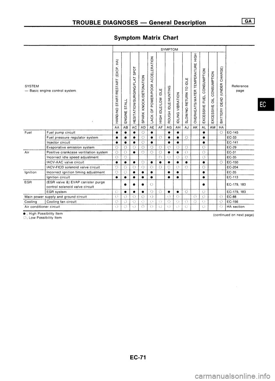
Symptom MatrixChart
SYMPTOM
:c
z
(!l
~
0
I
:c
i=
w
cL
~
<{
0::
0::
='
W
<.)
0
w
~
z
CJ
x
Cl.
-I
0
Z
0::
~
en
w
i=
0
z
<.)
0::
<{
~
0
<.)
w
w
Cl.
i=
:c
~
-I
Cl.
::?
Cl.
<.)
0::
-I
i=
<{
Q
::?
=' ::?
<{
u..
<{
0::
SYSTEM
0::
W
en
='
Reterence
~
0
CJ
0
~
z
w
en
0
w
z
0
en
0
- Basic engine control system
w
z
0
~
0::
Z
Z
page
0::
<3
~
Cl.
-I
i=
w
<.)
0
w
Q
z
z
2-
j:::
0::
0
ii
z
0
0::
~
-I
<.)
0::
='
;;:
w
:s:
='
i=
='
<{
W
-I
0
<{
-I
en
:s:
:c
~
:s:
='
6
<{
-I
Z
<.)
0
w
<{
w
en
u..
w
~
<{
00
-I
0::
en
~
Cl.
W
-I
III
0::
~
W
W
0
0
en
0
z
Q
:;
0
<{
> >
i=
~
LL
-I
>-
Z
W
0
Q
z
w
U5 U5
0::
2i
z
<{
~ :c
(!l
~:c
en en
w
<3
~
0::
~
:c
CJ
z
0::
W W
~
0::
U5
<{
<.)
CJ
='
:J
0
w
<.)
<.)
~
I
<{
Z
W
Cl.
<{
0
Q
-I
>
X
X
<{
:c
w
:c
en
-I
:c
0::
en
0
w
W
III
AA AB AC ADAEAFAG
AH AJ
AK AL
AM HA
Fuel Fuel
pump circuit
••
•
0
•
•
•
•
0
EC-145
Fuel pressure regulator system
•••
0
•
0
•
•
0
•
EC-33
Injector circuit
•• •
0
• •
• •
EC-141
Evaporative emissionsystem
00
[)
00
()
0
0 0 0
EC-29
Air Positivecrankcase ventilation system
00
•
0
0
0
••
U
()
EC-31
Incorrect idlespeed adjustment
0
0
()
(~)
C)
0 0
EC-35
IACV-AAC valvecircuit
•••
(,
••• •• •
0
EC-150
~)
IACV-FICD solenoidvalvecircuit
C)
()
()
()
0
C)
(~,
()
0
0
EC-204
Ignition Incorrectignitiontimingadjustment
0
0
•• •
•
• •
EC-35
Ignition circuit
••
•
•
• •
•
•
EC-113
EGR (EGRvalve
&)
EVAP canister purge
0
EC-179,183
control soienoid valvecircuit
••
• •
EGR system
U
••
•
r)
(,)
•
•
0
0
EC-179.
183
Main power supply andground circuit
()
() ()
0 0
()
Ci
()
0
(
~
EC-88
Cooling
I
Cooling tancircuit
()
:.'-1
U
()
(,)
',)
C)
t)
U
n
(J
0
EC-156
u
Air conditioner circuit
()
Co
u
()
CJ
UU
"
,
C:
~,
()
HAsection
•
• ;High Possibility Item
(), Low Possibility Item
EC-71
(continued
onnext page)
Page 793 of 1701
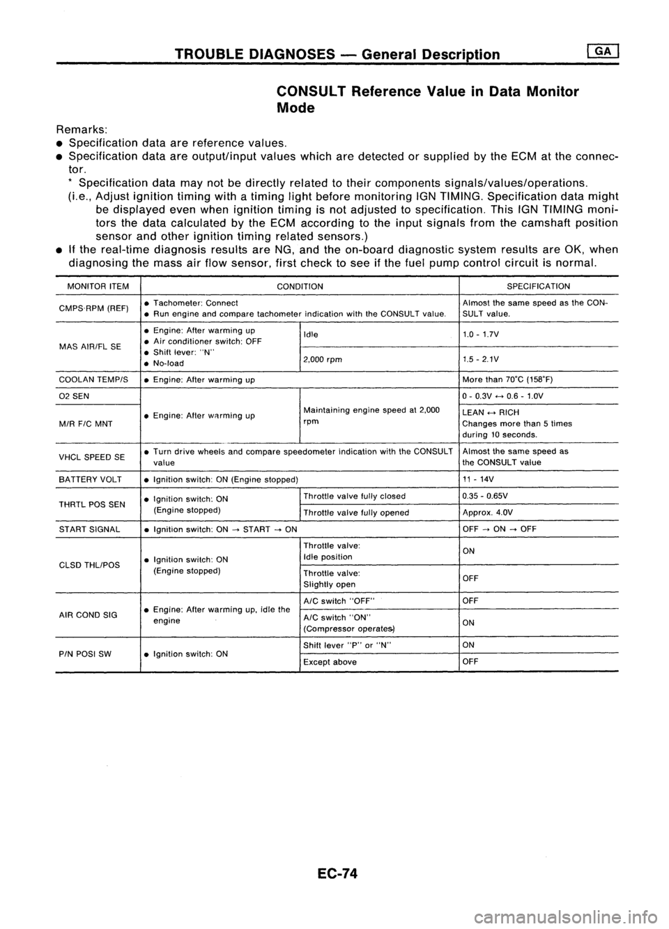
TROUBLEDIAGNOSES -General Description
CONSULT ReferenceValueinData Monitor
Mode
Remarks:
• Specification dataarereference values.
• Specification dataareoutput/input valueswhicharedetected orsupplied bythe ECM atthe connec-
tor.
*
Specification datamaynotbedirectly relatedtotheir components signals/values/operations.
(Le., Adjust ignition timingwithatiming lightbefore monitoring IGNTIMING. Specification datamight
be displayed evenwhen ignition timingisnot adjusted tospecification. ThisIGNTIMING moni-
tors thedata calculated bythe ECM according tothe input signals fromthecamshaft position
sensor andother ignition timingrelated sensors.)
• Ifthe real-time diagnosis resultsareNG, and theon-board diagnostic systemresultsareOK, when
diagnosing themass airflow sensor, firstcheck tosee ifthe fuel pump control circuitisnormal.
MONITOR ITEM
CONDITION SPEC
IFICA TION
CMPS.RPM (REF)•
Tachometer: Connect Almostthesame speed asthe CON-
• Run engine andcompare tachometer indicationwiththeCONSULT value.SULT value.
• Engine: Afterwarming up
Idle 1.0
-1.7V
MAS AIRIFL SE •
Air conditioner switch:OFF
• Shift lever: "N"
• No-load 2,000
rpm 1.5
-2.1V
COOLAN TEMPIS •Engine: Afterwarming up More
than70°C (158°F)
02 SEN 0-
0.3V
<-+
0.6 -1.0V
• Engine: Afterwflrming up Maintaining
enginespeedat2,000
LEAN
<-+
RICH
MIR
FIC
MNT rpm
Changesmorethan5times
during 10seconds .
VHCL SPEED SE•
Turn drive wheels andcompare speedometer indicationwiththeCONSULT Almost
thesame speed as
value the
CONSULT value
SA TTERY VOLT •Ignition switch:ON(Engine stopped) 11
-14V
• Ignition switch:ON Throttle
valvefullyclosed 0.35
-0.65V
THRTL POSSEN
(Enginestopped)
Throttlevalvefullyopened Approx.
4.0V
ST ART SIGNAL •Ignition switch:ON
-->
START
-->
ON OFF
-->
ON
-->
OFF
Throttle valve:
ON
• Ignition switch:ON Idle
position
CLSD THLIPOS
(Enginestopped)
Throttlevalve:
OFF
Slightly open
AIC
switch "OFF" OFF
AIR COND SIG •
Engine: Afterwarming up,idle the
engine
AIC
switch "ON"
ON
(Compressor operate&)
Shift lever "P"or"N" ON
PIN POSI SW •Ignition switch:ON
Exceptabove OFF
EC-74
Page 794 of 1701
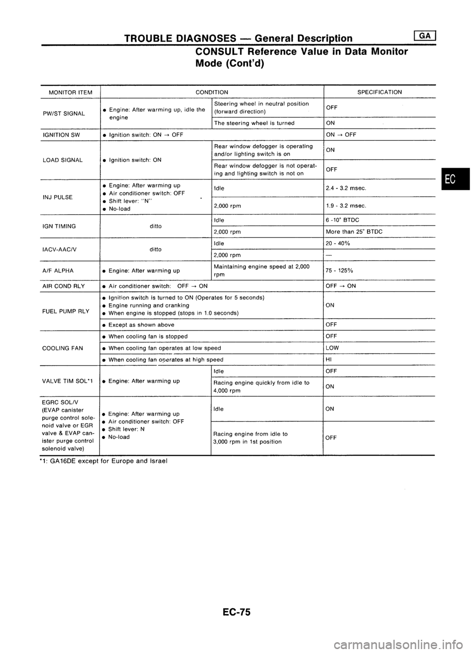
TROUBLEDIAGNOSES -General Description @KJ
CONSULT Reference ValueinData Monitor
Mode (Cont'd)
MONITOR ITEM CONDITION
SPECIFICATION
Steering wheelinneutral position
OFF
PW/ST SIGNAL •
Engine: Afterwarming up.idle the
(forward direction)
engine Thesteering wheelisturned ON
IGNITION SW •
Ignition switch:ON
-->
OFF ON
-->
OFF
Rear window defogger isoperating
ON
and/or lighting switchison
LOAD SIGNAL •
Ignition switch:ON
Rearwindow defogger isnot operat-
OFF
ing and lighting switchisnot on
• Engine: Afterwarming up
Idle 2.4
-3.2 msec.
INJ PULSE •
Air conditioner switch:OFF
• Shift lever: "N"
.
• No-load 2.000
rpm 1.9
-3.2 msec.
Idle 6
_10' BTDC
IGN TIMING ditto
2.000rpm More
than25'BTDC
Idle 20-40%
IACV-AACIV ditto
2.000rpm
-
A/F ALPHA •
Engine: Afterwarming up Maintaining
enginespeedat2.000
75-125%
rpm
AIR COND RLY •
Air conditioner switch:OFF
-->
ON OFF
-->
ON
• Ignition switchisturned toON (Operates for5seconds)
• Engine running andcranking ON
FUEL PUMP RLY
•When engine isstopped (stopsin1.0 seconds)
• Except asshown above OFF
• When cooling fanisstopped OFF
COOLING FAN •
When cooling fanoperates atlow speed LOW
• When cooling fano!Jerates athigh speed HI
Idle OFF
VALVE TIMSOL'1 •Engine: Afterwarming up
Racingenginequickly fromidleto
4.000 rpm ON
EGRC SOLIV
(EVAP canister Idle
ON
purge control sole-•
Engine: Afterwarming up
• Air conditioner switch:OFF
noid valve orEGR
•Shift lever: N
valve
&
EVAP can-
•No-load Racing
enginefromidleto
ister purge control
3.000rpmin1st position OFF
solenoid valve)
*1: GA16DE exceptforEurope andIsrael
EC-75
•
Page 799 of 1701
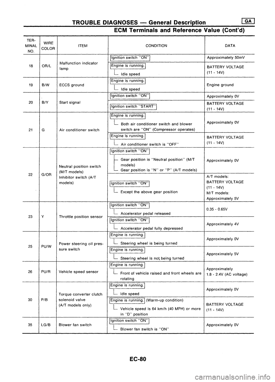
TROUBLEDIAGNOSES -General Description ~
ECM Terminals andReference Value(Cont'd)
TER- WIRE
MINAl ITEM CONDITION DATA
NO. COLOR
/'gnitionswitch"ON'" Approximately
50mV
18 OR/l Malfunction
indicator
I
Engine isrunning.
I
lamp BATTERY
VOLTAGE
L
Idle speed (11.14V)
19 BIW ECCS
ground
I
Engine isrunning.
I
Engineground
L
Idle speed
I'gnition switch"ON"
I
ApproximatelyOV
20 BIY
Startsignal
BATTERYVOLTAGE
I'gnition switch"5TART"
I
(11-14V)
I
Engine isrunning.
I
L
Both airconditioner switchandblower Approximately
OV
21 G Airconditioner switch switch
are"ON" (Compressor operates)
IEngine isrunning.
I
BATTERYVOLTAGE
L
Airconditioner switchis"OFF" (11
-14V)
I'gnition switch"ON'"
t
Ge.,
po,"'on "
"Ne"".1
po,ltlon"
(MIT
Approximately OV
Neutral position switch models)
(M/T
models) Gear
position is"N" or"P"
(A/T
models)
22
G/OR
Inhibitorswitch
(A/T AIT
models:
models) llgnitionswitch"ON'" BATTERY
VOLTAGE
L
Except theabove gearposition (11
-14V)
M/T
models:
Approximately 5V
Ilgnition switch"ON"
I
0.35-0.65V
L
Accelerator pedalreleased
23 Y Throttleposition sensor
!'gnitionswitch"ON"
I
L
Accelerator pedalfullydepressed Approximately
4V
/Engine isrunning.1
ApproximatelyOV
25 Pu/W Power
steering oilpres-
L
Steering wheelisbeing turned
sure switch
IEngineisrunning.1
L
Steering wheelisnot being turned Approximately
5V
I
Engine isrunning.
I
Approximately
26 PUIR Vehiclespeedsensor
L
Front ofvehicle raisedandfront wheels are
1.8-2.4V (ACvoltage)
rotating
I
Engine isrunning.
I
ApproximatelyOV
Torque converter clutch
L
Idle speed
30 PIB
solenoidvalve
I
Engine isrunning.
I
(Warm-up condition)
(A/T
models only)
L
Vehicle speedis64 km/h (40MPH) ormore BATTERY
VOLTAGE
(11-14V)
in "D" position
35 lG/B Blower
fanswitch I,gnition
switch"ON",
ApproximatelyOV
L
Blower fanswitch is"ON"
EC-80