Page 801 of 1701
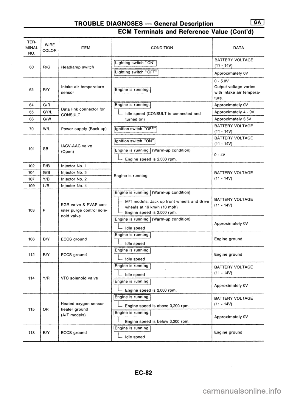
TROUBLEDIAGNOSES -General Description ~
ECM Terminals andReference Value(Conl'd)
TER- WIRE
MINAL COLOR ITEM
CONDITION DATA
NO.
ILightingswitch"ON"I BATTERY
VOLTAGE
60
RIG
Headlamp switch (11
-14V)
ILighting switch"OFF"I
ApproximatelyOV
0- 5.0V
63 RIY Intake
airtemperature
I
Engine isrunning.
I
Output
voltage varies
sensor with
intake airtempera-
ture.
64 GIR
I
Engine isrunning.
I
Approximately
OV
65 GY/L Data
linkconnector for
L
Idle speed (CONSULT isconnected andApproximately
4-9V
CONSULT
68
GIW
turnedon) Approximately
3.5V
I,gnition switch"OFF"
I
BATTERY
VOLTAGE
70
W/L
Powersupply (Back-up)
(11-14V)
Ilgnition switch"ON"I BA
TTERY VOLTAGE
IACV-AAC valve (11
-14V)
101 SS
(Open)
I
Engine isrunning.
I
(Warm-up condition)
L
Engine speedis2,000 rpm. 0-
4V
102 RIB Injector
No.1
104
GIS
InjectorNo.3
BATTERYVOLTAGE
107 YIB InjectorNo.2 Engine
isrunning
(11-14V)
109 LIB Injector
No.4
IEngineisrunning.
I
(Warm-up condition)
~ MIT
models: Jackupfront wheels anddrive BATTERY
VOLTAGE
EGR valve
&
EVAP can-
L
wheels at16 kmlh (10mph) (11
-14V)
103 P
.isterpurge control sole-
Enginespeedis2,000 rpm.
noid valve
IEngineisrunning.
I
(Warm-up condition)
L
Idle speed Approximately
OV
106 BIY ECCSground
I
Engine isrunning.
I
Engineground
L
Idle speed
112 BIY ECCS
ground
I
Engine isrunning.
I
Engineground
L
Idle speed
I Engine isrunning.
I
BATTERYVOLTAGE
L
Idle speed
.
(11-14V)
114 YIR VTCsolenoid valve
I
Engine isrunning.
I
L
Engine speedis2,000 rpm. Approximately
OV
IEngine isrunning.
I
BATTERYVOLTAGE
Heated oxygen sensor
L
Engine speedisabove 3,200rpm. (11
-14V)
115 OR heaterground
IEngine isrunning.
I
(A/T models)
ApproximatelyOV
L
Engine speedisbelow 3,200rpm.
118 SlY ECCS
ground
I
Engine isrunning.
I
Engineground
L
Idle speed
EC-82
Page 803 of 1701
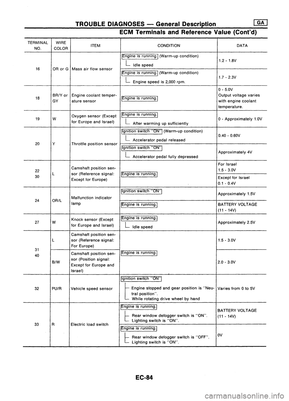
TROUBLEDIAGNOSES -General Description
rnJ
ECM Terminals andReference Value(Cont'd)
TERMINAL WIRE
CONDITION
NO. COLOR ITEM
DATA
IEngine isrunning./ (Warm-up condition)
1.2-1.8V
L
Idle speed
16 ORorG Mass airflow sensor
IEngineisrunning.1 (Warm-up condition)
1.7-2.3V
L
Engine speedis2,000 rpm.
0-5.0V
18 BR/Yor
Enginecoolant temper-
IEngineisrunning.' Output
voltage varies
GY aturesensor with
engine coolant
temperature.
19 W Oxygen
sensor(Except IEngine
isrunning.1
o-
Approximately 1.0V
for Europe andIsrael)
L
After warming upsufficiently
Ilgnition switch"ON"I(Warm-up condition)
0.40-0.60V
L
Accelerator pedalreleased
20 Y Throttlepositionsensor
jlgnitionswitch"ON"I
L
Accelerator pedalfullydepressed Approximately
4V
For Israel
22 Camshaft
positionsen-
1.5-3.0V
30 L
sor(Reference signal:
IEngineisrunning.1
Except forEurope) Except
forIsrael
0.1 -0.4V
Ilgnition switch"ON'"
Approximately1.5V
24 ORIL Malfunction
indicator
lamp IEngineisrunning.1 BATIERY
VOLTAGE
(11 -14V)
27 W Knock
sensor (Except IEngine
isrunning.1
Approximately2.5V
for Europe andIsrael)
L
Idle speed
Camshaft positionsen-
L sor(Reference signal: 1.5-3.0V
For Europe)
31 IEngineisrunning.1
40 Camshaft
positionsen-
B/W
sor
(Position signal:
2.0-3.0V
Except forEurope and
Israel)
Ilgnitionswitch"ON"I
32 PUIR Vehiclespeedsensor
t
Eog'oe stopped aodgea, posit;oo
'S
"Neu- Variesfrom0to 5V
tral position".
While rotating drivewheel byhand
IEngine isrunning.1
BATIERY VOLTAGE
t
Rear window defogger switchis"ON".
(11-14V)
Electric loadswitch Lighting
switchis"ON".
33 R
IEngineisrunning.1
t
Rear window defogger switchis"OFF". OV
Lighting switchis"ON".
EC-84
Page 806 of 1701
TROUBLEDIAGNOSES -General Description
[ill
ECM Terminals andReference Value(Cont'd)
TERMINAL WIRE
ITEM CONDITION
DATA
NO. COLOR
IEngineisrunning.1
7-13V
L
Idle speed
IACV-AAC valve(Clos-
~gineisrunning.1
PU/W ing
signal: Exceptfor
Europe andIsrael)
t
Stee,'", wheel',be'",t,med
11-14V
Air conditioner isoperating.
Rear window defogger switchis"ON".
Lighting switchis"ON".
113 IEngineisrunning.1
11-14V
L
Idle speed
5B IACV-AAC
valve I~ngine
isrunning.1
(For Europe andIsrael)
~Steee'", wheel"be'", t,med
Air conditioner isoperating. 1
-10V
Rear window defogger switchis"ON".
Lighting switchis"ON".
IEngine isrunning.1
ApproximatelyOV
Torque converter clutch
L
Idle speed
solenoid valve
115 P/B
(A/T
models exceptforIEngine
isrunning
I
(Warm-up condition)
L
BATTERY
VOLTAGE
Europe andIsrael)
Vehiclespeedis60 km/h (37MPH) or
(11-14V)
more in
"0"
position.
EC-87
•
Page 813 of 1701
TROUBLEDIAGNOSIS FORDTC11
Light emitting
diode
Wave
forming circuit
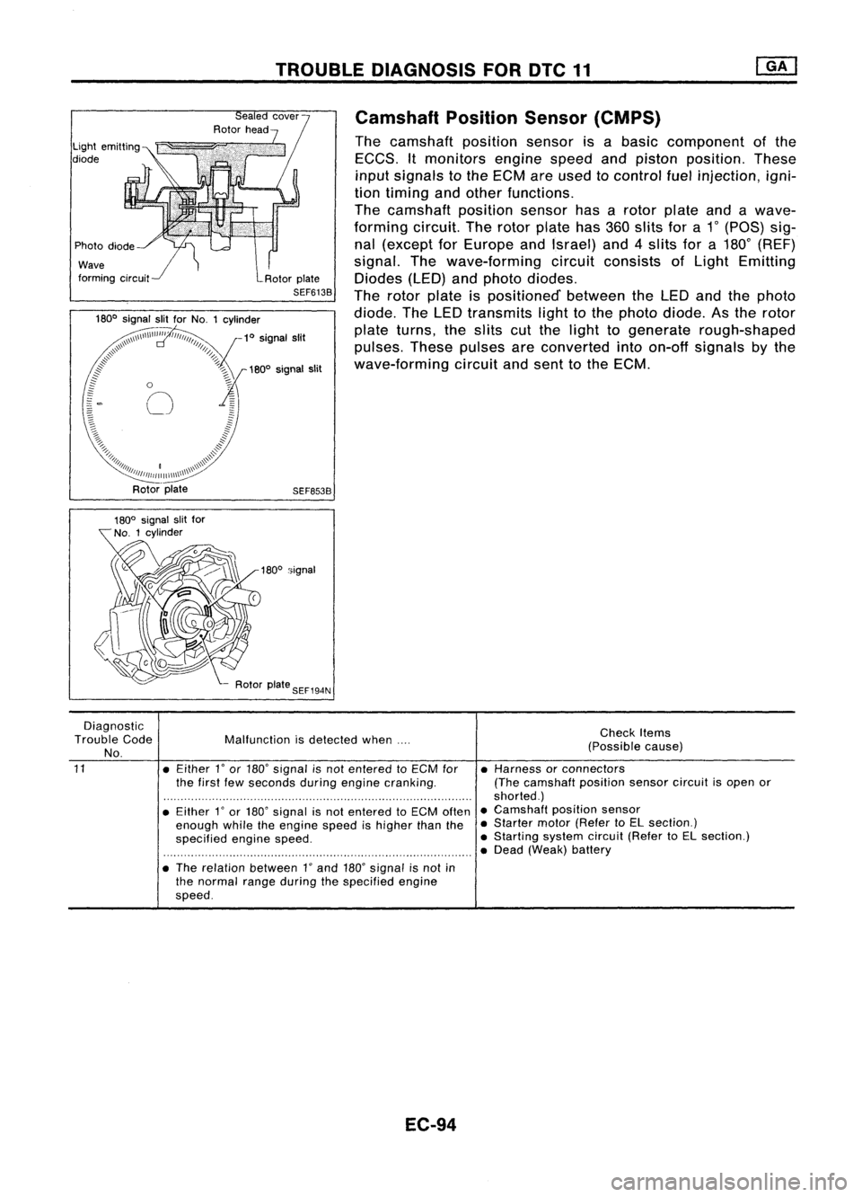
Camshaft
PositionSensor(CMPS)
The camshaft positionsensorisabasic component ofthe
EGGS. Itmonitors enginespeedandpiston position. These
input signals tothe EGM areused tocontrol fuelinjection, igni-
tion timing andother functions.
The camshaft positionsensorhasarotor plate andawave-
forming circuit.Therotor plate has360slits fora1
0
(paS) sig-
nal (except forEurope andIsrael) and4slits fora180
0
(REF)
signal. Thewave-forming circuitconsists ofLight Emitting
Diodes (LED)andphoto diodes.
The rotor plate ispositioned' betweentheLED andthephoto
diode. TheLED transmits lighttothe photo diode. Asthe rotor
plate turns, theslits cutthe light togenerate rough-shaped
pulses. Thesepulses areconverted intoon-off signals bythe
wave-forming circuitandsent tothe EGM.
SEF653B
180
0
signal
Diagnostic
Trouble Code
No.
11
Malfunction
isdetected when....
• Either
l'
or 180' signal isnot entered toECM for
the first fewseconds duringengine cranking.
• Either
l'
or 180' signal isnot entered toECM often
enough whiletheengine speedishigher thanthe
specified enginespeed.
• The relation between
l'
and 180'signal isnot in
the normal rangeduring thespecified engine
speed.
EC-94
Check
Items
(Possible cause)
• Harness orconnectors
(The camshaft positionsensorcircuitisopen or
shorted.)
• Camshaft positionsensor
• Starter motor(Refer toEL section.)
• Starting systemcircuit(RefertoEL section.)
• Dead (Weak) battery
Page 843 of 1701
TROUBLEDIAGNOSIS FOROTC41
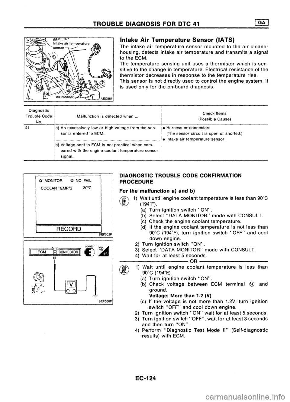
Intake AirTemperature Sensor(IATS)
The intake airtemperature sensormounted tothe aircleaner
housing, detectsintakeairtemperature andtransmits asignal
to the ECM.
The temperature sensingunituses athermistor whichissen-
sitive tothe change intemperature. Electricalresistance ofthe
thermistor decreases inresponse tothe temperature rise.
This sensor isnot directly usedtocontrol theengine system. It
is used onlyforthe on-board diagnosis.
Diagnostic
Trouble Code
No.
41
Malfunction
isdetected when...
a) An excessively loworhigh voltage fromthesen-
sor isentered toECM.
b) Voltage senttoECM isnot practical whencom-
pared withtheengine coolant temperature sensor
signal. Check
Items
(Possible Cause)
• Harness orconnectors
(The sensor circuitisopen orshorted.)
• Intake airtemperature sensor.
*
MONITOR
*
NO FAIL
COOLAN TEMP/S 30°C
RECORD
I
SEF002P
CONNECT ~
II
ECM
a
CONNECTOR
II
I) ~
51
SEF006PDIAGNOSTIC
TROUBLECODECONFIRMATION
PROCEDURE
For themalfunction a)and b)
fF.I\
1)Wait untilengine coolant temperature isless than 90°C
~ (194°F).
(a) Turn ignition switch"ON".
(b) Select "DATA MONITOR" modewithCONSULT.
(c) Check theengine coolant temperature.
(d) Ifthe engine coolant temperature isnot less than
90°C (194°F), turnignition switch"OFF"andcool
down engine.
2) Turn ignition switch"ON".
3) Select "DATA MONITOR" modewithCONSULT.
4) Wait foratleast 5seconds.
---------OR ---------
~ 1)Wait untilengine coolant temperature isless than
~ 90°C(194°F.).
(a) Turn ignition switch"ON".
(b) Check voltage between ECMterminal
@
and
ground.
Voltage: Morethan1.2(V)
(c) Ifthe voltage isnot more than1.2V, turnignition
switch "OFF"andcool down engine.
2) Turn ignition switch"ON"waitforatleast 5seconds.
3) Turn ignition switch"OFF", waitforatleast 3seconds
and then turn"ON".
4) Perform "Diagnostic TestMode II"(Self-diagnostic
results) withECM.
EC-124
Page 847 of 1701
TROUBLEDIAGNOSIS FORNON-DETECTABLE ITEMS
Throttle Position Sensor
The throttle position sensorresponds tothe accelerator pedal
movement. Thissensor isakind ofpotentiometer whichtrans-
forms thethrottle position intooutput voltage, andemits the
voltage signaltothe ECM. Inaddition, thesensor detects the
opening andclosing speedofthe throttle valveandfeeds the
voltage signaltothe ECM.
Idle position ofthe throttle valveisdetermined
by
the ECM
receiving thesignal fromthethrottle position sensor.Thisone
controls engineoperation suchasfuel cut.
SEF089K
CIl
Supplyvoltage:
r
-i.~h __
~3_
i
45
I
'V ,Appl.' b....
ffi
t~miMI,
No1,,'
31
~_ =r--=-tfr ~
I
l ~
1
N~
I
Throttle position sensor g
-g
'5 ::: 0.5
0-
'5
0 0----- -_.- --------_.
OZ 0 90
Throttle valveopening angle(deg_)
EC-128 SEF520Q
Page 855 of 1701
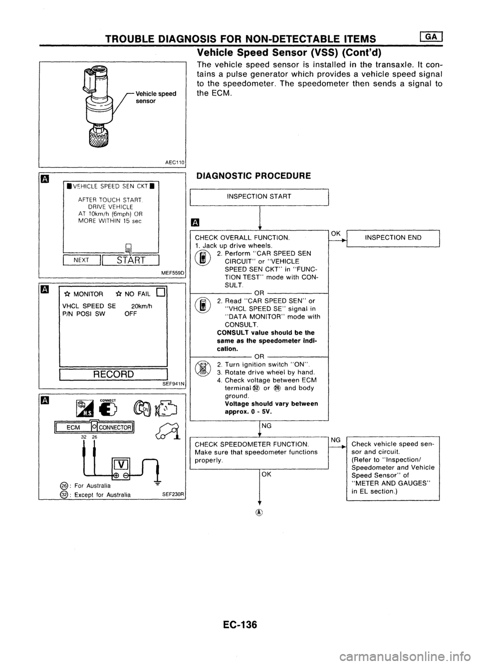
TROUBLEDIAGNOSIS FORNON-DETECTABLE ITEMS
@!J
Vehicle SpeedSensor (VSS)(Conl'd)
The vehicle speedsensor isinstalled inthe transaxle. Itcon-
tains apulse generator whichprovides avehicle speedsignal
to the speedometer. Thespeedometer thensends asignal to
Vehicle speed theECM.
sensor
AEC110 DIAGNOSTIC PROCEDURE
.V~HICLE SPEEDSENCKT.
AFTER TOUCH START.
DRIVE VEHICLE
AT 10km/h (6mph)OR
MORE WITHIN 15
see
INSPECTION
START
SEF941N
-(;(
NO FAIL
0
fijf.....
CONNECT
fIr:J:J:.~
1A1£) ~~
ECM
19'
CONNECTOR
II~
32 26
~l
INSPECTION
END
Check vehicle speedsen-
sor and circuil.
(Refer to"Inspectionl
Speedometer andVehicle
Speed Sensor" of
"METER ANDGAUGES"
in EL section.)
OK
NG
OK
NG
CHECK SPEEDOMETER FUNCTION.
Make surethatspeedometer functions
properly.
CHECK
OVERALL FUNCTION.
1. Jack updrive wheels.
(ij\
2.Perform "CARSPEED SEN
~ CIRCUIT" or"VEHICLE
SPEED SENCKT'" in"FUNC-
TION TEST'" modewithCON-
SULT OR
2. Read "CAR SPEED SEN"'or
"VHCL SPEED SE"signal in
"DATA MONITOR" modewith
CONSULT.
CONSULT valueshould bethe
same asthe speedometer indi-
cation. OR
2. Turn ignition switch"ON".
3. Rotate drivewhe'el byhand.
4. Check voltage between ECM
terminal
@
or@ and body
ground.
Voltage shouldvarybetween
approx. 0-5V.
SEF230R
MEF559D
20km/h
OFF
RECORD
l----
__ ,~--'
-N-EX-T
-II
STA-RT-
-(;( MONITOR
VHCL SPEED SE
PIN POSI SW
@:
ForAustralia
@:
Except forAustralia
II
EC-136
Page 864 of 1701
TROUBLEDIAGNOSIS FORNON-DETECTABLE ITEMS
Fuel Pump
SYSTEM DESCRIPTION
Enginespeed
Camshaft positionsensor
Startsignal
Ignition switch
The ECM activates thefuel pump forseveral sec-
onds aftertheignition switchisturned onto
improve enginestartability. Ifthe ECM receives
a 180
0
signal fromthecamshaft positionsensor,
it knows thattheengine isrotating, andcauses
the pump toperform. Ifthe 180
0
signal isnot
received whentheignition switchison, the
engine stalls.TheECM stops pump operation
and prevents batterydischarging, thereby
improving safety.TheECM does notdirectly
drive thefuel pump. Itcontrols theON/OFF fuel
pump relay, which inturn controls thefuel pump.
ECM
(ECCS
control module)
Condition
Ignition switchisturned toON.
Engine running andcranking
When engine isstopped
Except asshown above Fuel
pump relay
Fuel pump operation
Operates for
5 seconds
Operates
Stops in1second
Stops
•
COMPONENT DESCRIPTION
A turbine typedesign fuelpump isused inthe fuel tank.
AEC801
EC-145