1995 NISSAN ALMERA N15 ESP
[x] Cancel search: ESPPage 322 of 1701

TROUBLEDIAGNOSES
Contents
How toPerform TroubleDiagnoses forQuick andAccurate Repair SR-52
Self-diagnosis SR-53
CONSULT BR-58
CONSULT Inspection Procedure BR-59
Component PartsandHarness Connector Location BR-64
Preliminary Check BR-65
Ground CircuitCheck BR-66
Circuit Diagram forQuick Pinpoint Check BR-67
Diagnostic Procedure1Warning lampdoes notcome on BR-68
Diagnostic Procedure2Warning lampstays on BR-69
Diagnostic Procedure3ABS actuator solenoid valve BR-72
Diagnostic Procedure 4Wheel sensor orrotor BR-74
Diagnostic Procedure5Motor relayormotor BR-76
Diagnostic Procedure6Solenoid valverelay BR-79
Diagnostic Procedure7Power supply BR-81
Diagnostic Procedure 8Control unit BR-82
Diagnostic Procedure9Pedal vibration andnoise BR-82
Diagnostic Procedure10Long stopping distance BR-83
Diagnostic Procedure11Unexpected pedalaction BR-83
Diagnostic Procedure12ABS does notwork BR-84
Diagnostic Procedure13ABS works frequently BR-84
Electrical Component Inspection BR-85
How toPerform TroubleDiagnoses forQuick
and Accurate Repair
INTRODUCTION
The ABS system hasanelectronic controlunittocontrol major
functions. Thecontrol unitaccepts inputsignals fromsensors
and instantly drivestheactuators. Itis essential thatboth kinds
of signals areproper andstable. Itis also important tocheck
for conventional problems:suchasair leaks inbooster lines,
lack ofbrake fluid,orother problems withthebrake system.
SEF233G
Itis much moredifficult todiagnose aproblem thatoccurs
intermittently ratherthancontinuously. Mostintermittent prob-
lems arecaused bypoor electric connections orfaulty wiring.
In this case, careful checking ofsuspicious circuitsmayhelp
prevent thereplacement ofgood parts.
A visual checkonlymaynotfind thecause ofthe problems, so
a road testshould beperformed.
Before undertaking actualchecks, takejustafew minutes to
talk with acustomer whoapproaches withaABS complaint. The
customer isavery good source ofinformation onsuch prob-
lems; especially intermittent ones.Through thetalks withthe
customer, findoutwhat symptoms arepresent andunder what
SEF234G
conditions theyoccur.
Start yourdiagnosis bylooking for"conventional" problems
first. Thisisone ofthe best ways totroubleshoot brakeprob-
lems onanABS controlled vehicle.
BR-52
Page 397 of 1701
SEL711EBATTERY
CAUTION:
• If
itbecomes necessary tostart theengine withabooster
battery andjumper cables, usea12-volt booster battery.
• After connecting batterycables, ensurethatthey aretightly
clamped tobattery terminals forgood contact.
• Never adddistilled waterthrough thehole used tocheck
specific gravity.
How toHandle Battery
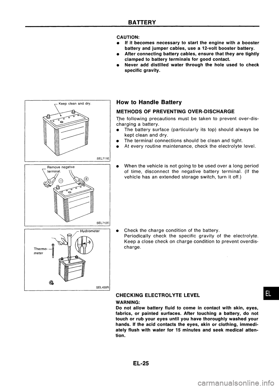
METHODS OFPREVENTING OVER-DISCHARGE
T.he following precautions mustbetaken toprevent over-dis-
charging abattery.
• The battery surface (particularly itstop) should always be
kept clean anddry.
• The terminal connections shouldbeclean andtight.
• Atevery routine maintenance, checktheelectrolyte level.
SEL459R
•
When thevehicle isnot going tobe used overalong period
of time, disconnect thenegative batteryterminal. (Ifthe
vehicle hasanextended storageswitch,turnitoff.)
• Check thecharge condition ofthe battery.
Periodically checkthespecific gravityofthe electrolyte.
Keep aclose check oncharge condition toprevent overdis-
charge.
CHECKING ELECTROLVTELEVEL •
WARNING: Do not allow battery fluidtocome incontact withskin, eyes,
fabrics, orpainted surfaces. Aftertouching abattery, donot
touch orrub your eyes untilyouhave thoroughly washedyour
hands. Ifthe acid contacts theeyes, skinorclothing, immedi-
ately flush withwater for15minutes andseek medical atten-
tion.
EL-25
Page 398 of 1701
BATTERY
How
10
Handle Battery (Coni'd)
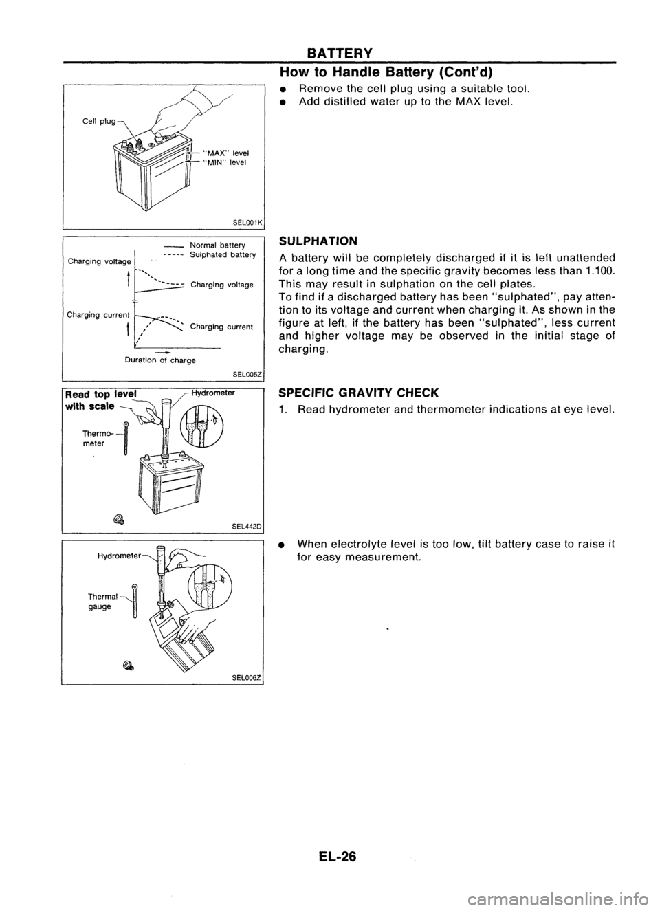
• Remove thecell plug using asuitable tool.
• Add distilled wateruptothe MAX level.
SEL001K
Duration ofcharge
SULPHATION
A battery willbecompletely discharged ifit is left unattended
for along time andthespecific gravitybecomes lessthan 1.100.
This mayresult insulphation onthe cell plates.
To find ifa discharged batteryhasbeen "sulphated", payatten-
tion toits voltage andcurrent whencharging it.As shown inthe
figure atleft, ifthe battery hasbeen "sulphated", lesscurrent
and higher voltage maybeobserved inthe initial stage of
charging.
Charging
voltage
Normal
battery
SUlphated battery
, Charging current
Charging
voltage~_"'"-----
t~
Charging current
t
SEL005Z
Read toplevel
with scale
Hydrometer
Thermal~n gauge ]/
Hydrometer
II~
.' \U)
SEL442DSPECIFIC
GRAVITYCHECK
1. Read hydrometer andthermometer indicationsateye level.
• When electrolyte levelistoo low, tiltbattery casetoraise it
for easy measurement.
SEL006Z
EL-26
Page 401 of 1701
CAPACITYTEST BATTERY
Battery TestandCharging Chart(Cont'd)
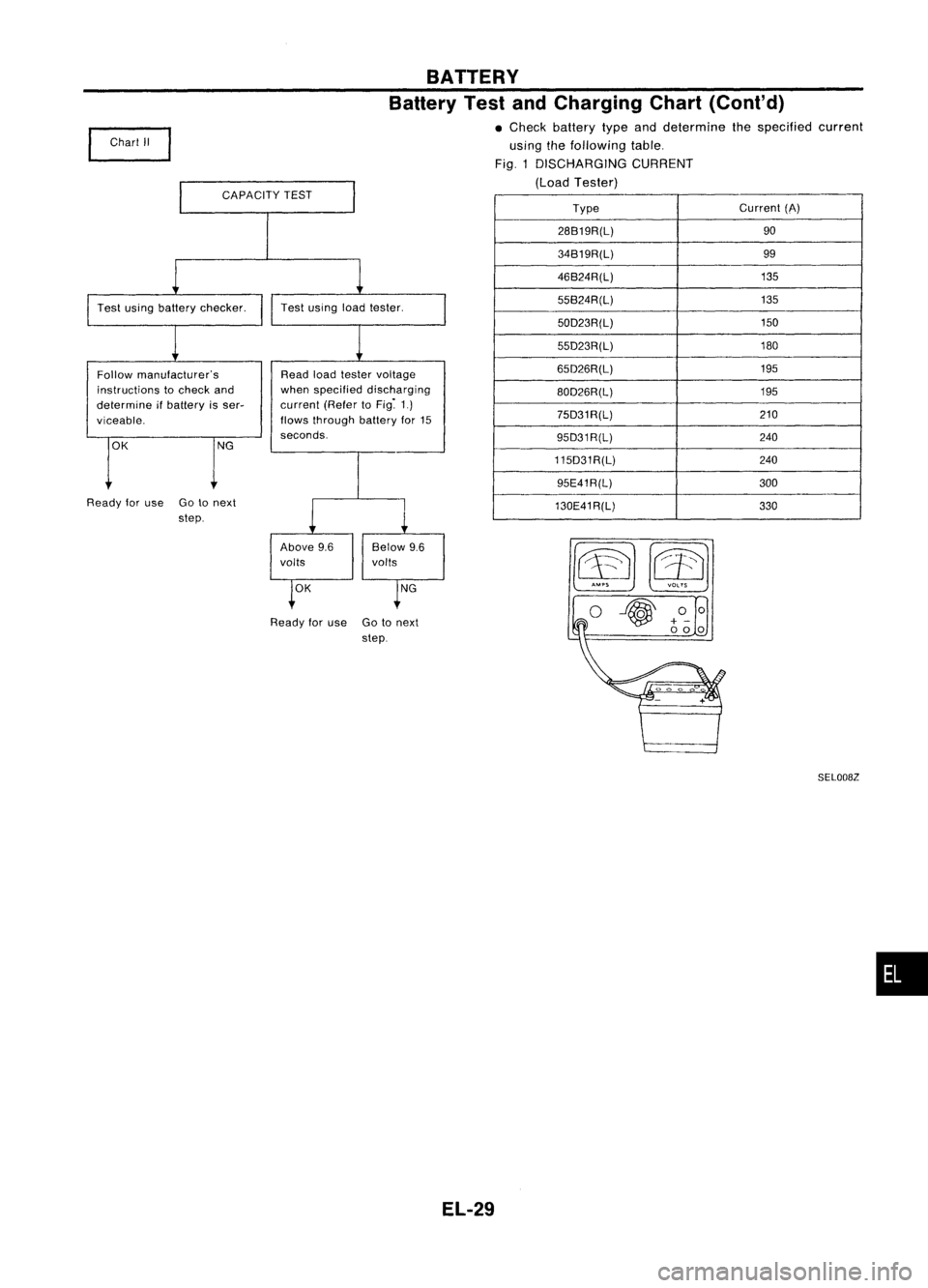
• Check battery typeanddetermine thespecified current
using thefollowing table.
Fig. 1DISCHARGING CURRENT
(Load Tester)
~m o~
Type
Current
(A)
28B19R(L) 90
34B19R(L) 99
46B24R(L) 135
55B24R(L) 135
50D23R(L) 150
55D23R(L) 180
65D26R(L) 195
80D26R(L) 195
75D31R(L) 210
95D31R(L) 240
115D31R(L) 240
95E41R(L) 300
130E41R(L) 330
Test
using loadtester.
OK NG
Read
loadtester voltage
when specified discharging
current (RefertoFig~ 1.)
flows through batteryfor15
seconds.
Above 9.6 Below9.6
volts volts
Ready foruse Gotonext
step.
Chart
II
OK NG
Follow
manufacturer's
instructions tocheck and
determine ifbattery isser-
viceable,
Ready foruse Gotonext
step.
SEL008Z
•
EL-29
Page 402 of 1701
BATTERY
Battery TestandCharging Chart(Cont'd)
I
A: SLOW CHARGE
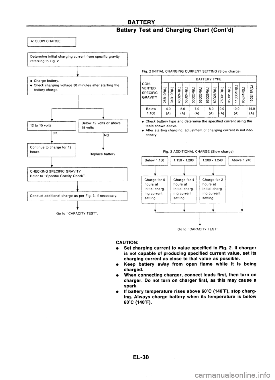
Determine initialcharging currentIromspecilic gravity
relerring toFig. 2.
Fig.2INITIAL CHARGING CURRENTSETTING(Slowcharge)
• Charge battery.
• Check charging voltage30minutes afterstarting the
battery charge. BATTERY
TYPE
CON-
VERTED
2
::J
2
::J
::J
2
::J
2
::J
::J
2
2
::J
if ifif if if
r:r:
if
SPECIFIC
r:r:
r:r: r:r:r:r:r:r:
;;;
r:r:
:;
en en
'
""""
;;;;;;
:;
GRAVITY
~
NNN
NN
N
0
1.U
CD CDCDCD
000 000
to
1.U
0
<0
'
0
to
LO
0
LOLO
~
LO
""
N
""
'
toto
LO
<0
"-
en
~
en
~
Below 4.0
5.07.0
8.09.0 10.0
14.0
1.100 (A)(A)(A) (A)(A)
(A) (A)
• Check battery typeanddetermine thespecified currentusingthe
table shown above.
• After starting charging, adjustment ofcharging currentisnot nec-
essary.
Conduct additional chargeasper Fig. 3.ifnecessary. Fig.
3ADDITIONAL CHARGE(Slowcharge)
Continue
tocharge lor12
hours.
CHECKING SPECIFICGRAVITY
Reier to"Specilic GravityCheck". Replace
battery
Chargefor5
hours at
initial charg-
ing current
selting. Charge
lor4
hours at
initial charg-
ing current
setting. Charge
lor2
hours at
initial charg-
ing current
setting. Above
1.240
Go to"CAPACITY TEST".
I
Go to"CAPACITY TEST"
CAUTION:
• Set charging currenttovalue specified inFig. 2.
If
charger
is not capable ofproducing specifiedcurrentvalue,setits
charging currentasclose tothat value aspossible.
• Keep battery awayfromopen flame whileitis being
charged.
• When connecting charger,connectleadsfirst,thenturnon
charger. Donot turn oncharger first,asthis may cause a
spark.
• If
battery temperature risesabove 60°C(140°F), stopcharg-
ing. Always chargebatterywhenitstemperature isbelow
60°C (140°F).
EL-30
Page 403 of 1701
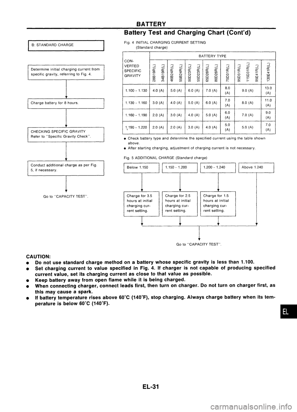
•Check battery typeanddetermine thespecified currentusingthetable shown
above .
• After starting charging, adjustment ofcharging currentisnot necessary.
BATTERY
Battery TestandCharging Chart(Cont'd)
BATTERY TYPE
CON-
VERTED
::J::J
~::J
::J
::J::J ::J ::J
::J
:J
:J
~
SPECIFIC
er:-
er:-
a:
er:-er:- er:-er:- er:- er:- er:-er:-
a:
;:;:;
a:
:;
0> 0> '1"'1"
(')
(')
to to
;:;:;
~
:;
GRAVITY
coco
C'J
C'J C'J
C'JC'J
C'J
(')
D
UJ
co co
DDD D D
D
L!)
UJ
a
to
L!)
a
L!)
L!)
a
L!)
L!)
~
L!)
~
C'J
(')
'1"
L!)
L!)L!)
to
O>
~
OJ
1.100 -1.130 4.0(A) 5.0(A) 60(A) 7.0(A) 8.0
130
(A) 90
(A)
(A)
1.130 -1160 30(Al 4.0(Al 5.0
(A) 6.0(A) 7.0
11.0
(A) 8.0
(A)
(A)
1.160 -1.190 2.0(A) 3.0(Al 4.0
(A)
5.0(Al 6.0
7.0(A) 9.0
(A) (A)
1.190 -1.220 2.0(A) 2.0(A) 3.0(A) 4.0
(A) 5.0
7.0
(A) 5.0
(A)
(A)
Fig. 5ADDITIONAL CHARGE(Standard charge)
Above1240
1.200 -1.240
1.150 -1.200
Below 1.150
Fig.
4INITIAL CHARGING CURRENTSETTING
(Standard charge)
Determine initialcharging currentfrom
specific gravity,referring toFig. 4.
Charge batteryfor8hours.
CHECKING SPECIFICGRAVITY
Refer to"Specific GravityCheck".
Conduct additional chargeasper Fig.
5, ifnecessary.
I
B: STANDARD CHARGE
Go to"CAPACITY TEST". Charge
for3.5
hours atinitial
charging cur-
rent setting. Charge
for2.5
hours atinitial
charging cur-
rent setting. Charge
for1.5
hours atinitial
charging cur-
rent setting.
I
Go to"CAPACITY TEST".
CAUTION:
• Donot use standard chargemethod onabattery whosespecific gravityisless than 1.100.
• Set charging currenttovalue specified inFig. 4.Ifcharger isnot capable ofproducing specified
current value,setitscharging currentasclose tothat value aspossible.
• Keep battery awayfromopen flame whileitis being charged.
• When connecting charger,connectleadsfirst,thenturnoncharger. Donot turn oncharger first,as
this may cause aspark.
• Ifbattery temperature risesabove 60°C(140°F), stopcharging. Alwayschargebatterywhenitstem-
perature isbelow 60°C(140°F).
•
EL-31
Page 404 of 1701
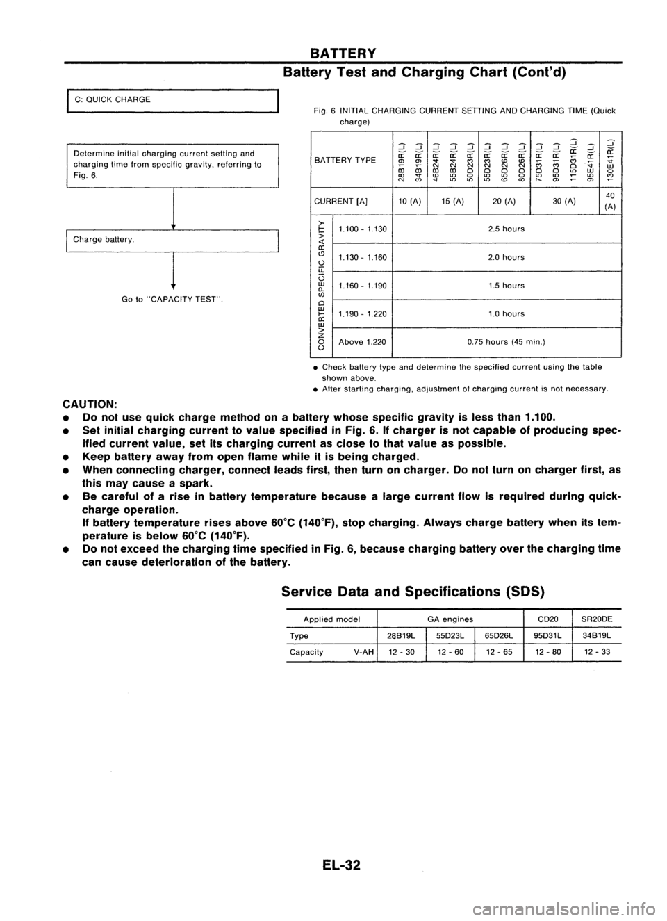
I
C: QUICK CHARGE
Determine initialcharging currentsettingand
charging timefrom specific gravity,referring to
Fig. 6.
I
Charge battery.
Goto"CAPACITY TEST".
BATTERY
Battery TestandCharging Chart(Cont'd)
Fig. 6INITIAL CHARGING CURRENTSETTINGANDCHARGING TIME(Quick
charge)
:::J:::J:::J:::J :::J:::J:::J
d dd
:::J
:::J :::J
~ ~
SA TTERY TYPE
~
~ ~~~~ ~a: a:a:
;;:;
~
~
0>
0>
""
""
C')
C')
CDCD
;;:;
;;:;
~
co co
C\I
N
C\I
N
C\I
N
Cl
W
D:l D:l
ClCl ClCl ClCl
L()
W
0
to
""
CD
L()
0
L()
L()
0
L()
L()
;:
L()
~
N
C')
""
L()
L()L()
CD
to
t-
O>
0>
CURRENT [A]10(A) 15(A) 20(A) 30(A) 40
(A)
>-
I-
1.100 -1.130 2.5
hours
:>
a:
(!J 1.130 -1.160 2.0
hours
0
u::
U
w
1.160 -1.190 1.5hours
0-
w
Cl
w
1.190 -1.220 1.0hours
I-
a:
w
>
z
0
Above 1.220 0.75
hours (45min.)
0
• Check battery typeanddetermine thespecified currentusingthetable
shown above.
• After starting charging, adjustment ofcharging currentisnot necessary.
CAUTION: • Donot use quick charge method onabattery whosespecific gravityisless than 1.100.
• Set initial charging currenttovalue specified inFig. 6.Ifcharger isnot capable ofproducing spec-
ified current value,setitscharging currentasclose tothat value aspossible.
• Keep battery awayfromopen flame whileitis being charged.
• When connecting charger,connectleadsfirst,thenturnoncharger. Donot turn oncharger first,as
this may cause aspark.
• Becareful ofarise inbattery temperature becausealarge current flowisrequired duringquick-
charge operation.
If
battery temperature risesabove 60°C(140°F), stopcharging. Alwayschargebatterywhenitstem-
perature isbelow 60°C(140°F).
• Donot exceed thecharging timespecified inFig. 6,because charging batteryoverthecharging time
can cause deterioration ofthe battery.
Service DataandSpecifications (SOS)
Applied model GA
engines CD20SR20DE
Type 26S19L
55D23L65D26L 95D31L
34S19L
Capacity V-AH
12-30 12
-60 12-65 12-80 12
-33
EL-32
Page 419 of 1701
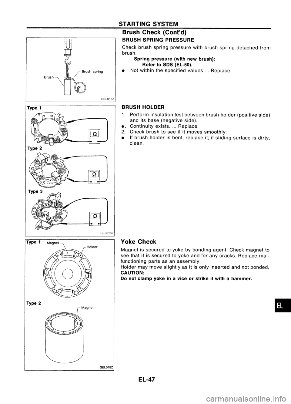
Brush/
Brush spring
SEL015Z STARTING
SYSTEM
Brush Check (Conl'd)
BRUSH SPRING PRESSURE
Check brushspring pressure withbrush spring detached from
brush.
Spring pressure (withnewbrush):
Refer toSOS (EL-50).
e Not within thespecified values...Replace.
Type 1
Type 2
Type 3
SEL016ZBRUSH
HOLDER
1. Perform insulation testbetween brushholder (positive side)
and itsbase (negative side).
e.
Continuity exists....Replace.
2. Check brushtosee ifitmoves smoothly.
e Ifbrush holder isbent, replace it;ifsliding surface isdirty,
clean.
Type 1
Type 2
SEL018ZYoke
Check
Magnet issecured toyoke bybonding agent.Checkmagnet to
see that itis secured toyoke andforany cracks. Replace mal-
functioning partsasan assembly.
Holder maymove slightly asitis only inserted andnotbonded.
CAUTION: Do not clamp yokeinavice orstrike itwith ahammer .
EL-47
•