Page 204 of 1701

__________ PRECAUTIONS ___________
BODYALIGNMENT _
Precautions ForHandling HighStregth Steel Engine
Compartment
__ MEASURMENT POINTS__
Unit:mm
Front side
SBT088
Traction direction: ...
Not
recommended
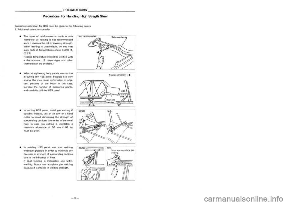
• The repair ofreinforcements (suchasside
members) byheating isnot recommended
since itinvolves theriskoflowering strength.
When heating isunavoidable, donot heat
such parts attemperatures above550°C (1,
022°F)
Heating temperature shouldbeverified with
a thermometer. (Acrayon-type andother
thermometer areavailable.)
• When straightening bodypanels, usecaution
in pulling anyHSS panel. Because itis very
strong, thismay cause deformation inadja-
cent portions ofthe body. Inthis case,
increase thenumber ofmeasuring points,
and carefully pulltheHSS panel.
Special
consideration forHSS must begiven tothe following points:
1 .Additional pointstoconsider
• Incutting HSSpanel, avoidgascutting if
possible. Instead,useanairsaw orahand
cutter toavoid decreasing thestrength of
surrounding portionsduetothe influence of
heat. Incase gascutting isinevitable, a
minimum allowance of50 mm (1.97 in)
must begiven.
SBT090
Radiator
coresupport lower
•
(b)
11
dia.
SBT094
• Inwelding HSSpanel, usespot welding
whenever possibleinorder tominimize any
decrease instrength ofsurrounding portions
due tothe influence ofheat.
If spot welding isimpossible, useM.LG.
welding. Donotuseacetylene gaswelding
because itis inferior inwelding strength.
GOOD
-================
N.G.
Never useacetylene .gas
welding.
Radiator
coresupport uppercenter
SBT091
-29-
-16-
Page 206 of 1701

__________ PRECAUTIONS _
_ BODYALIGNMENT _
Precautions ForHandling HighStrength Steel
PanelPartsMatching Marks
~ViewE
3-Door Hatchback
and 5-Door Hatchback
A
mark hasbeen placed oneach partofthe body toindicate thepanel partsmatching positions.Whenrepairing
parts damaged byan accident whichmightaffectthevehicle frame(members, pillars,etc.)more accurate,
effective repairwillbepossible byusing these marks together wi~hbody alignment data.
Welding
current
Pressure
Unit:mrr
(C•
Thickness
(t)
Minimum pitch(
Q )
0.6 (0.024)
I
10 (0.39)
orover
0.8 (0.031) 12(0.47)
orover
1.0 (0.039) 18(0.71)
orover
1.2 (0.047) 20(0.79)
orover
1.6 (0.063) 27(1.06)
orover
~71) 31
11.221
orover
•
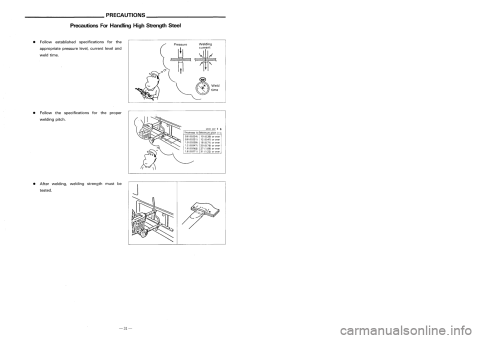
Follow established specifications forthe
appropriate pressurelevel,current leveland
weld time.
• Follow thespecifications forthe proper
welding pitch.
• After welding, weldingstrength mustbe
tested.
J
Type
W:
@----- ~
Et
Type V:~----- ~
View A ViewS
ViewC
View D-1 View
D-2
ViewE
Sedan and5-door Hatchback 3-door
Hatchback
3-door
Hatchback and5-door Hatchback
/w-..IE
+-W
II (-
'- r )
o
-31- -14-
Page 223 of 1701
GENERALSERVICING
Clip andFastener
Removal
&
Installation
Shapes
•
Clips andfasteners inBT section correspond tothe following numbersandsymbols.
• Replace anyclips and/or fasteners whicharedamaged duringremoval orinstallation.
Symbol
No.
Removal:
Remove bybending upwith
flat -bladed screwdrivers or
clip remover.
SBF302H SBF367BA
@D
T1f1f~,Q
9
Removal:
Remove withaclip remover.
SBT095 SBF423H
f
Removal:
@ID
~s""ru'
u
w
l1!
y
Finisher
MBF518B SBF638C
•
@D
,
MBF519BMBF520B
81-3
Page 254 of 1701
EXTERIOR
@
Rear airspoiler
• When installing, makesurethatthere arenotgaps orwaves atends ofair spoiler.
• Before installing spoiler,cleanandremove oilfrom surface wherespoiler willbemounted.
4-door sedan
SEC. 960
Sealingrubber
SBT075
3-door and5-door hatchback
SEC. 960
8T-34
Double-laced
adhesivelape
SBT076
Page 293 of 1701

Pistonbootretainer (AD22VF only)
Piston boot
Piston seal
FRONT
DISCBRAKE
Inspection -Caliper (Cont'd)
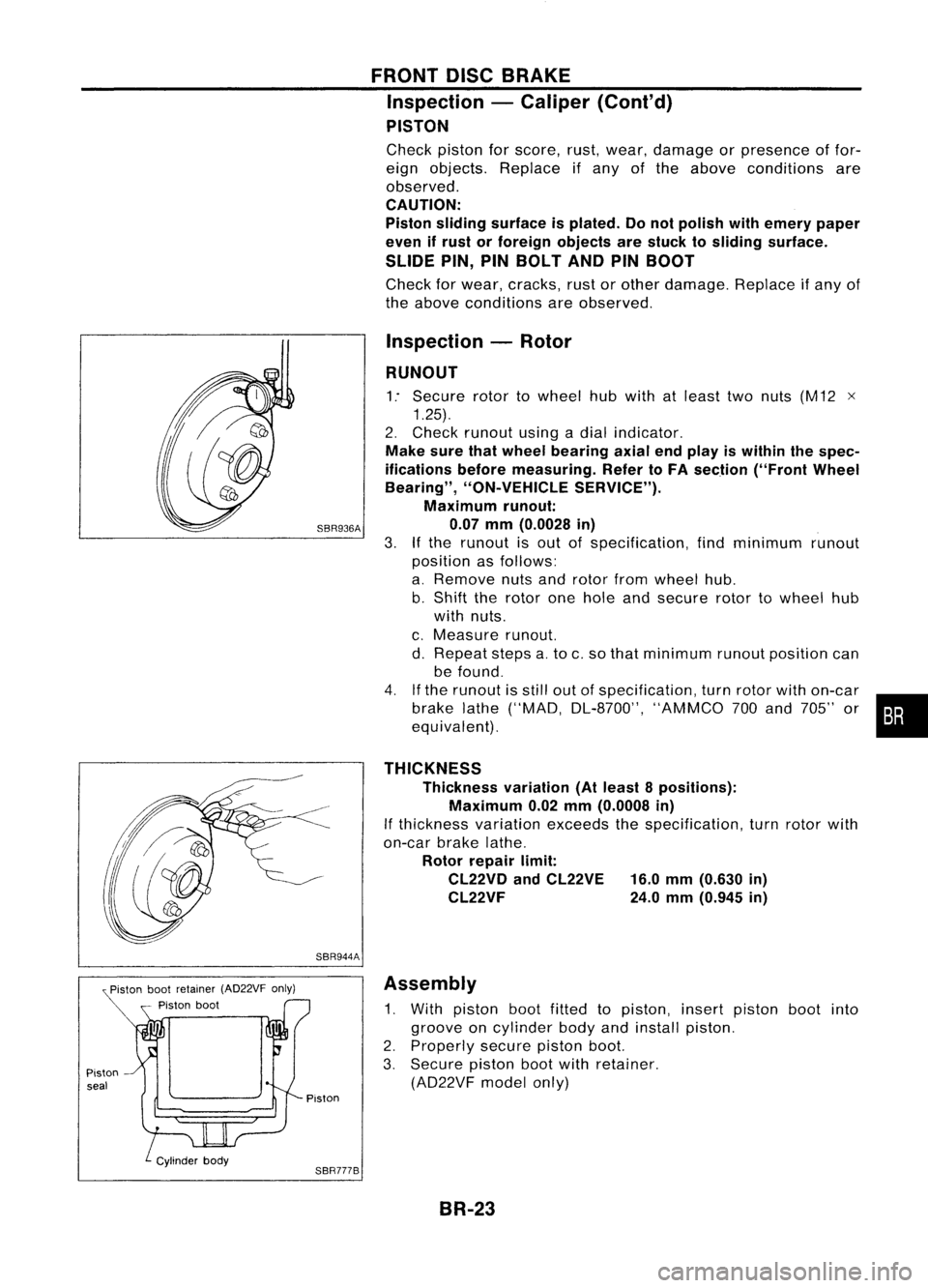
PISTON
Check pistonforscore, rust,wear, damage orpresence offor-
eign objects. Replace ifany ofthe above conditions are
observed.
CAUTION:
Piston sliding surface isplated. Donot polish withemery paper
even ifrust orforeign objects arestuck tosliding surface.
SLIDE PIN,PINBOLT ANDPINBOOT
Check forwear, cracks, rustorother damage. Replaceifany of
the above conditions areobserved.
Inspection -Rotor
RUNOUT
1: Secure rotortowheel hubwith atleast twonuts (M12 x
1.25).
2. Check runout usingadial indicator.
Make surethatwheel bearing axialendplay iswithin thespec-
ifications beforemeasuring. RefertoFA section ("FrontWheel
Bearing", "ON-VEHICLE SERVICE").
Maximum runout:
SBR936A 0.07mm(0.0028 in)
3.
If
the runout isout ofspecification, findminimum runout
position asfollows:
a. Remove nutsandrotor fromwheel hub.
b. Shift therotor onehole andsecure rotortowheel hub
with nuts.
c. Measure runout.
d. Repeat stepsa.to c.so that minimum runoutposition can
be found.
4. Ifthe runout isstill outofspecification, turnrotor withon-car
brake lathe("MAD, DL-8700", "AMMCO700and 705" or•••
equivalent).
THICKNESS Thickness variation(Atleast 8positions):
Maximum 0.02mm(0.0008 in)
If thickness variationexceedsthespecification, turnrotor with
on-car brakelathe.
Rotor repair limit:
CL22VD andCL22VE 16.0mm(0.630 in)
CL22VF 24.0mm(0.945 in)
SBR944A Assembly
1. With piston bootfitted topiston, insertpiston bootinto
groove oncylinder bodyandinstall piston.
2. Properly securepistonboot.
3. Secure pistonbootwithretainer.
(AD22VF modelonly)
Piston
SBR777B BR-23
Page 296 of 1701
Bolts
(M8
x
1.25) Wheel
cylinder
Adjuster
SBR280B
SBR020A REAR
DRUM BRAKE
Removal (Cont'd)
1. Release parkingbrakeleverfully,thenremove drum.
If drum ishard toremove, thefollowing procedures shouldbe
carried out.
a. Remove plug.Thenshorten adjuster tomake clearance
between brakeshoeanddrum asshown.
b. Tighten thetwo bolts gradually.
SBR785BA
2.
After removing retainer,removespringbyrotating shoes.
• Becareful nottodamage wheelcylinder pistonboots.
• Becareful nottodamage parkingbrakecablewhensepa-
rating it.
3. Remove adjuster.
4. Disconnect parkingbrakecablefromtoggle lever.
5. Remove retainerringwith asuitable tool.Then separate
toggle leverandbrake shoe.
Inspection -Wheel Cylinder
• Check wheelcylinder forleakage.
• Check forwear, damage andloose conditions.
Replace ifany such condition exists.
BR-26
Page 303 of 1701
SBR847
SBR247B REAR
DISCBRAKE
Inspection -Rotor
RUBBING SURFACE
Check rotorforroughness, cracksorchips.
RUNOUT
1. Secure rotortowheel hubwith atleast twonuts (M12 x1.25).
2. Check runout usingadial indicator.
Make surethatwheel bearing axialendplay iswithin thespec-
ifications beforemeasuring. Referto"Rear Wheel Bearing" of
"ON-VEHICLE SERVICE"inRA section.
3. Change relativepositions ofrotor andwheel hubsothat
runout isminimized.
Maximum runout:
0.07 mm(0.0028 in)
THICKNESS Rotor repair limit:
Minimum thickness
CL7HB 6.0mm (0.236 in)
CL9HC 8.0mm (0.315 in)
Thickness variation(Atleast 8portions)
Maximum 0.02mm(0.0008 in)
Replace rotorifany ofthe above donot meet thespecifications .
Assembly
1. Insert camwithdepression facingtowards openendofcyl-
inder.
2. Generously applyrubber grease tostrut andpush rodto
make insertion easy.
BR-33
•
Page 314 of 1701
ANTI-LOCKBRAKESYSTEM
Removal andInstallation (Cont'd)
10. Draw outASS actuator asshown.
ASS
actuator
SBR039D CAUTION:
After installation, payattention tothe following points:
• Refill brake fluidandbleed air.Refer to"CHECK AND
ADJUSTMENT", BR-5and"AIR BLEEDING", BR.6,respec-
tively.
• Charge airconditioner refrigerant.RefertoHA section,
("R-134a ServiceProcedure", "SERVICEPROCEDURES").
• The installation procedureisthe reverse ofremoval.
ASS
actuator
_-=--=--=--=--_-_-\,_~
""'~t"
b"ok.,
SBR040D
ABSRELAYS
1. Disconnect batterycable.
2. Remove ASSrelay cover.
BR-44