1995 NISSAN ALMERA N15 ESP
[x] Cancel search: ESPPage 91 of 1701
REPAIRFORCOMPONENT PARTS
Control ValveLower Body(Cont'd)
DISASSEMBL Y
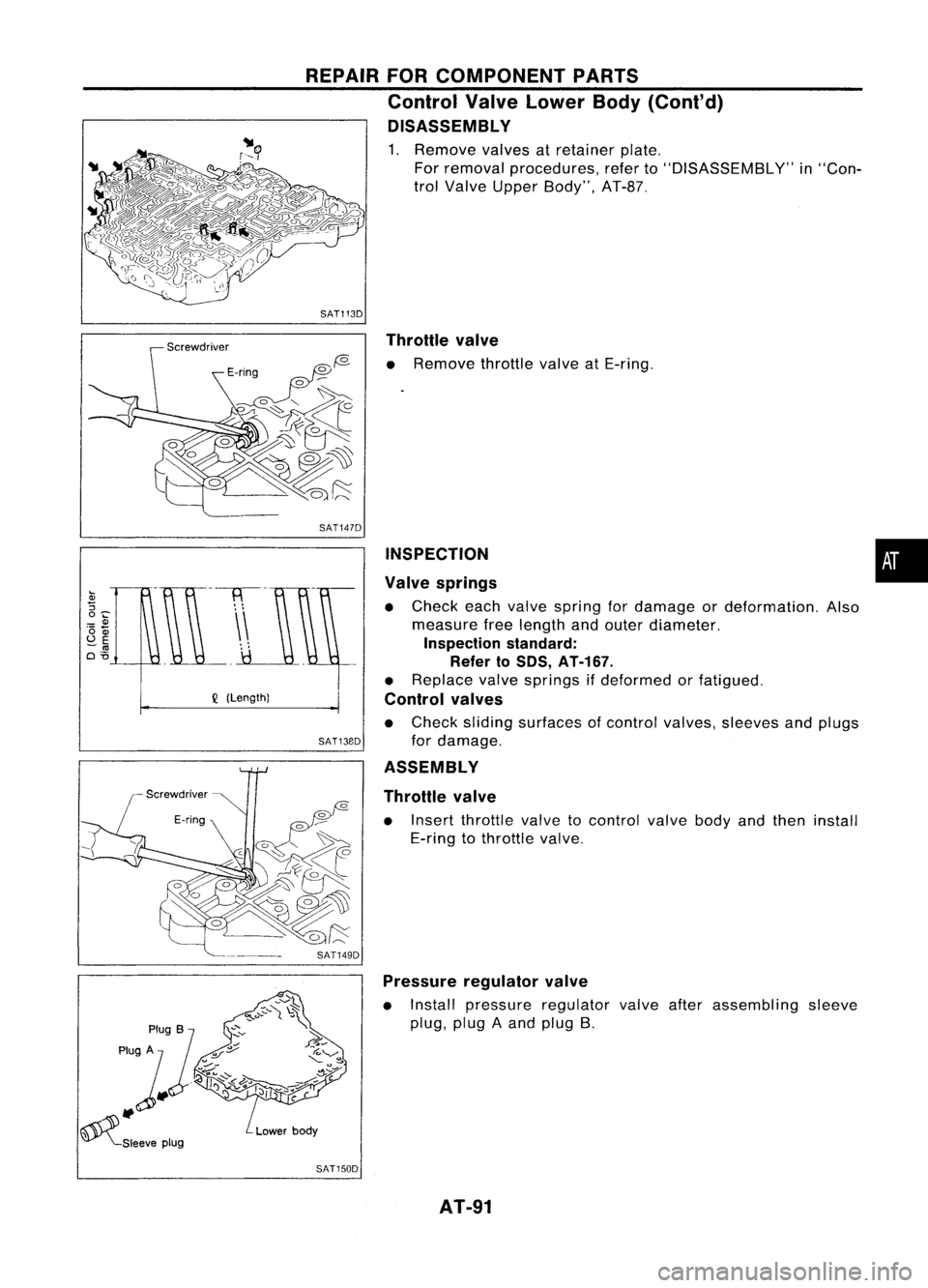
1. Remove valvesatretainer plate.
For removal procedures, referto"DISASSEMBLY" in"Con-
trol Valve Upper Body", AT-B?
SAT1130 Throttle valve
o
f2- •
Remove throttlevalveatE-ring.
•
INSPECTION
Valve springs
• Check eachvalve spring fordamage ordeformation. Also
measure freelength andouter diameter.
Inspection standard:
Refer to50S, AT-167.
• Replace valvesprings ifdeformed orfatigued.
Control valves
• Check sliding surfaces ofcontrol valves, sleeves andplugs
for damage.
ASSEMBLY
Throttle valve
• Insert throttle valvetocontrol valvebodyandthen install
E-ring tothrottle valve.
SAT147D
SAT13BO
Q
(Length)
SAT1490Pressure regulator valve
• Install pressure regulator valveafterassembling sleeve
plug, plugAand plug B.
SAT1500 AT-91
Page 93 of 1701
REPAIRFORCOMPONENT PARTS
Reverse Clutch
Piston
* :
Select proper thickness.
~. ApplyATF.
Oil
seal~@D
D-ring~
@:>
Snap ring~
Dish
plate
Drive plate
SEC.
315
Retaining plate
*
Snap ring
I
Driven plate
Snap ring~
SAT940HA
DISASSEMBLY •
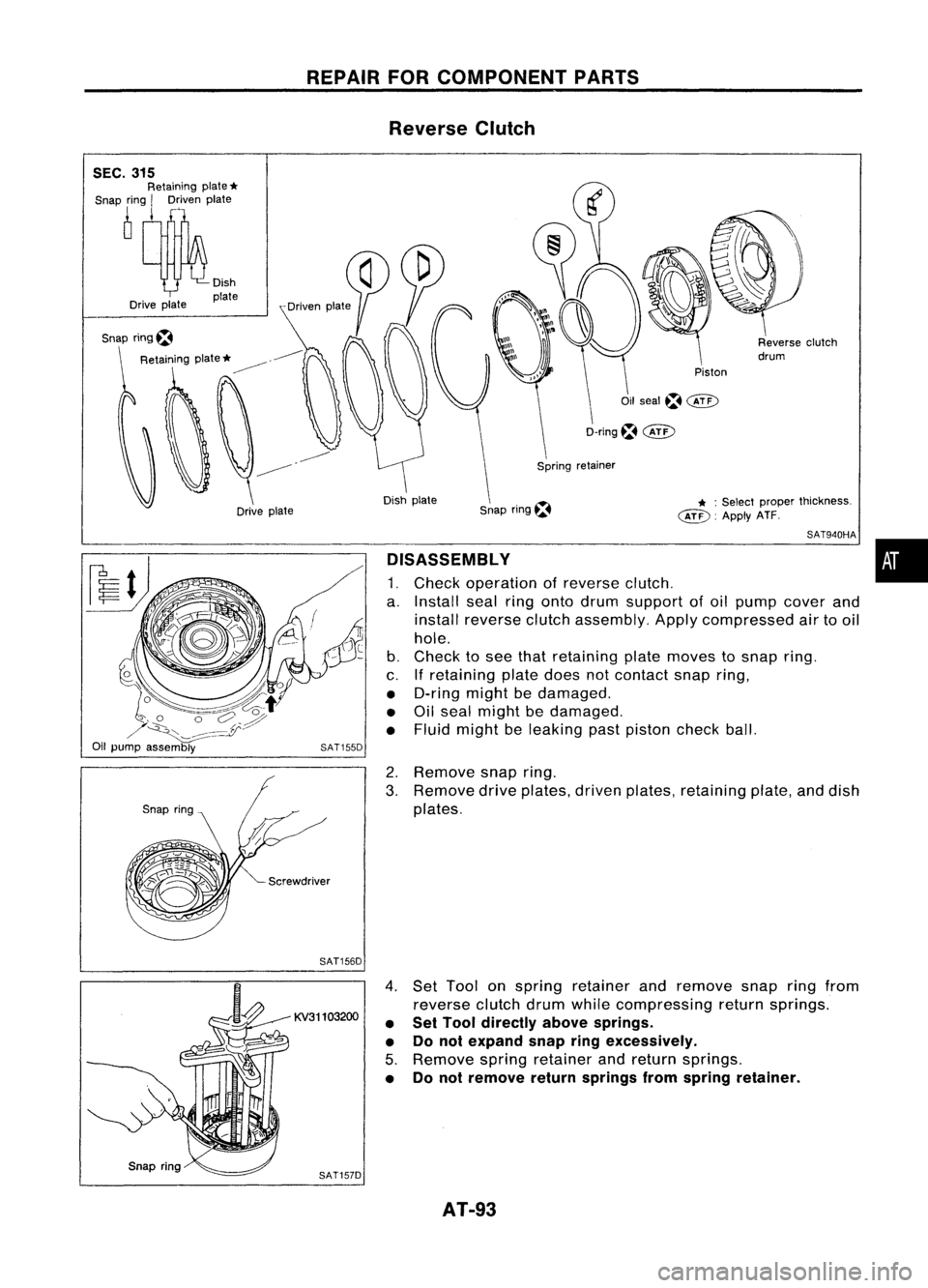
1. Check operation ofreverse clutch.
a. Install sealringonto drum support ofoil pump cover and
install reverse clutchassembly. Applycompressed airtooil
hole.
b. Check tosee that retaining platemoves tosnap ring.
c. Ifretaining platedoesnotcontact snapring,
• D-ring mightbedamaged.
• Oilseal might bedamaged.
• Fluid might beleaking pastpiston checkball.
2. Remove snapring.
3. Remove driveplates, drivenplates, retaining plate,anddish
plates.
SAT156D
KV31103200
SAT157D
4.
Set Tool onspring retainer andremove snapringfrom
reverse clutchdrumwhilecompressing returnsprings.
• Set Tool directly abovesprings.
• Donot expand snapringexcessively.
5. Remove springretainer andreturn springs.
• Donot remove returnsprings fromspring retainer.
AT-93
Page 98 of 1701
Snapring,
REPAIR
FORCOMPONENT PARTS
High Clutch (Cont'd)
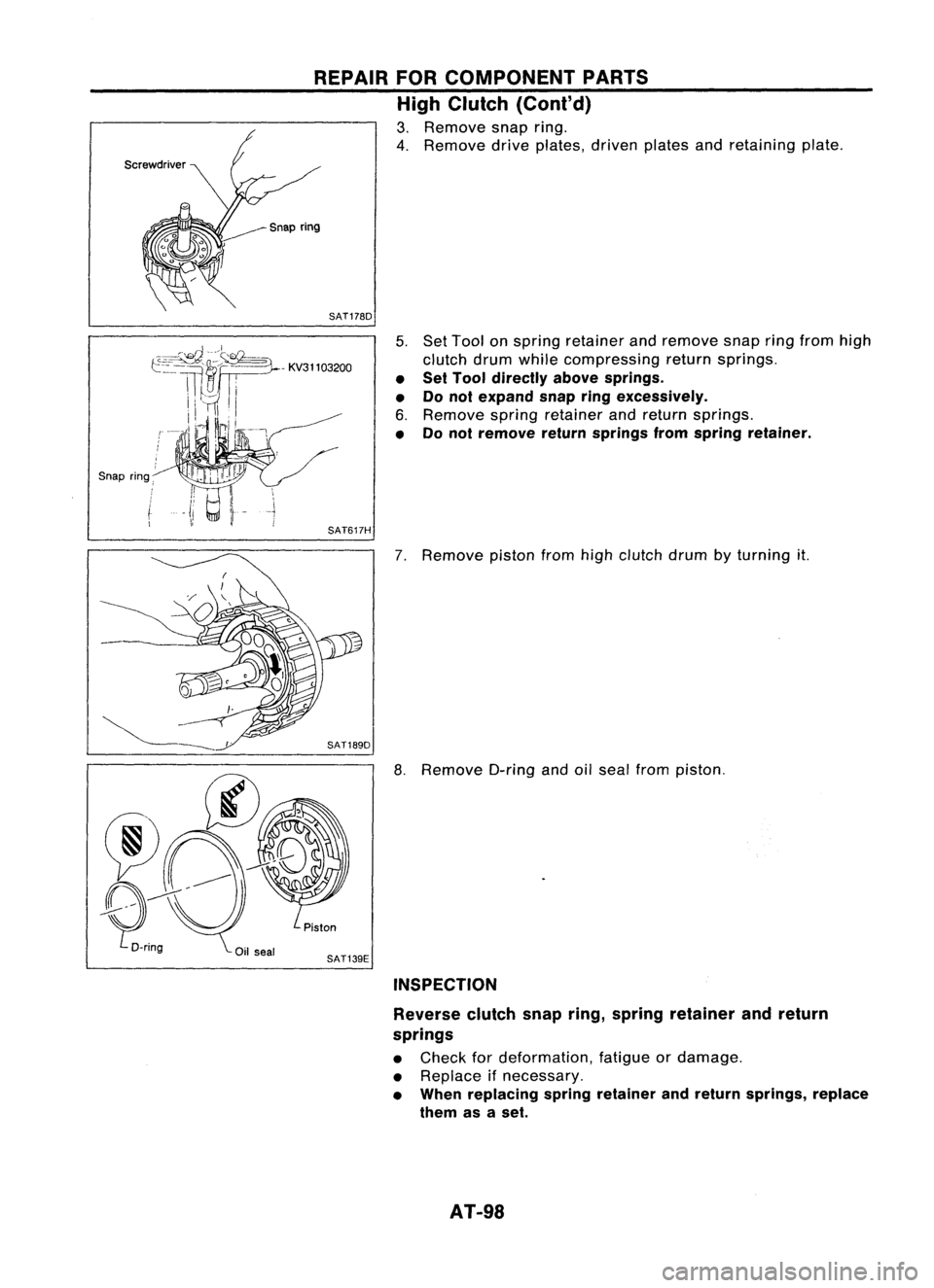
3. Remove snapring.
4. Remove driveplates, drivenplatesandretaining plate.
SAT178D
5.Set Tool onspring retainer andremove snapringfrom high
clutch drumwhile compressing returnsprings.
• Set Tool directly abovesprings.
• Donot expand snap
ring
excessively.
6. Remove springretainer andreturn springs.
• Donot remove returnsprings fromspring retainer.
SAT617H
7.Remove pistonfromhighclutch drumbyturning it.
8. Remove O-ringandoilseal from piston.
SAT139E INSPECTION
Reverse clutchsnapring,spring retainer andreturn
springs
• Check fordeformation, fatigueordamage.
• Replace ifnecessary.
• When replacing springretainer andreturn springs, replace
them asaset.
AT-98
Page 166 of 1701
Vehiclespeed
km/h (MPH)
Gear position
Throttle position
SERVICE
OATAAND SPECIFICATIONS (SOS)
Specifications andAdjustments (Cont'd)
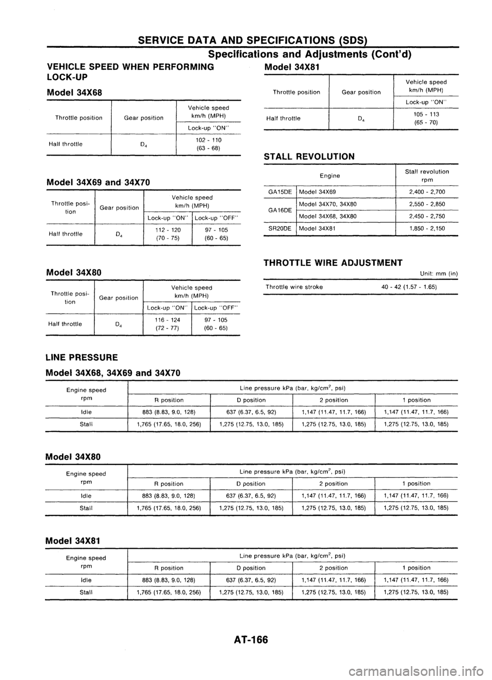
VEHICLE SPEEDWHENPERFORMING Model34X81
LOCK-UP
Model 34X68
Throttle position
Half throttle Gear
position Vehicle
speed
km/h (MPH)
Lock-up "ON"
102 -110
(63 -68)
Half
throttle
STALL REVOLUTION
Lock-up
"ON"
105 -113
(65 -70)
Model 34X69and34X70
Vehiclespeed
Throttle posi-
Gearposition km/h
(MPH)
tion
Lock-up"ON"Lock-up "OFF"
Half throttle
D
4
112
-120 97-105
(70 -75)
(60-65) Engine
Stall
revolution
rpm
GA15DE Model34X69 2,400
-2,700
Model 34X70, 34X80 2,550-2,850
GA16DE Model34X68, 34X80 2,450
-2,750
SR20DE Model
34X81 1,850-2,150
THROTTLE WIREADJUSTMENT
Model 34X80
Unit:mm(in)
Vehicle speed
Throttle posi-
Gearposition km/h
(MPH)
tion Lock-up"ON"Lock-up "OFF"
Half throttle
D
4
116
-124 97-105
(72 -77) (60
-65) Throttle
wirestroke 40-42 (1.57 -1.65)
LINE PRESSURE
Model 34X68, 34X69and34X70
Engine speed Line
pressure kPa(bar, kg/em', psi)
rpm Rposition Dposition 2position 1position
Idle 883(8.83, 9.0,128) 637
(6.37, 6.5,92) 1,147(11.47,11.7,166) 1,147(11.47,11.7,166)
Stall 1,765(17.65, 18.0,256) 1,275(12.75,13.0,185) 1,275(12.75, 13.0,185) 1,275
(12.75,13.0,185)
Model 34X80
Engine speed Line
pressure kPa(bar, kg/em?, psi)
rpm Rposition Dposition 2
position 1position
Idle 883(8.83, 9.0,128) 637(6.37, 6.5,92) 1,147
(11.47,11.7,166) 1,147
(11.47,11.7,166)
Stall 1,765
(17.65, 18.0,256) 1,275(12.75, 13.0,185) 1,275(12.75, 13.0,185) 1,275
(12.75, 13.0,185)
Model 34X81
Engine speed Line
pressure kPa(bar, kg/em', psi)
rpm Rposition Dposition 2position 1
position
Idle 883(8.83, 9.0,128) 637(6.37, 6.5,92) 1,147
(11.47,11.7,166) 1,147
(11.47,11.7,166)
Stall 1,765
(17.65, 18.0,256) 1,275(12.75, 13.0,185) 1,275(12.75, 13.0,185) 1,275
(12.75, 13.0,185)
AT-166
Page 167 of 1701
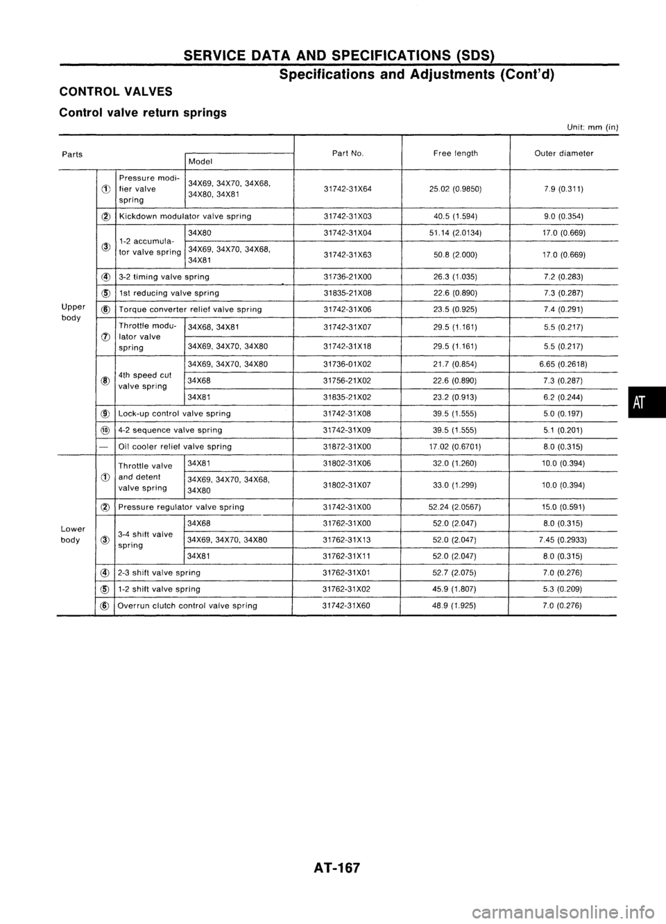
SERVICEDATAANDSPECIFICATIONS (SOS)
Specifications andAdjustments (Cont'd)
CONTROL VALVES
Control valvereturn springs
Unit:
mm
(in)
Parts Part
No. Freelength
Outerdiameter
Model
Pressure modi-
34X69,34X70, 34X68,
d)
liervalve 31742-31X642502(0.9850) 79(0.311)
spring 34X80,
34X81
@)
Kickdown
modulator valvespring 31742-31X03 40.5(1.594) 9.0(0.354)
34X80 31742-31X0451.14(2.0134) 17.0(0.669)
@
1-2
accumula-
tor valve spring 34X69,
34X70,34X68,
34X81 31742-31X63
50.8(2000) 17.0(0.669)
@
3-2timing valvespring 31736-21
XOO 26.3(1.035) 7.2(0.283)
~ 1st
reducing valvespring 31835-21X0822.6(0.890) 7.3(0.287)
Upper
@
Torque converter reliefvalve spring 31742-31X06 23.5(0.925) 7.4(0.291)
body Throttlemodu-
34X68,34X81
31742-31X07 29.5
(1.161)
5.5(0.217)
(J)
lator valve
spring 34X69,
34X70, 34X80 31742-31X18 29.5(1161)
5.5(0.217)
34X69, 34X70, 34X80 31736-01X02 21.7(0.854) 6.65(0.2618)
@
4th
speed cut
34X68 31756-21X0222.6(0.890)
7.3(0.287)
valve spring
34X81 31835-21X0223.2(0913) 6.2(0.244)
@
Lock-up
controlvalvespring 31742-31X08
39.5(1.555) 50(0.197)
@
4-2sequence valvespring 31742-31X0939.5(1.555) 51(0.201)
-
Oilcooler reliefvalve spring 31872-31XOO17.02(0.6701) 8.0(0.315)
Throttle valve 34X81
31802-31X06 32.0(1.260) 10.0(0.394)
d)
anddetent
34X69,34X70, 34X68,
valve spring
34X80 31802-31X07
33.0
(1.299)
10.0(0.394)
(2)
Pressure regulatorvalvespring 31742-31XOO 5224(2.0567) 15.0(0.591)
Lower 34X68
31762-31XOO
52.0(2.047)
8.0(0.315)
body
@
3-4
shift valve
34X69,34X70,34X80 31762-31X13 52.0(2.047) 7.45(0.2933)
spring
34X81 31762-31X1152.0(2.047) 80(0.315)
@
2-3shift valve spring 31762-31X0152.7(2.075) 7.0(0.276)
cID
1-2
shift valve spring 31762-31X0245.9(1.807) 5.3(0.209)
@
Overrun clutchcontrol valvespring 31742-31X60 48.9
(1.925) 7.0(0.276)
AT-167
•
Page 173 of 1701
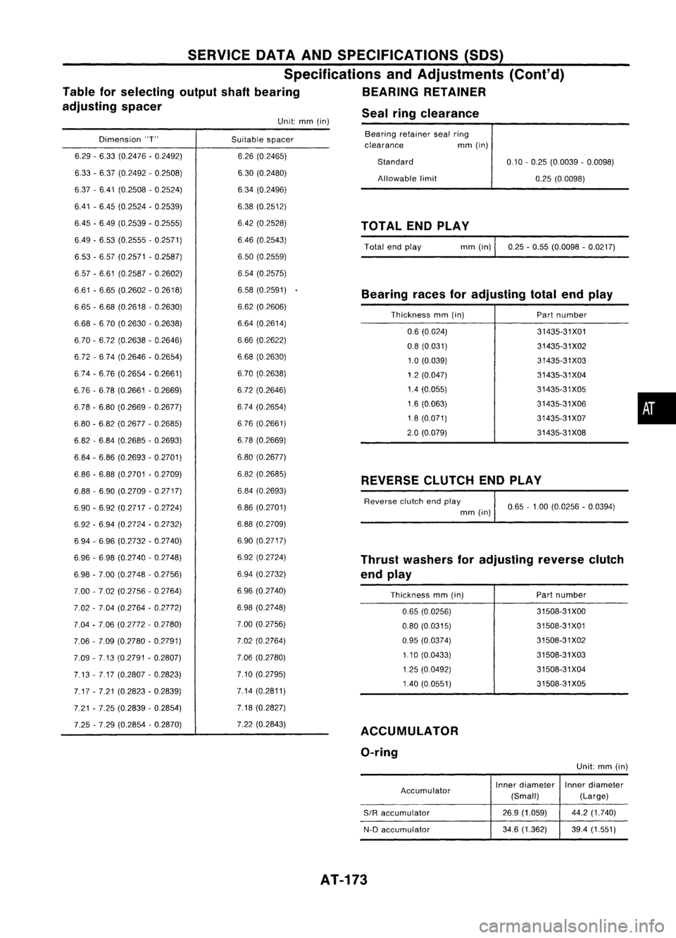
Sealringclearance
Unit: mm(in)
SERVICE
DATAANDSPECIFICATIONS (SOS)
Specifications andAdjustments (Cont'd)
Table forselecting outputshaftbearing BEARINGRETAINER
adjusting spacer
Dimension "T" Suitablespacer Bearing
retainersealring
clearance mm(in)
REVERSE CLUTCHENDPLAY
Bearing
racesforadjusting totalendplay
Thrust washers foradjusting reverseclutch
end play
Thickness mm(in)
•
31435-31X01
31435-31X02
31435-31X03
31435-31X04
31435-31 X05
31435-31X06
31435-31X07
31435-31X08
31508-31XOO
31508-31X01
31508-31 X02
31508-31X03
31508-31X04
31508-31X05
Part
number
Part number
0.65
-1.00 (0.0256 -0.0394)
0.10
-0.25 (0.0039 -0.0098)
0.25 (0.0098)
mm (in)
0.25-0.55 (0.0098 -0.0217)
0.6 (0024)
0.8 (0.031)
1.0 (0.039)
1.2 (0.047)
1.4 (0.055)
1.6 (0.063)
1.8 (0.071)
2.0 (0.079)
0.65 (0.0256)
0.80 (00315)
0.95 (0.0374)
1.10 (0.0433)
1.25 (0.0492)
1.40 (0.0551)
Thickness
mm(in)
Allowable
limit
Standard
Total endplay
Reverse clutchendplay
mm (in)
TOTAL
ENDPLAY
ACCUMULATOR O-ring
6.26
(0.2465)
6.30 (0.2480)
634 (0.2496)
6.38 (0.2512)
6.42 (0.2528)
6.46 (0.2543)
6.50 (0.2559)
654 (0.2575)
6.58 (0.2591)
6.62 (0.2606)
6.64 (0.2614)
6.66 (0.2622)
6.68 (0.2630)
6.70 (0.2638)
6.72 (0.2646)
6.74 (0.2654)
676 (0.2661)
6.78 (0.2669)
6.80 (0.2677)
6.82 (0.2685)
6.84 (0.2693)
6.86 (0.2701)
6.88 (0.2709)
690 (0.2717)
6.92 (0.2724)
6.94 (0.2732)
696 (0.2740)
6.98 (0.2748)
7.00 (0.2756)
7.02 (0.2764)
7.06 (0.2780)
7.10 (0.2795)
7.14 (0.2811)
7.18 (0.2827)
7.22 (0.2843)
6.29
-6.33 (0.2476 -0.2492)
6.33 -6.37 (0.2492 -0.2508)
6.37 -6.41 (0.2508 -0.2524)
6.41 -6.45 (0.2524 -0.2539)
6.45 -6.49 (0.2539 -0.2555)
6.49 -6.53 (0.2555 -0.2571)
6.53 -657 (0.2571 -0.2587)
6.57 -6.61 (0.2587 -0.2602)
6.61 -6.65 (0.2602 -0.2618)
6.65 -668 (0.2618 -0.2630)
6.68 -670 (0.2630 -0.2638)
6.70 -6.72 (0.2638 -0.2646)
6.72 -674 (0.2646 -0.2654)
6.74 -6.76 (0.2654 -0.2661)
6.76 -6.78 (0.2661 -0.2669)
6.78 -6.80 (0.2669 -0.2677)
6.80 -6.82 (0.2677 -0.2685)
6.82 -684 (0.2685 -0.2693)
6.84 -6.86 (0.2693 -0.2701)
6.86 -6.88 (0.2701 -0.2709)
6.88 -6.90 (0.2709 -0.2717)
6.90 -6.92 (0.2717 -0.2724)
6.92 -6.94 (0.2724 -0.2732)
6.94 -696 (0.2732 -0.2740)
6.96 -698 (0.2740 -0.2748)
6.98 -7.00 (0.2748 -0.2756)
7.00 -702 (0.2756 -02764)
7.02 -7.04 (0.2764 -0.2772)
7.04 -7.06 (0.2772 -0.2780)
7.06 -7.09 (0.2780 -0.2791)
7.09 -7.13 (0.2791 -0.2807)
7.13 -7.17 (0.2807 -0.2823)
7.17 -7.21 (0.2823 -0.2839)
7.21 -7.25 (0.2839 -0.2854)
7.25 -7.29 (0.2854 -0.2870)
Unit:mm(in)
Accumulator Inner
diameter Innerdiameter
(Small) (Large)
SIR
accumulator
26.9
(1.059) 44.2(1.740)
N-D accumulator
34.6
(1.362) 39.4(1.551)
AT-173
Page 189 of 1701
__________ PRECAUTIONS _
_ BODYALIGNMENT _
Precautions ForHandling HighStrength Steel
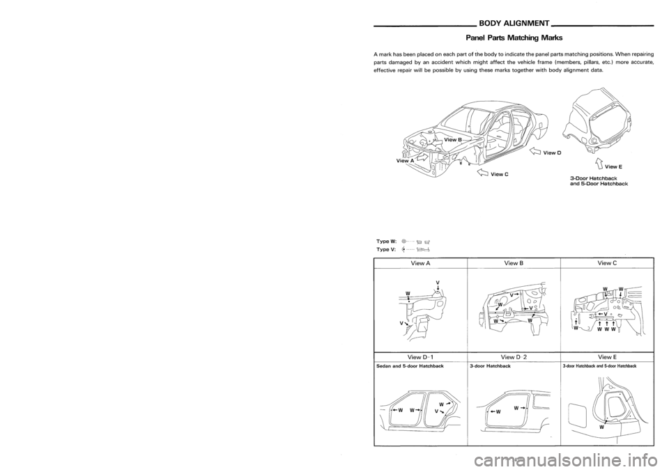
PanelPartsMatching Marks
~ViewE
3-Door Hatchback
and 5-Door Hatchback
A
mark hasbeen placed oneach partofthe body toindicate thepanel partsmatching positions.Whenrepairing
parts damaged byan accident whichmightaffectthevehicle frame(members, pillars,etc.)more accurate,
effective repairwillbepossible byusing these marks together wi~hbody alignment data.
Welding
current
Pressure
Unit:mrr
(C•
Thickness
(t)
Minimum pitch(
Q )
0.6 (0.024)
I
10 (0.39)
orover
0.8 (0.031) 12(0.47)
orover
1.0 (0.039) 18(0.71)
orover
1.2 (0.047) 20(0.79)
orover
1.6 (0.063) 27(1.06)
orover
~71) 31
11.221
orover
•
Follow established specifications forthe
appropriate pressurelevel,current leveland
weld time.
• Follow thespecifications forthe proper
welding pitch.
• After welding, weldingstrength mustbe
tested.
J
Type
W:
@----- ~
Et
Type V:~----- ~
View A ViewS
ViewC
View D-1 View
D-2
ViewE
Sedan and5-door Hatchback 3-door
Hatchback
3-door
Hatchback and5-door Hatchback
/w-..IE
+-W
II (-
'- r )
o
-31- -14-
Page 191 of 1701
__________ PRECAUTIONS ___________
BODYALIGNMENT _
Precautions ForHandling HighStregth Steel Engine
Compartment
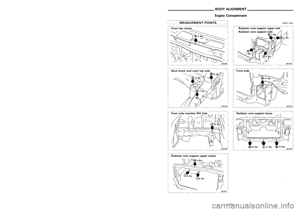
__ MEASURMENT POINTS__
Unit:mm
Front side
SBT088
Traction direction: ...
Not
recommended
• The repair ofreinforcements (suchasside
members) byheating isnot recommended
since itinvolves theriskoflowering strength.
When heating isunavoidable, donot heat
such parts attemperatures above550°C (1,
022°F)
Heating temperature shouldbeverified with
a thermometer. (Acrayon-type andother
thermometer areavailable.)
• When straightening bodypanels, usecaution
in pulling anyHSS panel. Because itis very
strong, thismay cause deformation inadja-
cent portions ofthe body. Inthis case,
increase thenumber ofmeasuring points,
and carefully pulltheHSS panel.
Special
consideration forHSS must begiven tothe following points:
1 .Additional pointstoconsider
• Incutting HSSpanel, avoidgascutting if
possible. Instead,useanairsaw orahand
cutter toavoid decreasing thestrength of
surrounding portionsduetothe influence of
heat. Incase gascutting isinevitable, a
minimum allowance of50 mm (1.97 in)
must begiven.
SBT090
Radiator
coresupport lower
•
(b)
11
dia.
SBT094
• Inwelding HSSpanel, usespot welding
whenever possibleinorder tominimize any
decrease instrength ofsurrounding portions
due tothe influence ofheat.
If spot welding isimpossible, useM.LG.
welding. Donotuseacetylene gaswelding
because itis inferior inwelding strength.
GOOD
-================
N.G.
Never useacetylene .gas
welding.
Radiator
coresupport uppercenter
SBT091
-29-
-16-