1995 NISSAN ALMERA N15 air filter
[x] Cancel search: air filterPage 53 of 1701
('l:,~~
o
\~A~~l
o
u~!~~:
Contact
0
9
&k .~
'"~~~~~)(?~~
SIR
accumulator piston ~./
SAT023DB
SAT129E
SAT024D DISASSEMBL
Y
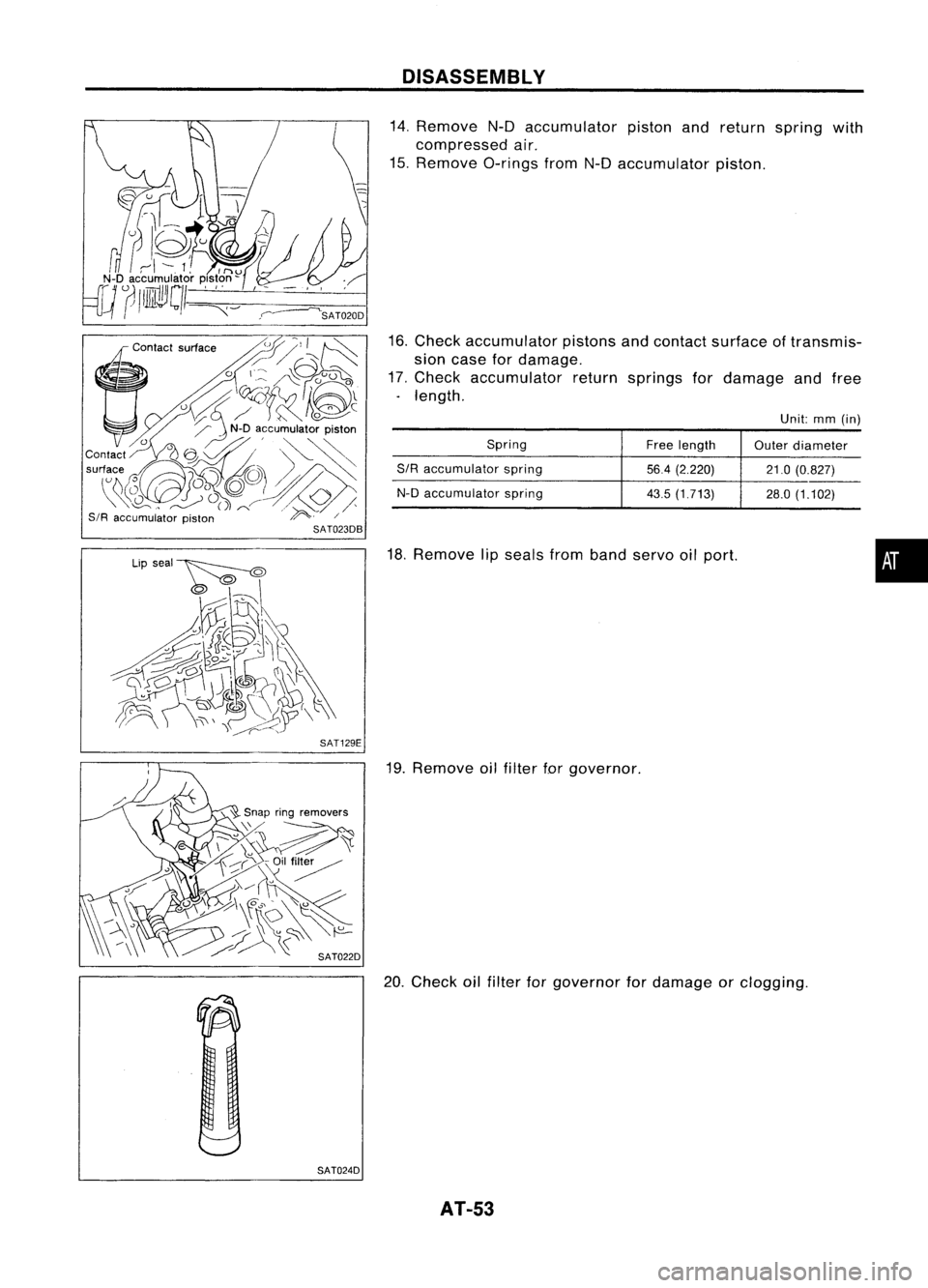
14. Remove N-Daccumulator pistonandreturn spring with
compressed air.
15. Remove O-ringsfromN-Daccumulator piston.
16. Check accumulator pistonsandcontact surface oftransmis-
sion case fordamage.
17. Check accumulator returnsprings fordamage andfree
. length.
Unit:mm(in)
Spring Freelength
Outerdiameter
SIR accumulator spring
56.4(2.220) 21.0(0.827)
N-D accumulator spring
43.5(1.713)
28.0(1.102)
18. Remove lipseals fromband servo oilport.
19. Remove oilfilter forgovernor.
20. Check oilfilter forgovernor fordamage orclogging.
AT-53
•
Page 392 of 1701

GROUNDDISTRIBUTION
GROUND CONNECTTO CONN.
NO. CELLCORD
E37/E51 AIRBAG DIAGNOSIS SENSORUNIT(Single
E108 RS-SRS
air bag system)
BRAKE FLUIDLEVEL SWITCH E2EL-WARN
CLEARANCE LAMPLH E50EL-TAILIL
CLEARANCE LAMPRH E33EL-TAILIL
COOLING FANMOTOR-1 (1-modetype) E45 EC-COOLIFHA-A/C
COOLING FANMOTOR-1 (2-modetype-GA
E66 EC-COOLIF
HA-A/C
engine forEurope)
COOLING FANMOTOR-1 (2-modetype-ex-
E46 EC-COOLIF
HA-A/C
eept GAengine forEurope)
COOLING FANMOTOR-2 (1-modetype)
E39 EC-COOLIFHA-A/C
-
COOLING FANMOTOR-2 (2-modetype-GA
E67 EC-COOLiF
HA-A/C
engine forEurope)
COOLING FANMOTOR-2 (2-modetype-ex-
E40 EC-COOLIFHA-A/C
eept GAengine forEurope)
COOLING FANRELAY-1 E12
EC-COOLIFHA-A/C
COOLING FANRELAY-2 E17
EC-COOLIFHA-A/C
COOLING FANRELAY-3 E18EC-COOLIF
HA-A/C
DAYTIME LIGHTUNIT E119EL-DTRL
FRONT FOGLAMP LH E52EL-F/FOG
FRONT FOGLAMP RH
E36EL-F/FOG
FRONT TURNSIGNAL LAMPLH E53EC-TURN
FRONT TURNSIGNAL LAMPRH E32EC-TURN
FRONT WIPERANDWASHER SWITCH E113
EL-WIPER
FUEL FILTER SWITCH
E5EL-WARN
HEADLAMP AIMINGMOTOR UNITLH E48
EL-AIM
HEADLAMP AIMINGMOTOR UNITRH E35 EL-AIM
HEADLAMP LH E49EL-H/LAMP
EL-DTRL
HEADLAMP RH E34EL-H/LAMP
EL-DTRL
HEADLAMP WIPERMOTOR LH E44
EL-HLC
HEADLAMP WIPERMOTOR RH E41EL-HLC
IACV-FICD SOLENOID VALVE(LHDmodels
.
E65 EC-A/CCUTHA-A/C
with CD20 engine)
INHIBITOR SWITCH E222EC-PNP/SWAT-A
IT EL-START
NEUTRAL POSITION SWITCH E220EC-PNP/SW
POWER STEERING OILPRESSURE SWITCH
E3 EC-PST/SW
(RHO models withgasoline engine)
REAR FOGLAMP RELAY E20EL-R/FOG
REAR WIPER ANDWASHER SWITCH E112EL-WIP/R
REAR WIPER RELAY E15EL-WIP/R
SIDE TURN SIGNAL LAMP(Driver side) E1 EL-TURN
WASHER FLUIDLEVEL SWITCH E30EL-WARN
EL-20
Page 510 of 1701
WARNINGLAMPSANDBUZZER
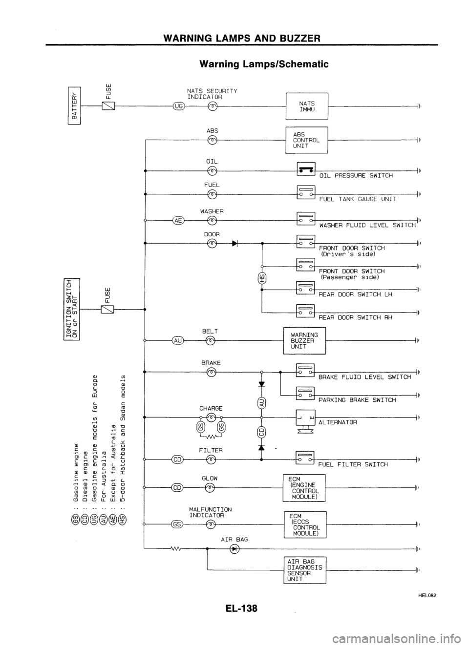
Warning Lamps/Schematic
>-
[[
W
f-
f-
CD
w
(f)
:J
l.L
UG
NATS
SECURITY
INDICATOR
NATSIMMU
ABS ABS
CONTROL
UNIT
OIL OILPRESSURE SWITCH
FUEL
FUELTANKGAUGE UNIT
WASHER
WASHERFLUIDLEVELSWITCH
DOOR
FRONTDOORSWITCH
(Driver's side)
FRONT DOORSWITCH
(Passenger side)
REAR ODOR SWITCH LH
ALTERNATOR PARKING
BRAKESWITCH
FUEL FILTER SWITCH
=
BRAKE
FLUIDLEVEL SWITCH
REAR
ODORSWITCH RH
=
WARNING
BUZZER
UNIT
=
ECM (ECCS
CONTROL
MODULE)
ECM
(ENGINE
CONTROL
MODULE)
I
U
f- W
H (f)
3:f-
:J
(f)[[
l.L
Zf-
O(f)
H
f-L
HO
Z
BELT
C!JZ
HO
BRAKE
Q)
(I)
D.
rl
0
Q)
L
D
::J
0
W
E
L
C
0
ro
""-
D
Q)
(I)
(f)
rl
Q)
ro
D
D
'M
C
0
rl
ro
E
ro
L
~
Q) Q)
.....
u
C C
(I)
ro
.M
Q)
.M
ro
::J
.0
OJ
C
OJ
.M
c
.M
C
rl
U
Q)
OJ
Q)
ro
L
+'
C
L
0
ro
Q) Q) Q)
.....
""-
I
C C
(I)
GLOW
.M
rl
.
M
::J
.....
L
rl
Q)
rl
0
0
(I)
0
Q)
0
(I)
Q)
(I)
L
u
D
ro
.M
ro
0
x
I
C!J
0
C!J
l.L
W
lD
MALFUNCTION
@@~@@@
INDICATOR
AIRBAG
AIRBAG
DIAGNOSIS
SENSOR
UNIT
HEL082
EL-138
Page 737 of 1701
ENGINEANDEMISSION CONTROL OVERALLSYSTEM
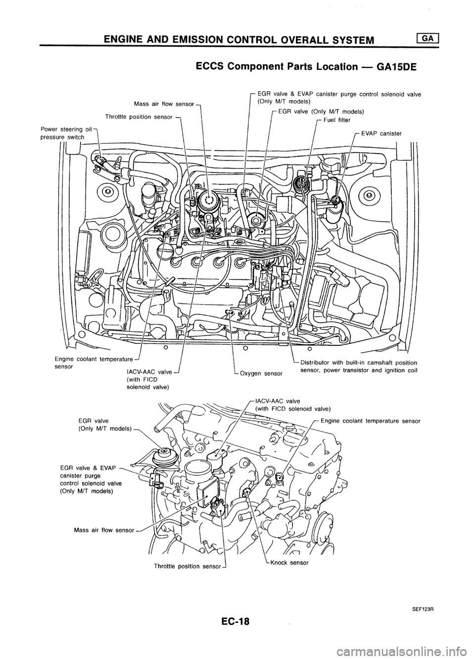
ECCS Component PartsLocation -GA15DE
Distributor withbuilt-in camshaft position
sensor, powertransistor andignition coil
EGR
valve
&
EVAP canister purgecontrol solenoid valve
(Only M/Tmodels)
f
EGR valve (Only M/Tmodels)
Fuel filter
EVAPcanister
Oxygen sensor
Mass
airflow sensor
IACV-AAC valve
(with FICD
solenoid valve)
Throttle
position sensor
Engine coolant temperature
sensor
Massairflow sensor
Throttleposition sensor
SEF123R
EC-18
Page 750 of 1701
POSITIVECRANKCASE VENTILATION
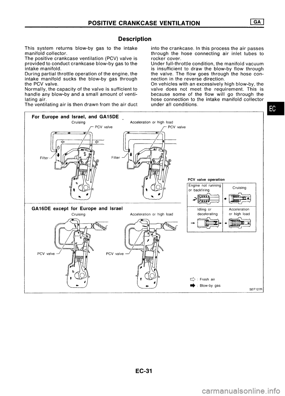
Description
intothecrankcase. Inthis process theairpasses
through thehose connecting airinlet tubes to
rocker cover.
Under full-throttle condition,themanifold vacuum
is insufficient todraw theblow-by flowthrough
the valve. Theflow goes through thehose con-
nection inthe reverse direction.
On vehicles withanexcessively highblow-by, the
valve doesnotmeet therequirement. Thisis
because someofthe flow willgothrough the
hose connection tothe intake manifold collector
under allconditions.
This
system returnsblow-by gastothe intake
manifold collector.
The positive crankcase ventilation (peV)valveis
provided toconduct crankcase blow-bygastothe
intake manifold.
During partialthrottle operation ofthe engine, the
intake manifold suckstheblow-by gasthrough
the
pev
valve.
Normally, thecapacity ofthe valve issufficient to
handle anyblow-by andasmall amount ofventi-
lating air.
The ventilating airisthen drawn fromtheairduct
•
SEF127R
Q:
Fresh air
• :Blow-by gas
PCV
valve
operation
Engine notrunning
Cruising
or backfiring
~~ .~
Idling or Acceleration
decelerating or
high load
-~ .~
..
Acceleration
orhigh load
Acceleration
orhigh load
pcv valve
Filter
For
Europe andIsrael, andGA15DE
Cruising
GA16DE exceptforEurope andIsrael
Cruising
EC-31
Page 792 of 1701
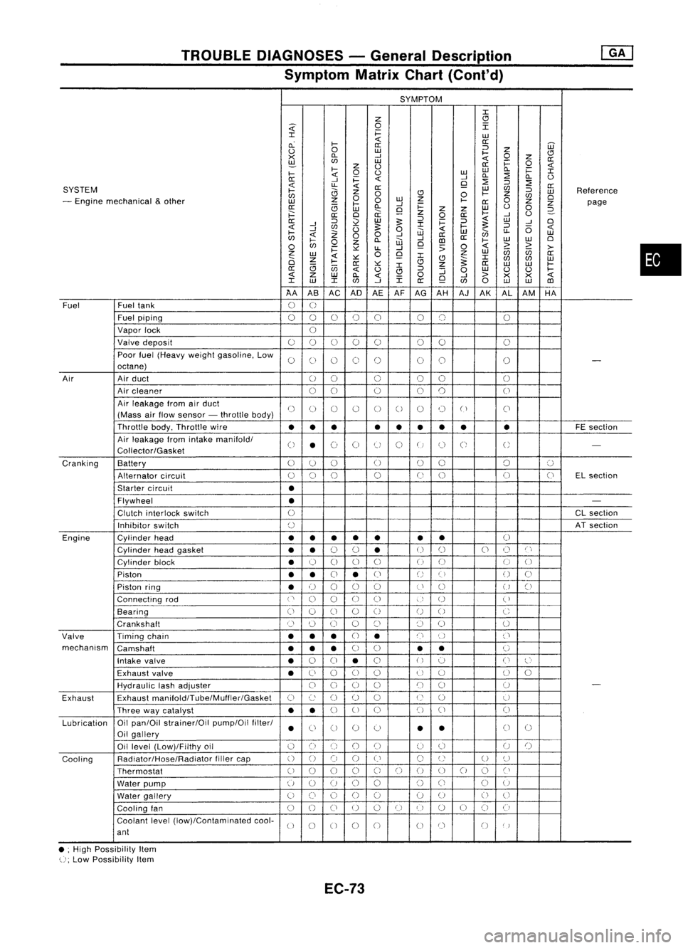
TROUBLEDIAGNOSES -General Description
Symptom MatrixChart(Cont'd)
SYMPTOM
J:
Z
CJ
~
0
I
J:
i=
LU
cL
I-
«
a:
a: ::J
UJ
0
0
LU
I-
Z
CJ
><
D..
-'
«
0
z
a:
~
LU
i=
0
z
0
a:
«
I-
0
0
LULU
D..
i=
J:
I-
«
-'
D..
:2
D..
0
0:
-'
i=
«
9
:2
::J
:2
SYSTEM
«
LL
«
0:
LU
C/J
a:
I-
0
Z
0
CJ
0
I-
Z
::J
LU
Reference
C/J
0
C/J
0
- Engine mechanical
&
other
z
0
LU
Z
I-
0
LU
I-
-'
0:
Z
Z
page
0:
(3
LU
D..
9
i=
z
Z
LU
0
0
2-
;:::
a:
0
a:
z
0
a:
I-
-'
0
0:
::J
~
LU
5:
::J
i=
::J
«
LU
-'
0
-'
J:
5:
«
-'
C/J
0
5:
0
«
I-
::J
(5
«
I-
Z
W
LU
en
LL
LU
C/J
«
00
-'
-'
a:
a:
0
I-
0
Z
D..
W
CD
I-
LU
LU
0
C/J
i=
~
LL
-'
9
:>
0
«
>
~
>-
z
0
Z
LU
(ij
C/J
a:
LU
«
~
9
J:
J:
0
Z
CJ
~
C/J
C/J
LU
I-
0:
~
CJ
Z
a:
LU LU
I-
(3
(jj
J:
a:
«
0
CJ
::J
:J
0
LU
0 0
I-
«
z
LU
D..
«
0
-'
>
><><
«
J:
LU
J:
C/J
-'
J:
a:
9
C/J
0
LU LU
CD
AA ASAC AD
AEAF
AG AH AJAK ALAM HA
Fuel Fueltank
0
U
Fuel piping
00 0
()
0 00 0
Vapor lock
U
Valve deposit
00 000 00
0
Poor fuel(Heavy weightgasoline, Low
0
C)
0 0
()
00
0
-
octane)
Air Airduct
00 0
00
0
Air cleaner
00
0
0
0
0
Air leakage fromairduct
()
(J
()
()
0
0
0 0
("
)
C'
(Mass airflow sensor -throttle body)
Throttle body,Throttle wire
••• •
••
•• •
FE
section
Air leakage fromintake manifold/
0
•
(~)
0
tJ
0
U
C;
U
-
Collector/Gasket
Cranking Battery
0
U
()
(J
00 0
':J
Alternator circuit
()
0
0
0
(J
0 0
(J
ELsection
Starter circuit
•
Flywheel
•
-
Clutch interlock switch
0
CL
section
Inhibitor switch
()
ATsection
Engine Cylinderhead
••
• •
• •
•
()
Cylinder headgasket
••
0
0
•
U
()
0
()
C'
Cylinder block
•
0
0 0
0
()
(J
0
0
Piston
••
0
•
(J
()
()
()
0
Piston ring
•
U
00
0
U
()
U
()
Connecting rod
('
0
0
00
)
U
(
)
Bearing
(i
0
()
0
()
U
0
C
Crankshaft
Cl
(~)
0 0
()
()
0
0
Valve Timingchain
•••
CJ
•
n
()
('
mechanism Camshaft
•••
0
0
•
•
0
Intake valve
•
0
0
•
0
()
':J
0
l~'
Exhaust valve
•
C)
0
()
()
U
u
()
0
HydraUlic lashadjuster
00
0
0
()
()
0
-
Exhaust Exhaust
manifoldlTube/Muffler/Gasket
C)
c:
()
()
0
U
()
U
Three waycatalyst
••
0
U
0 0
()
0
Lubrication Oil
pan/Oil strainer/Oil pump/Oilfilter/
•
Ci
0 0
0
•
•
()
0
Oil gallery
Oil level (Low)/Filthy oil
()
0
()
()()
(J
0
U
()
Cooling Radiator/Hose/Radiator
fillercap
()
0 0
()
()
C)
U
U
()
Thermostat
00
0
0
C)
0
()
00
0
Cl
Water pump
u
0
U
0
0
()
Ci
C)
U
Water gallery
U
()
0
()
0 0
U
0
U
Cooling fan
0
()
CJ
U
0
U
I)
U
()
CJ
(i
Coolant level(low)/Contaminated cool-
U
0
0 0
0
00
()
)
ant
• ;High Possibility Item
U;
Low Possibility Item
EC-73
•
Page 995 of 1701
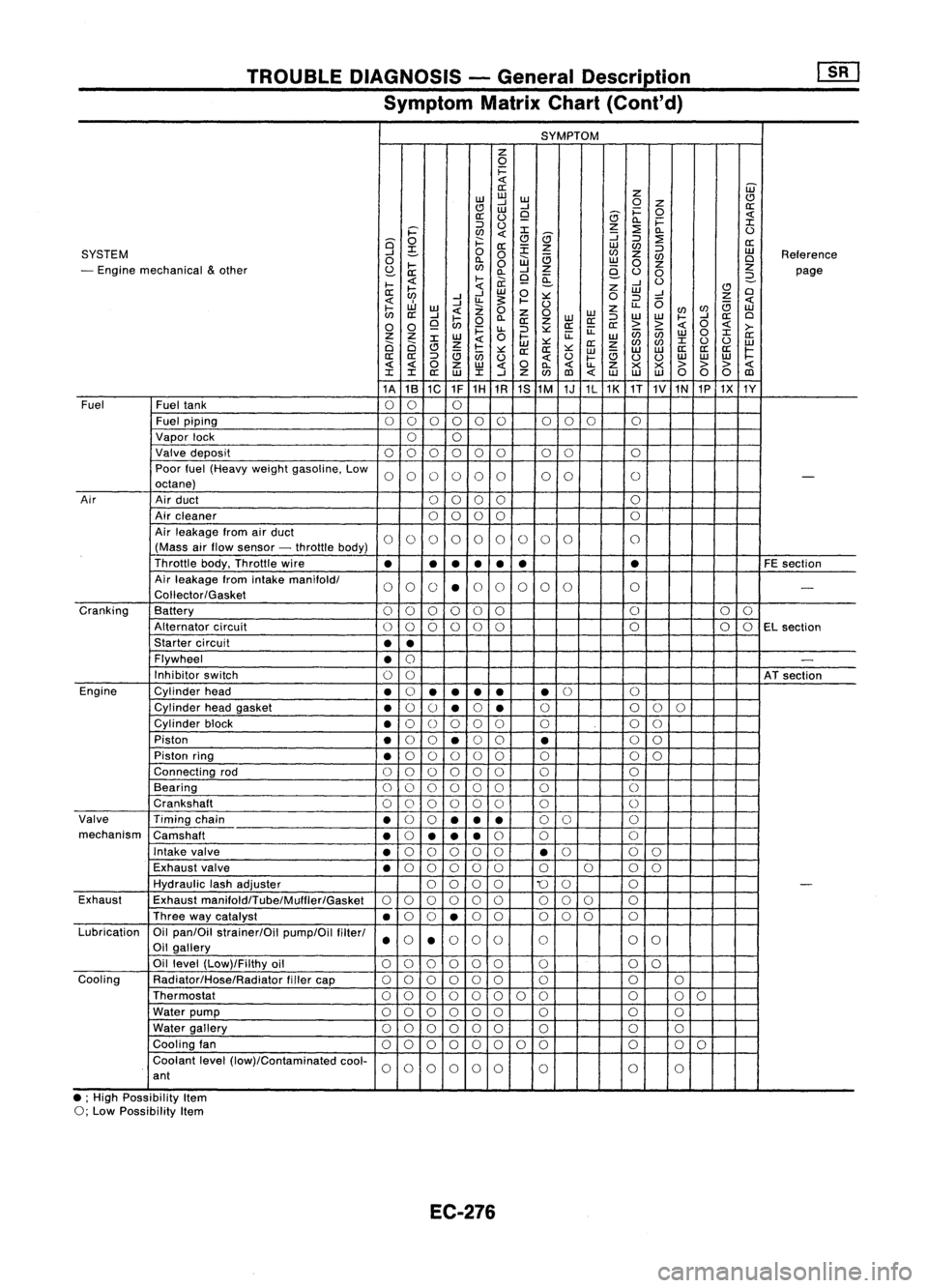
TROUBLEDIAGNOSIS -General Descrip_tio_n
1s_R_1
Symptom MatrixChart(Cont'd)
SYMPTOM
z
0
i=
«
W
a:
z
w
w
w
CJ
CJ
....J
....J
0
Z
a:
w
i=
0
a:
(.)
9
8
«
0.. i=
:I:
::J
(.)
z
:2
i='
en
«
:I:
8
:J
0..
(.)
Q
0
f:::.
CJ
:J
:2
a:
a:
:E
z
w
en
SYSTEM
....J
~
0
0
en
z
:J
w
Reference
0
0..
W
a
w
en
Cl
- Engine mechanical
&
other
I-
en
0
z
0
z
z
S:?-
a: 0..
....J
e-
(.)
0
page
I-
«
l-
ii.
9
~
....J
(.)
2-
a:
~
«
w
0
z
w
CJ
Cl
....J ....J
:.:::
0
:J
....J
Z
«
....J
u.
~
I-
(.)
u..
0
a
«
I-
w
«
Z
0
z
enen
w
en
a:
....J
I-
0..
Z
0
WW
:J
W
W
I-
....J
a:
Cl
0 0
9
en
0
a:
z
a:a:
a:
> >
«
0
«
>-
i=
u..
:J
:.:::
ii:
enen
0
:I:
Z Z
W
0
l-
ii:
w w
a:
Ci Ci
:I:
Z
«
w
:.:::
a:
z
en
en
:I:
(.)
(.)
w
CJ
a
I-
:.:::
a:a:
:.:::
w
a
w
w
a:
a:a:
~
a:
a:
:J
en
(.)
«
(.)
I-
(.)
(.)
w
w
w
« «
0
z
w
«
0
0..
«
u..
Z
x x
>>>
«
:I: :I:
a:
w
:I:
....J
Z
en
(l)
«
w w
w
00 0
(l)
1A 1B
1C 1F1H
1R 1S
1M 1J1L1K
1T
1V
1N
1P1X 1Y
Fuel Fueltank
00 0
Fuel piping
00 0000 000
0
Vapor lock
00
Valve deposit
000 000 00 0
Poor fuel(Heavy weightgasoline. Low
0000 00 00
0
-
octane)
Air Airduct
00 00 0
Air cleaner
0
0
00 0
Air leakage fromairduct
00 00 00 0
0 0
0
(Mass airflow sensor -throttle body)
Throttle body.Throttle wire
•
•
•
•
• •
•
FE
section
Air leakage fromintake
manifoldl
00 0
•
0
0 0
00 0
-
Coliector/Gasket
Cranking Battery
0
0
00 0
0 0
0
0
Alternator circuit
00
00
0
0 0
00
EL
section
Starter circuit
••
Flywheel
•
0
-
Inhibitor switch
00
ATsection
Engine Cylinderhead
•
0
•
•
••
•
0
0
Cylinder headgasket
•
0
()
•
0
•
0
0
00
Cylinder block
•
0
()
0 00 0 00
Piston
•
0
0
•
0
0
•
0
0
Piston ring
•
0
00 0
0 0 00
Connecting rod
00 00
00 0 0
Bearing
000 000 0
0
Crankshaft
00
0 0
0
0 0
0
Valve Timingchain
•
0
0
••
•
0
0 0
mechanism Camshaft
•
0
•• •
0
0 0
Intake valve
•
0
00 0
0
•
0
0
0
Exhaust valve
•
0
00 00 0000
Hydraulic lashadjuster
0000
'0
0 0
-
Exhaust Exhaust
manifoldlTube/Mulfler/Gasket
00
00 0
0
00
0 0
Three waycatalyst
•
0
0
•
0
0 000 0
Lubrication Oilpan/Oil strainer/Oil pump/Oilfilterl
000
0
0 0
0
Oil gallery
••
Oil level (Low)/Filthy oil
00 0000
0 0
0
Cooling Radiator/Hose/Radiator fillercap
00
0 00
0 0 00
Thermostat
00
00 0
0 00 0
00
Water pump
000 000 0 0
0
Water gallery
00 00 00
0 0
0
Cooling fan
00 0
00
0 0
0 0
0
0
Coolant level(low)/Contaminated cool-
00
0000
0 0
0
ant
• ;High Possibility Item
0; Low Possibility Item
EC-276
Page 1093 of 1701
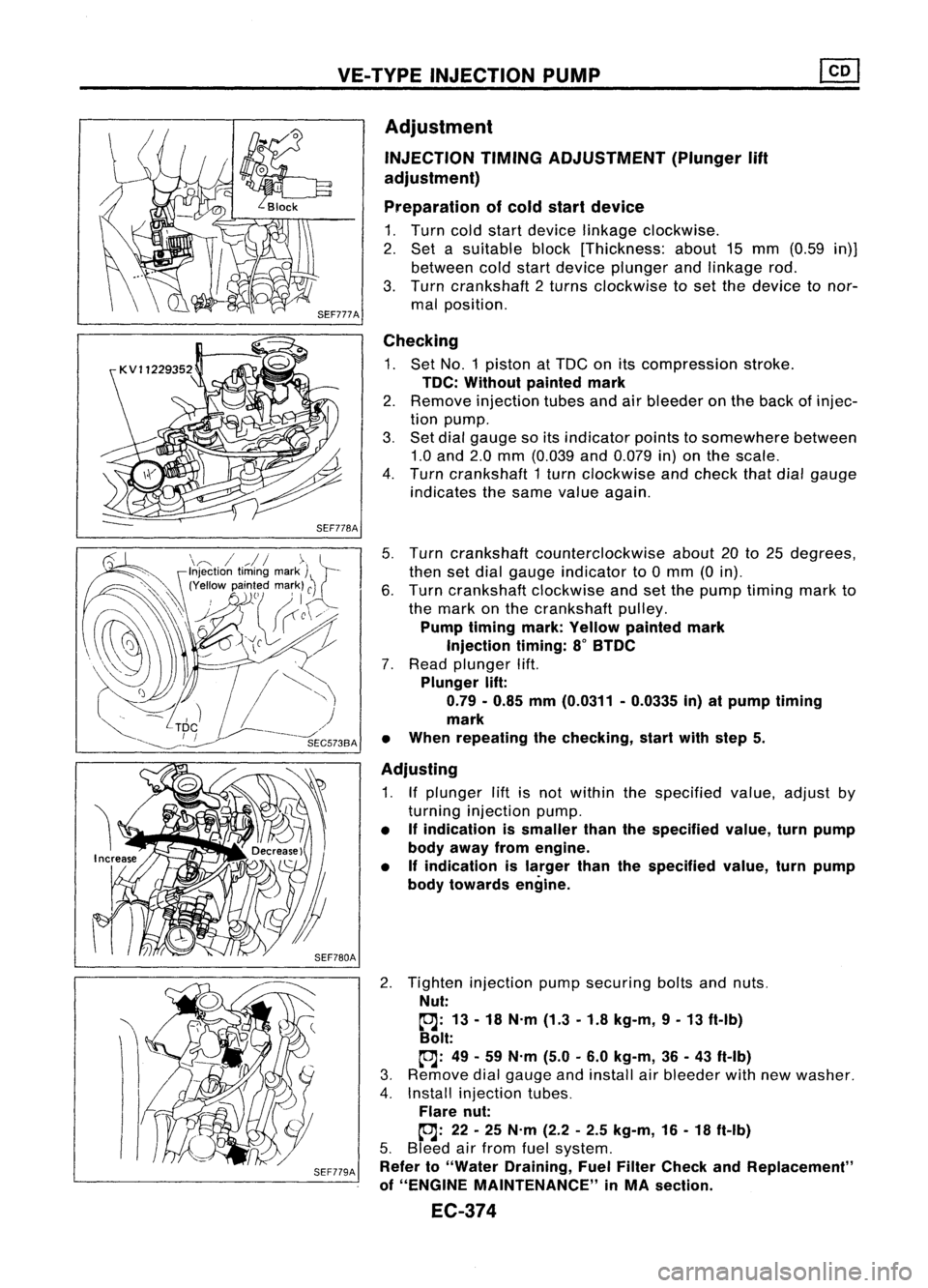
VE-TYPE INJECTION PUMP
SEF779A
Adjustment
INJECTION TIMINGADJUSTMENT (Plunger
lift
adjustment)
Preparation ofcold start device
1. Turn coldstart device linkage clockwise.
2. Set asuitable block[Thickness: about15mm (0.59 in)]
between coldstart device plunger andlinkage rod.
3. Turn crankshaft 2turns clockwise toset the device tonor-
mal position.
Checking
1. Set NO.1 piston atTDC onitscompression stroke.
TDC: Without paintedmark
2. Remove injection tubesandairbleeder onthe back ofinjec-
tion pump.
3. Set dial gauge soitsindicator pointstosomewhere between
1.0 and 2.0mm (0.039 and0.079 in)onthe scale.
4. Turn crankshaft 1turn clockwise andcheck thatdialgauge
indicates thesame value again.
5. Turn crankshaft counterclockwise about20to25 degrees,
then setdial gauge indicator to0mm (0in).
6. Turn crankshaft clockwiseandsetthe pump timing markto
the mark onthe crankshaft pulley.
Pump timing mark:Yellow painted mark
Injection timing:8
0
BTDC
7. Read plunger lift.
Plunger lift:
0.79 -0.85 mm(0.0311 -0.0335 in)atpump timing
mark
• When repeating thechecking, startwithstep 5.
Adjusting
1. Ifplunger liftisnot within thespecified value,adjust by
turning injection pump.
• Ifindication issmaller thanthespecified value,turnpump
body away fromengine.
• Ifindication islarger thanthespecified value,turnpump
body towards engine.
2. Tighten injection pumpsecuring boltsandnuts.
Nut:
~: 13-18 N.m (1.3-1.8 kg-m, 9-13 ft-Ib)
Bolt:
~: 49-59 N.m (5.0-6.0 kg-m, 36-43 ft-Ib)
3. Remove dialgauge andinstall airbleeder withnewwasher.
4. Install injection tubes.
Flare nut:
~: 22-25 N.m (2.2-2.5 kg-m, 16-18 ft-Ib)
5. Bleed airfrom fuelsystem.
Refer to"Water Draining, FuelFilter Check andReplacement"
of "ENGINE MAINTENANCE" inMA section.
EC-374