Page 447 of 1701

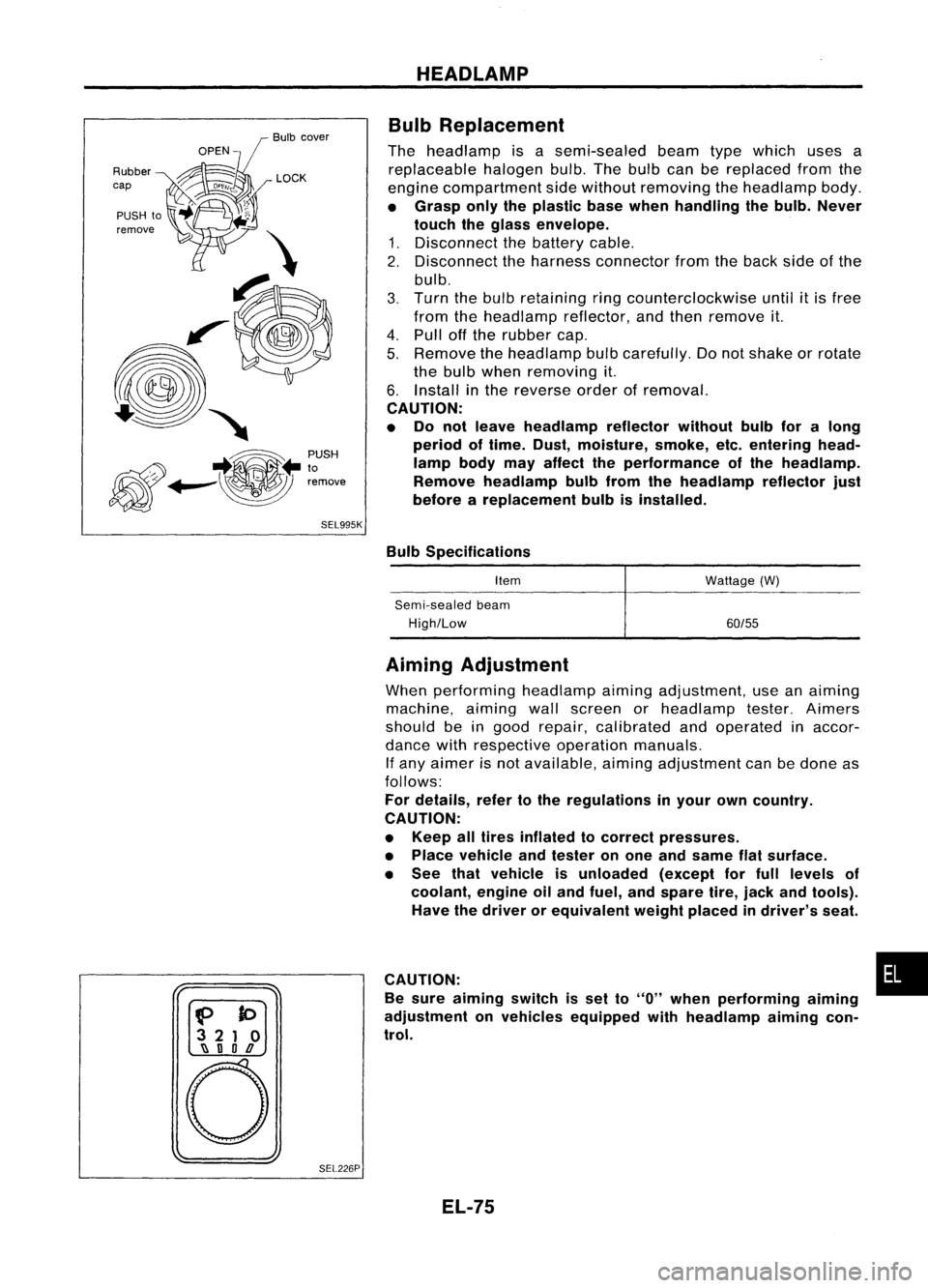
Bulbcover
SEL995K HEADLAMP
Bulb Replacement
The headlamp isasemi-sealed beamtypewhich usesa
replaceable halogenbulb.Thebulb canbereplaced fromthe
engine compartment sidewithout removing theheadlamp body.
• Grasp onlytheplastic basewhen handling thebulb. Never
touch theglass envelope.
1. Disconnect thebattery cable.
2. Disconnect theharness connector fromtheback sideofthe
bulb.
3. Turn thebulb retaining ringcounterclockwise until
it
is free
from theheadlamp reflector,andthen remove it.
4. Pull offthe rubber cap.
5. Remove theheadlamp bulbcarefully. Donot shake orrotate
the bulb when removing it.
6. Install inthe reverse orderofremoval.
CAUTION:
• Do not leave headlamp reflector withoutbulbforalong
period oftime. Dust,moisture, smoke,etc.entering head-
lamp bodymayaffect theperformance ofthe head lamp.
Remove headlamp bulbfrom thehead lamp reflector just
before areplacement bulbisinstalled.
Bulb Specifications
Item
Semi-sealed beam
High/Low Wattage
(W)
60/55
f>
to
3 21 0
~ nOD
o
SEL226PAiming
Adjustment
When performing headlamp aiming adjustment, useanaiming
machine, aimingwallscreen orheadlamp tester.Aimers
should beingood repair, calibrated andoperated inaccor-
dance withrespective operationmanuals.
If any aimer isnot available, aimingadjustment canbedone as
follows:
For details, refertothe regulations inyour owncountry.
CAUTION:
• Keep alltires inflated tocorrect pressures.
• Place vehicle andtester onone and same flatsurface.
• See thatvehicle isunloaded (exceptforfull levels of
coolant, engineoiland fuel, andspare tire,jack andtools).
Have thedriver orequivalent weightplaced indriver's seat.
CAUTION: •
Be sure aiming switchisset to
"0"
when performing aiming
adjustment onvehicles equipped withheadlamp aiming con-
trol.
EL-75
Page 473 of 1701

GEL001EXTERIOR
LAMP
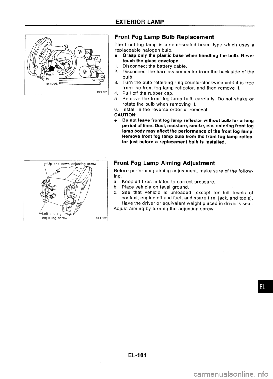
Front FogLamp BulbReplacement
The front foglamp isasemi-sealed beamtypewhich usesa
replaceable halogenbulb.
• Grasp onlytheplastic basewhen handling thebulb. Never
touch theglass envelope.
1. Disconnect thebattery cable.
2. Disconnect theharness connector fromtheback sideofthe
bulb.
3. Turn thebulb retaining ringcounterclockwise untilitis free
from thefront foglamp reflector, andthen remove it.
4. Pull offthe rubber cap.
5. Remove thefront foglamp bulbcarefully. Donot shake or
rotate thebulb when removing it.
6. Install inthe reverse orderofremoval.
CAUTION:
.' Donot leave frontfoglamp reflector withoutbulbforalong
period oftime. Dust, moisture, smoke,etc.entering frontfog
lamp bodymayaffect theperformance ofthe front foglamp.
Remove frontfoglamp bulbfrom thefront foglamp reflec-
tor just before areplacement bulbisinstalled.
Front FogLamp Aiming Adjustment
Before performing aimingadjustment, makesureofthe follow-
ing.
a. Keep alltires inflated tocorrect pressure.
b. Place vehicle onlevel ground.
c. See thatvehicle isunloaded (exceptforfull levels of
coolant, engineoiland fuel, andspare tire,jack, andtools).
Have thedriver orequivalent weightplaced indriver's seat.
Adjust aiming byturning theadjusting screw.
EL-101
•
Page 684 of 1701
PRECAUTIONSANDPREPARATION
Precautions
• When installing rubberparts,finaltightening mustbecar-
ried outunder unladen condition* withtires onground.
*: Fuel, radiator coolantandengine oilfull. Spare tire,
jack,
hand tools andmats indesignated positions.
• After installing removedsuspension parts,check wheel
alignment andadjust ifnecessary.
• Use flare nutwrench whenremoving orinstalling brake
tubes.
• Always torquebrakelineswhen installing.
Tool number
Tool name
SBR820B
Special Service Tools
Description
HT72520000
Ball joint remover Removing
tie-rodouterendandlower ball
joint
NT146
HT71780000
Spring compressor
ST35652000
Strut attachment
NT144
Removing
andinstalling coilspring
Fixing strutassembly
NT145
GG94310000
Flare nuttorque wrench
KV38106700
KV381 06800
Differential sideoilseal
protector
NT406
NT147
FA-2
Removing
andinstalling brakepiping
a:
10mm (0.39 in)
Installing driveshaft
LH: KV38106700
RH: KV38106800
Page 686 of 1701
FRONTSUSPENSION SYSTEM
SEC. 391-400-401
When installing rubberparts,finaltightening mustbecarried outunder unladen condition" withtires onground .
• Fuel, radiator coolantandengine oilfull. Spare tire,jack, hand tools andmats indesignated positions.
~~25.29
~ (2.5•3.0, 18•22)
\ \
...
5
~ 98•118 (10•12, 72•87)
Front
to.J:
N. m (kg-m, ft-Ib)
SFA715B
CD
Suspension member
@
Stabilizer bar
@
Drive shaft
@
Coilspring
@
Strut assembly
@
Knuckle
FA-4
(J)
Transverse link
@
Front struttower bar
Page 688 of 1701

ON-VEHICLESERVICE
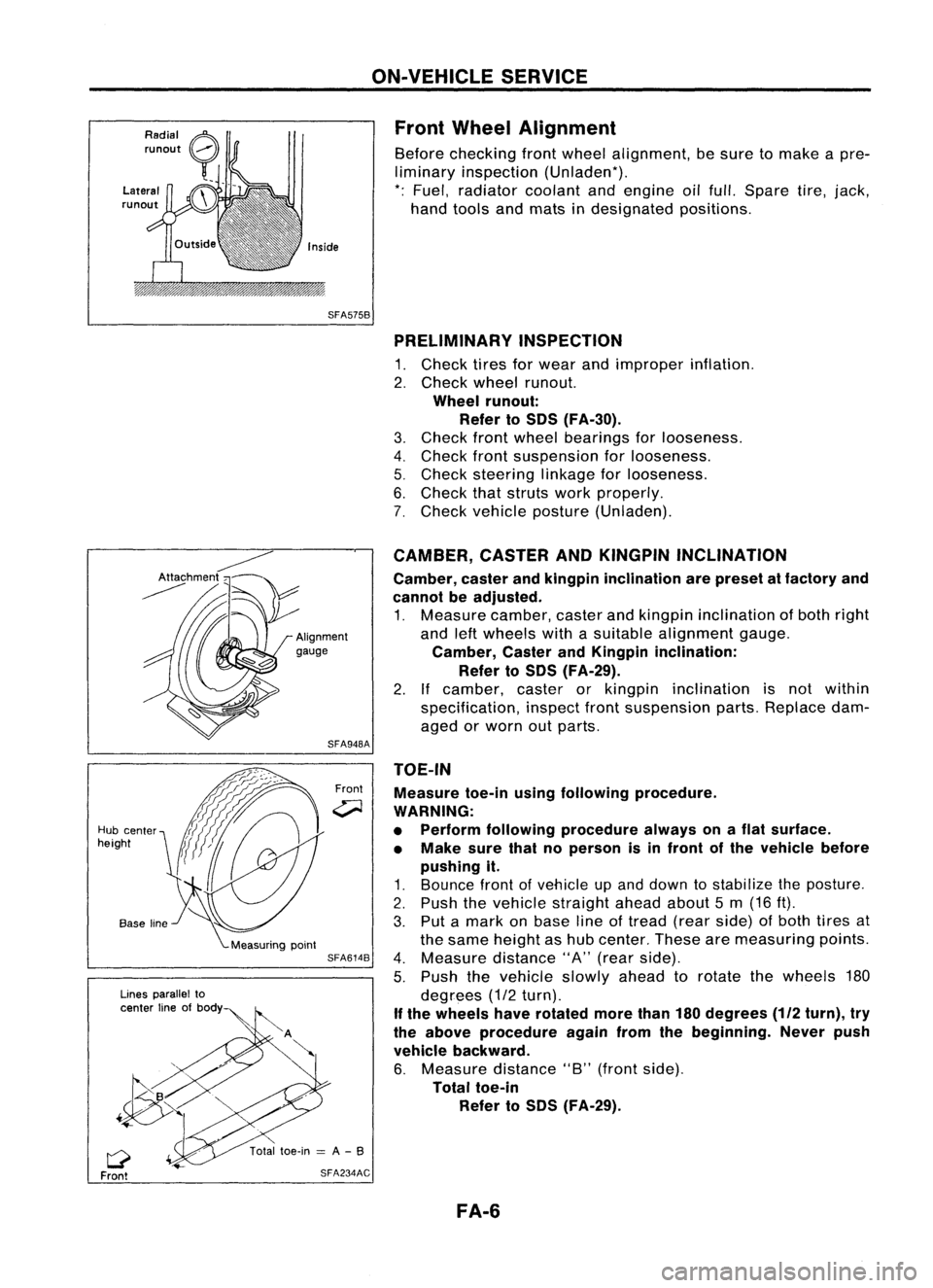
Front Wheel Alignment
Before checking frontwheel alignment, besure tomake apre-
liminary inspection (Unladen*).
*: Fuel, radiator coolantandengine oilfull. Spare tire,jack,
hand tools andmats indesignated positions.
SFA575B PRELIMINARY INSPECTION
1. Check tiresforwear andimproper inflation.
2. Check wheelrunout.
Wheel runout:
Refer toSOS (FA-30).
3. Check frontwheel bearings forlooseness.
4. Check frontsuspension forlooseness.
5. Check steering linkageforlooseness.
6. Check thatstruts workproperly.
7. Check vehicle posture (Unladen).
TOE-IN Measure toe-inusingfollowing procedure.
WARNING:
• Perform following procedure alwaysonaflat surface.
• Make surethatnoperson isin front ofthe vehicle before
pushing it.
1. Bounce frontofvehicle upand down tostabilize theposture.
2. Push thevehicle straight aheadabout5m (16 ft).
3. Put amark onbase lineoftread (rearside) ofboth tires at
the same height ashub center. Thesearemeasuring points.
4. Measure distance"A"(rear side).
5. Push thevehicle slowlyaheadtorotate thewheels 180
degrees (1/2turn).
If the wheels haverotated morethan180degrees
(112
turn), try
the above procedure againfromthebeginning. Neverpush
vehicle backward.
6. Measure distance"B"(front side).
Total toe-in
Refer toSOS (FA-29).
CAMBER,
CASTERANDKINGPIN INCLINATION
Camber, casterandkingpin inclination arepreset atfactory and
cannot beadjusted.
1. Measure camber,casterandkingpin inclination ofboth right
and leftwheels withasuitable alignment gauge.
Camber, CasterandKingpin inclination:
Refer toSOS (FA-29).
2. Ifcamber, casterorkingpin inclination isnot within
specification, inspectfrontsuspension parts.Replace dam-
aged orworn outparts.
Front
SFA948A
SFA614B
SFA234AC
Lines
parallel to
center lineofbody
Q
Front
Hub
center
height
FA-6
Page 706 of 1701
SEC.391.400.401
When installing rubberparts,finaltightening
must becarried outunder unladen condition'
with tires onground.
• Fuel, radiator coolanta'1dengine 011full.
Spare tire,Jack, hand toolsandmats In
designated positions.
@
~
L.~
(3.2-4.3, 23•31)
Front
CD
Spacer
@
Strut mounting insulator
@
Strut mounting insulator
bracket
@
Thrust bearing
@
Upper spring seat
@
Upper spring rubber seat
(J)
Bumper rubber
@
Coilspring
FRONT
SUSPENSION
@
Lower spring rubber seat
@)
Strut assembly
@
Suspension member
@
Stabilizer bar
@
Stabilizer clamp
@
Connecting rod
@
Transverse link
@
Compression rodclamp
@
Drive shaft
FA-24
~~
59.74
~~~.~ ::'.4:9- 54)
o
(2.5_3.0,
18 -22)
~
~~
~ ~
9=:
~~
-----J
/~18-24
1/ ~
(1.8.2.4,13.17)
~. @
&1
(@
~ J~!~5
(20-28, 145 •203)
~ 59•74 (6.0 -7.5, 43•54)
SFA624B
@
Knuckle
@
Cotter pin
@)
ABS sensor
@
Plain washer
@
Wheel bearing locknut
@
Insulator
@
Adjusting cap
@
Cotter pin
Page 711 of 1701

SERVICEDATAANDSPECIFICATIONS (50S)
General Specifications
Suspension type
Strut type
Stabilizer Independent
macpherson struts
Double-acting hydraulic
For 14-and 15-inch wheelmodels
Inspection andAdjustment
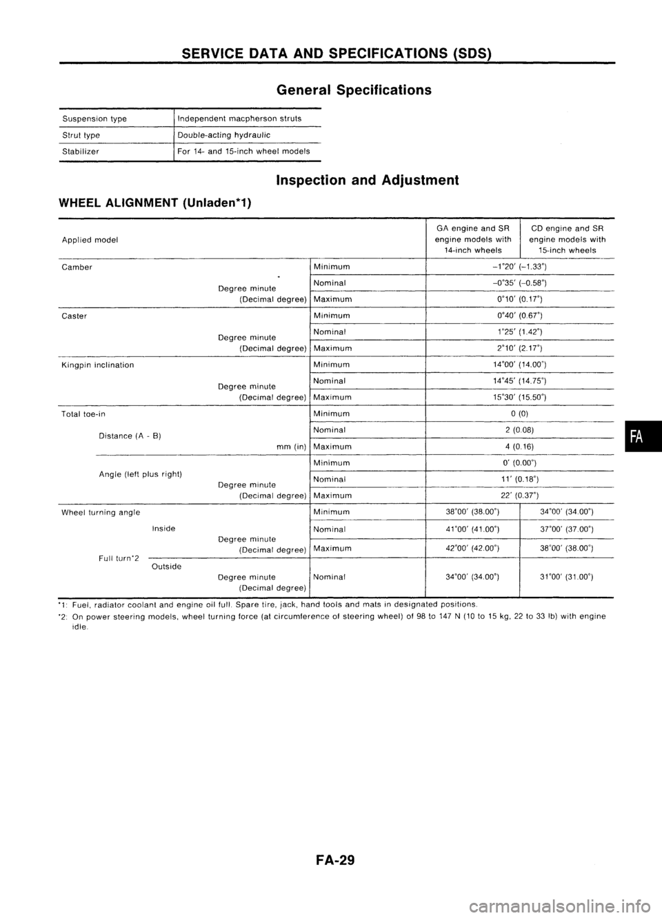
WHEEL ALIGNMENT (Unladen*1)
GAengine andSR CDengine andSR
Applied model engine
models with enginemodels with
14-inch wheels 15-inchwheels
Camber Minimum
-no'
(-1.33')
.
Degree minute Nominal
-0'35'
(-0.58')
(Decimal degree)Maximum 0'10'
(0.1
r)
Caster Minimum
0'40'(0.6r)
Degree minute Nominal
1
'25' (1.42')
(Decimal degree)Maximum 2'10'
(217")
Kingpin inclination Minimum14'00'
(14.00')
Degree minute Nominal
14'45'
(14.75')
(Decimal degree)Maximum 15'30'
(15.50')
Total toe-in Minimum0(0)
Distance (A-B) Nominal
2(008)
mm (in) Maximum 4(0.16)
Minimum 0'
(0.00')
Angle (leftplus right)
Nominal 11'
(0.18')
Degree minute
(Decimal degree)Maximum 22'
(0.37")
Wheel turning angle Minimum
38'00'
(38.00') 34'00'(34.00')
Inside Nominal4nO'
(41.00')
3rOO'(37.00')
Degree minute
(Decimal degree)Maximum
42'00'
(42.00')
38'00'(38.00')
Full (urn'2
Outside
Degreeminute Nominal 34'00'
(34.00') 31'00'(3100')
(Decimal degree)
'1' Fuel, radiator coolantandengine oilfull. Spare tire,jack, hand tools andmats indesignated positions.
'2: On power steering models,wheelturning force(atcircumference ofsteering wheel)of98 to147 N(10 to15 kg, 22to33 Ib)with engine
idle
FA-29
•
Page 1393 of 1701
IDENTIFICATIONINFORMATION
Dimensions SedanUnit:
mm(in) •
Hatchback
Overall length
Overall width
Overall height
Front tread
Rear tread
Wheelbase 4,320
(170.1)
1,690 (66.5)
1,395 (54.9)
1,480 (58.3)* 1
1,470 (57.9)*2
1,445 (56.9)*1
1,435 (56.5)*2
2,535 (99.8) 4,120
(162.2)
*1: For models with13-inch roadwheels
*2: For models with14-inch or15-inch roadwheels
Wheels andTires
Steel 13x5J 14x5-1/2JJ
-
Road Offset
mm(in) 35(1.38) 40(1.57)
wheel Aluminum 13x5J 14
x5-1/2JJ 15x6J
Offset mm(in)
35(1.38) 40
(1.57) 40(1.57)
175170R1382S 175/65R1482H
195/55R1584V
Conventional
185/65R1486H
Tire size 165SR13
Spare Conventional
Conventional Conventional
GI-39