1995 NISSAN ALMERA N15 Fuel pressure regulator
[x] Cancel search: Fuel pressure regulatorPage 720 of 1701
ENGINECONTROL SYSTEM
SECTION
EC
CONTENTS
•
PRECAUTIONS ANDPREPARATION
4
Special Service Tools 4
Supplemental RestraintSystem(SRS)"AIR
BAG" (DualAirBag System) 7
Supplemental RestraintSystem(SRS)"AIR
BAG" (Single AirBag System) 7
GA,SR
PRECAUTIONS ANDPREPARATION
8
Engine Fuel
&
Emission ControlSystem 8
Precautions forECCS Trouble Diagnosis of
Engine 9
Precautions 9
ENGINE ANDEMISSION CONTROLOVERALL
SYSTEM 11
Circuit Diagram -Except forAustralia 11
Circuit Diagram -For Australia 12
System Diagram -GA 14DE, GA16DE for
Europe andIsrael 13
System Diagram -GA15DE 14
System Diagram -GA 16DE except for
Europe, IsraelandAustralia 15
System Diagram -GA 16DE forAustralia 16
ECCS Component PartsLocation -GA 14DE,
GA 16DE forEurope andIsrael 17
ECCS Component PartsLocation -GA15DE 18
ECCS Component PartsLocation -GA 16DE
except forEurope, IsraelandAustralia 19
ECCS Component PartsLocation -GA 16DE
for Austral ia 20
ECCS Component PartsLocation 21
Vacuum HoseDrawing 22
c=
~
GA
ENGINE
ANDEMISSION BASICCONTROL
SYSTEM DESCRiPTION 23
System Chart.. 23
Multiport FuelInjection (MFI)System 24
Distributor Ignition(01)System 27
Air Conditioning CutControl 28
Fuel CutControl (atnoload &high engine
speed) 28
EVAPORATIVE EMISSIONSYSTEM
29
Inspection 29
POSITIVE CRANKCASE VENTILATION 31
Description 31
Inspection 32
BASIC SERVICE PROCEDURE 33
Fuel Pressure Release 33
Fuel Pressure Check 33
Fuel Pressure Regulator Check 33
Injector Removal andInstallation 34
Idle Speed/lgnition Timing/ldleMixtureRatio
Adjustment ,35
ON-BOARD DIAGNOSTIC SYSTEMDESCRIPTION .44
Malfunction IndicatorLamp(MIL) 44
CONSULT .48
TROUBLE DIAGNOSIS -General Description
58
Introduction 58
Work Flow 59
Description forWork Flow 60
Diagnostic Worksheet 61
Diagnostic TroubleCode(DTC) Chart 62
Fail-Safe Chart 64
Basic Inspection 65
Fast IdleCam (FIC) Inspection and
Adjustment -For Europe andIsrael 68
Fast IdleCam (FIC) Inspection and
Adjustment -Except forEurope andIsrael. 68
Symptom MatrixChart 71
Page 721 of 1701
CONTENTS(Cont'd.)
CONSULT Reference ValueinData Monitor
Mode 74
Major Sensor Reference GraphinData
Monitor Mode 76
ECM Terminals andReference Value 78
TROUBLE DIAGNOSIS FORPOWER SUPPLY 88
Main Power Supply andGround Circuit.. 88
TROUBLE DIAGNOSIS FORDTC11 94
Camshaft PositionSensor(CMPS) 94
TROUBLE DIAGNOSIS FORDTC
12 101
Mass AirFlow Sensor (MAFS) 101
TROUBLE DIAGNOSIS FORDTC
13 108
Engine Coolant Temperature Sensor(ECTS) 108
TROUBLE DIAGNOSIS FORDTC
21 113
Ignition Signal 113
TROUBLE DIAGNOSIS FORDTC
34 119
Knock Sensor (KS) 119
TROUBLE DIAGNOSIS FORDTC
41 124
Intake AirTemperature Sensor(IATS) 124
TROUBLE DIAGNOSIS FORNON-DETECTABLE
ITEMS , '"
.128
Throttle Position Sensor 128
Vehicle SpeedSensor (VSS) 133
Start Signal 138
Injector 141
Fuel Pump 145
Idle AirControl Valve(IACV) -Auxiliary Air
Control (AAC)Valve 150
Cooling FanControl 156
Power Steering OilPressure Switch 169
Park/Neutral PositionSwitch 173
EVAP Canister PurgeControl Solenoid Valve179
EGR Valve andEVAP Canister PurgeControl
Solenoid Valve 183
Heated Oxygen Sensor(H02S) 189
Oxygen Sensor(02S) 194
Valve Timing Control (VTC) 198
IACV-FICD SolenoidValve 204
Electrical LoadSignal 211
Torque Converter ClutchSolenoid Valve 219
MIL
&
Data LinkConnectors 223
SR
ENGINE ANDEMISSION CONTROL OVERALL
SYSTE M
226
Circuit Diagram 226
System Diagram 227
ECCS Component PartsLocation 228
Vacuum HoseDrawing 231
System Chart... 232
ENGINE
ANDEMISSION BASICCONTROL
SYSTEM DESCRiPTION
233
Multipart FuelInjection (MFI)System 233
Distributor Ignition
(01)
System 235
Air Conditioning CutControl 236
Fuel CutControl (atnoload
&
high engine
speed) 237
EVAPORATIVE EMISSIONSYSTEM
238
Description 238
Inspection 238
POSITIVE CRANKCASE VENTILATION
240
Description 240
Inspection 240
BASIC SERVICE
PROCEDURE 241
Fuel Pressure Release 241
Fuel Pressure Check 241
Fuel Pressure Regulator Check 242
Injector Removal andInstallation 242
Idle Speed/Ignition Timing/IdleMixtureRatio
Adjustment 243
ON-BOARD DIAGNOSTIC SYSTEMDESCRIPTION ..250
Malfunction IndicatorLamp(MIL) 250
CONSULT 254
TROUBLE DIAGNOSIS -General Description
264
Introduction 264
Work Flow 265
Description forWork Flow 266
Diagnostic Worksheet 267
Diagnostic TroubleCode(DTC) Chart 268
Fail-Safe Chart 270
Basic Inspection 271
Symptom MatrixChart. 274
CONSULT Reference ValueinData Monitor
Mode 277
Major Sensor Reference GraphinData
Monitor Mode 279
ECM"Terminals andReference Value 281
TROUBLE DIAGNOSIS FORPOWER SUPPLY
286
Main Power Supply andGround Circuit.. 286
TROUBLE DIAGNOSIS FORDTC
11 289
Camshaft PositionSensor(CMPS) 289
TROUBLE DIAGNOSIS FORDTC
12 293
Mass AirFlow Sensor (MAFS) 293
TROUBLE DIAGNOSIS FORDTC
13 297
Engine Coolant Temperature Sensor(ECTS) 297
TROUBLE DIAGNOSIS FORDTC
21 301
Ignition Signal 301
TROUBLE DIAGNOSIS FORDTC
34 306
Knock Sensor (KS) 306
Page 722 of 1701
CONTENTS(Cont'd.)
TROUBLE DIAGNOSIS FORDTC
43 309
Throttle Position Sensor 309
TROUBLE DIAGNOSIS FORNON-DETECTABLE
ITEMS
314
Vehicle SpeedSensor (VSS) 314
Start Signal 317
Exhaust GasRecirculation (EGR)Valveand
EVAP Canister PurgeControl 319
Injector 324
Fuel Pump 327
Idle AirControl Valve(IACV)-Air Regulator 332
Idle AirControl Valve(IACV) -Auxiliary Air
Control (AAC)Valve :335
Idle AirControl Valve(IACV)-FICD Solenoid
Valve '"339
Cooling FanControl 343
Power Steering OilPressure Switch 354
Park/Neutral PositionSwitch 357
Heated Oxygen Sensor(H02S) 362
Torque
Converter
ClutchSolenoid Valve 367
Malfunction IndicatorLamp(MIL)
&
Data Link
Connector (DLC)forCONSULT 370
CD
INJECTION SYSTEM
371
VE.TYPE INJECTION PUMP
372
Removal 372
Installation 373
Adjustment 374
INJECTION NOZZLE
376
Removal andInstallation 376
Disassembly 376
Inspection 377
Cleaning 377
Assembly 378
Test andAdjustment 379
FUEL
SYSTEM CHECK
381
Priming PumpCheck 381
Fuel CutSolenoid Valve 381
CRANKCASE VENTILATION SYSTEM
382
Ventilation Hose 382
ENGINE ANDEMISSION CONTROLOVERALL
SYSTEM
383
Component PartsLocation 383
System Diagram 384
Circuit Diagram ,385
System Chart. 386
TROUBLE DIAGNOSES
387
ECM Terminals andReference Values 387
Quick-glow System 390
Partial LoadAdvance (PLA)Control 399
Cooling FanControl 404
Air Conditioner CutControl 413
Fuel CutControl 416
GA
SERVICE DATAANDSPECIFICATIONS
(505).417
General Specifications 417
Inspection andAdjustment.. 417
SR
SERVICE DATAANDSPECIFICATIONS
(505).418
General Specifications 418
Inspection andAdjustment.. .418
CD
SERVICE DATAANDSPECIFICATIONS
(505).419
VE-type Injection Pump 419
Injection Nozzle 419
•
When youread wiring diagrams:
• Read GIsection, "HOWTOREAD WIRING DIAGRAMS" .
• See Elsection, "POWER SUPPLYROUTING" forpower distribution circuit.
When youperform troublediagnoses, readGIsection, "HOWTOFOllOW FLOWCHART INTROU-
BLE DIAGNOSES" and"HOW TOPERFORM EFFICIENT DIAGNOSIS FORANELECTRICAL INCIDENT".
Page 752 of 1701
BASICSERVICE PROCEDURE
• FUEL PRESRELEASE. D
FUEL PUMP WILLSTOP BY
TOUCHING STARTDURING
IDLE.
CRANK AFEW TIMES AFTER
ENGINE STALL
---S-T~-RT--
SEF823K
Fuel
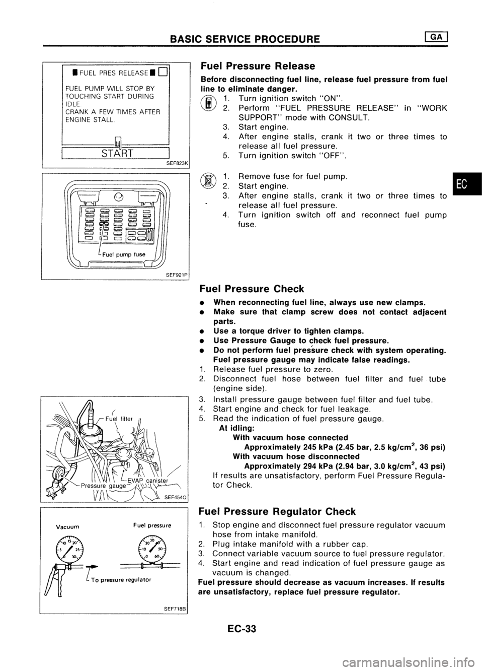
Pressure Release
Before disconnecting fuelline, release fuelpressure fromfuel
line toeliminate danger.
(ij\
1.Turn ignition switch"ON".
~ 2.Perform "FUELPRESSURE RELEASE"in"WORK
SUPPORT" modewithCONSULT.
3. Start engine.
4. After engine stalls,crankittwo orthree times to
release allfuel pressure.
5. Turn ignition switch"OFF".
SEF921P
00
~:
3.
4.
Remove
fuseforfuel pump. •
Start engine.
After engine stalls,crankittwo orthree times to
release allfuel pressure.
Turn ignition switchoffand reconnect fuelpump
fuse.
Vacuum Fuelpressure
..... L
To pressure regulator
Fuel
Pressure Check
• When reconnecting fuelline, always usenew clamps.
• Make surethatclamp screwdoesnotcontact adjacent
parts.
• Use atorque drivertotighten clamps.
• Use Pressure Gaugetocheck fuelpressure.
• Donot perform fuelpressure checkwithsystem operating.
Fuel pressure gaugemayindicate falsereadings.
1. Release fuelpressure tozero.
2. Disconnect fuelhose between fuelfilter andfuel tube
(engine side).
3. Install pressure gaugebetween fuelfilter andfuel tube.
4. Start engine andcheck forfuel leakage.
5. Read theindication offuel pressure gauge.
At idling:
With vacuum hoseconnected
Approximately 245kPa (2.45 bar,2.5kg/cm
2,
36psi)
With vacuum hosedisconnected
Approximately 294kPa (2.94 bar,3.0kg/cm
2,
43psi)
If results areunsatisfactory, performFuelPressure Regula-
tor Check.
Fuel Pressure Regulator Check
1. Stop engine anddisconnect fuelpressure regulator vacuum
hose fromintake manifold.
2. Plug intake manifold witharubber cap.
3. Connect variablevacuumsourcetofuel pressure regulator.
4. Start engine andread indication offuel pressure gaugeas
vacuum ischanged.
Fuel pressure shoulddecrease asvacuum increases. Ifresults
are unsatisfactory, replacefuelpressure regulator.
SEF7188
EC-33
Page 762 of 1701
![NISSAN ALMERA N15 1995 Service Manual BASICSERVICE PROCEDURE []KJ
Idle Speed/Ignition Timing/IdleMixtureRatio
Adjustment (Cont'd)
@
Connect oxygensensorharness connector tooxygen
sensor.
Check fuelpressure regulator.
(See page EC-33 NISSAN ALMERA N15 1995 Service Manual BASICSERVICE PROCEDURE []KJ
Idle Speed/Ignition Timing/IdleMixtureRatio
Adjustment (Cont'd)
@
Connect oxygensensorharness connector tooxygen
sensor.
Check fuelpressure regulator.
(See page EC-33](/manual-img/5/57349/w960_57349-761.png)
BASICSERVICE PROCEDURE []KJ
Idle Speed/Ignition Timing/IdleMixtureRatio
Adjustment (Cont'd)
@
Connect oxygensensorharness connector tooxygen
sensor.
Check fuelpressure regulator.
(See page EC-33.)
.
Check massairflow sensor anditscircuit.
(See page EC-107.)
Check injector anditscircuit.
(See page EC-141.)
Clean orreplace ifnecessary.
Check engine coolant temperature sensoranditscir-
cuit. (See page EC-112.)
Check ECMfunction* bysubstituting anotherknown
good ECM.
*.ECM maybethe caus
but this israrely thece
of aproblem,
ase.
•
EC-43
Page 774 of 1701
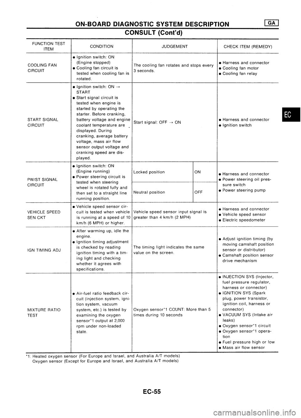
ON-BOARDDIAGNOSTIC SYSTEMDESCRIPTION
CONSULT (Conl'd)
FUNCTION TEST
CONDITION JUDGEMENT
ITEM CHECK
ITEM(REMEDY)
• Ignition switch:ON
COOLING FAN (Engine
stopped)
Thecooling fanrotates andstops every •
Harness andconnector
CIRCUIT •
Cooling fancircuit is
3seconds. •
Cooling fanmotor
tested whencooling fanis
•Cooling fanrelay
rotated .
• Ignition switch:ON-.
START
• Start signal circuit is
tested whenengine is
started byoperating the
starter. Beforecranking,
START SIGNAL batteryvoltage andengine
Startsignal: OFF-.ON •
Harness andconnector
CIRCUIT coolanttemperature are •
Ignition switch
displayed. During
cranking, averagebattery
voltage, massairflow
sensor outputvoltage and
cranking speedaredis-
played .
• Ignition switch:ON
(Engine running)
Lockedposition ON
•Harness andconnector
PW/ST SIGNAL •
Power steering circuitis
•Power steering oilpres-
tested whensteering
CIRCUIT wheelisrotated fullyand sure
switch
then settoastraight lineNeutral
position OFF•
Power steering pump
running position.
• Vehicle speedsensor cir-
•Harness andconnector
VEHICLE SPEED cuit
istested whenvehicle Vehicle
speedsensor inputsignal is
•Vehicle speedsensor
SEN CKT is
running ataspeed of10 greater
than4km/h (2MPH)
•Electric speedometer
km/h (6MPH) orhigher .
• After warming up,idle the
engine. •Adjust ignition timing(by
• Ignition timingadjustment
movingcamshaft position
IGN TIMING ADJ is
checked byreading The
timing lightindicates thesame
sensorordistributor)
ignition timingwithatim- value
onthe screen.
•Camshaft positionsensor
ing light andchecking
drivemechanism
whether itagrees with
specifications.
•INJECTION SYS(Injector,
fuel pressure regulator,
harness orconnector)
• Air-fuel ratiofeedback cir- •
IGNITION SYS(Spark
cuit (injection system,igni- plug,
power transistor,
tion system, vacuum ignition
coil,harness or
MIXTURE RATIO system,
etc.)istested byOxygen
sensor'1 COUNT:Morethan5 connector)
TEST examining
theoxygen times
during 10seconds •
VACUUM SYS(Intake air
sensor'1 outputat2,000 leaks)
rpm under non-loaded •
Oxygen sensor'1 circuit
state. •
Oxygen sensor'1 opera-
tion
• Fuel pressure highorlow
• Mass airflow sensor
'1: Heated oxygen sensor(ForEurope andIsrael, andAustralia AITmodels)
Oxygen sensor(Except forEurope andIsrael, andAustralia
A/T
models)
EC-55
•
Page 790 of 1701
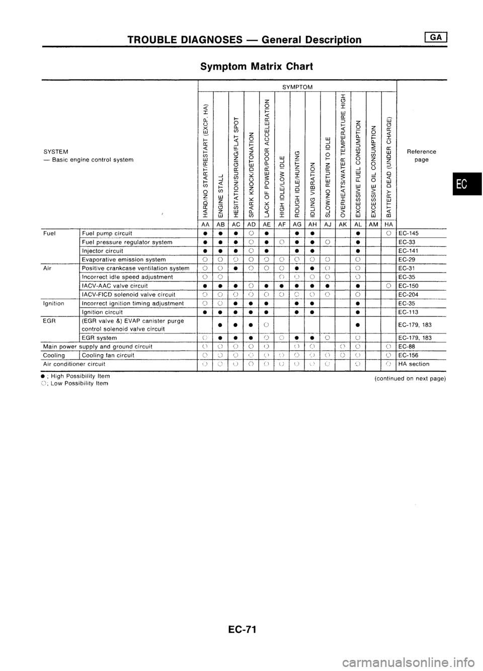
TROUBLEDIAGNOSES -General Description
Symptom MatrixChart
SYMPTOM
:c
z
(!l
~
0
I
:c
i=
w
cL
~
<{
0::
0::
='
W
<.)
0
w
~
z
CJ
x
Cl.
-I
0
Z
0::
~
en
w
i=
0
z
<.)
0::
<{
~
0
<.)
w
w
Cl.
i=
:c
~
-I
Cl.
::?
Cl.
<.)
0::
-I
i=
<{
Q
::?
=' ::?
<{
u..
<{
0::
SYSTEM
0::
W
en
='
Reterence
~
0
CJ
0
~
z
w
en
0
w
z
0
en
0
- Basic engine control system
w
z
0
~
0::
Z
Z
page
0::
<3
~
Cl.
-I
i=
w
<.)
0
w
Q
z
z
2-
j:::
0::
0
ii
z
0
0::
~
-I
<.)
0::
='
;;:
w
:s:
='
i=
='
<{
W
-I
0
<{
-I
en
:s:
:c
~
:s:
='
6
<{
-I
Z
<.)
0
w
<{
w
en
u..
w
~
<{
00
-I
0::
en
~
Cl.
W
-I
III
0::
~
W
W
0
0
en
0
z
Q
:;
0
<{
> >
i=
~
LL
-I
>-
Z
W
0
Q
z
w
U5 U5
0::
2i
z
<{
~ :c
(!l
~:c
en en
w
<3
~
0::
~
:c
CJ
z
0::
W W
~
0::
U5
<{
<.)
CJ
='
:J
0
w
<.)
<.)
~
I
<{
Z
W
Cl.
<{
0
Q
-I
>
X
X
<{
:c
w
:c
en
-I
:c
0::
en
0
w
W
III
AA AB AC ADAEAFAG
AH AJ
AK AL
AM HA
Fuel Fuel
pump circuit
••
•
0
•
•
•
•
0
EC-145
Fuel pressure regulator system
•••
0
•
0
•
•
0
•
EC-33
Injector circuit
•• •
0
• •
• •
EC-141
Evaporative emissionsystem
00
[)
00
()
0
0 0 0
EC-29
Air Positivecrankcase ventilation system
00
•
0
0
0
••
U
()
EC-31
Incorrect idlespeed adjustment
0
0
()
(~)
C)
0 0
EC-35
IACV-AAC valvecircuit
•••
(,
••• •• •
0
EC-150
~)
IACV-FICD solenoidvalvecircuit
C)
()
()
()
0
C)
(~,
()
0
0
EC-204
Ignition Incorrectignitiontimingadjustment
0
0
•• •
•
• •
EC-35
Ignition circuit
••
•
•
• •
•
•
EC-113
EGR (EGRvalve
&)
EVAP canister purge
0
EC-179,183
control soienoid valvecircuit
••
• •
EGR system
U
••
•
r)
(,)
•
•
0
0
EC-179.
183
Main power supply andground circuit
()
() ()
0 0
()
Ci
()
0
(
~
EC-88
Cooling
I
Cooling tancircuit
()
:.'-1
U
()
(,)
',)
C)
t)
U
n
(J
0
EC-156
u
Air conditioner circuit
()
Co
u
()
CJ
UU
"
,
C:
~,
()
HAsection
•
• ;High Possibility Item
(), Low Possibility Item
EC-71
(continued
onnext page)
Page 951 of 1701
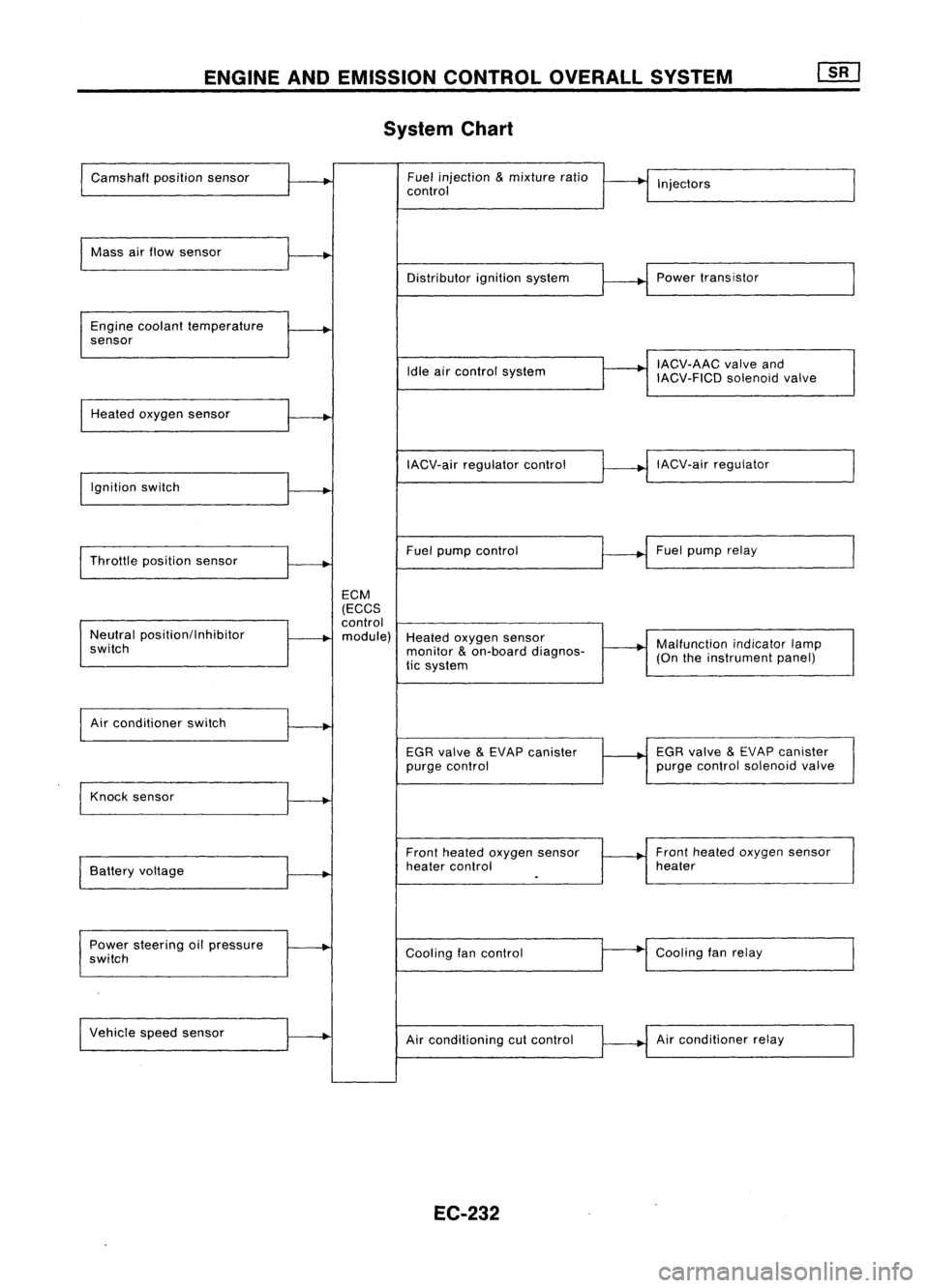
ENGINEANDEMISSION CONTROLOVERALLSYSTEM
System Chart
Camshaft positionsensor Fuel
injection
&
mixture ratio
•
I
I
control Injectors
Mass airflow sensor
I
Distributorignitionsystem
r
~1
Power transistor
Engine coolant temperature
.
sensor
I
IACV-AAC valveand
Idle aircontrol system
IACV-FICDsolenoidvalve
Heated oxygen sensor
I
IACV-airregulator control
~--..j
IACV-air regulator
I
Ignition switch
I
I
Throttle position sensor
~-+
Fuel
pump control Fuel
pump relay
ECM
(ECCS
control
Neutral position/Inhibitor
.
module) Heatedoxygen sensor
switch monitor
&
on-board diagnos-
~-+
Malfunction
indicatorlamp
tic system (On
theinstrument panel)
I
Air conditioner switch
t~
EGRvalve
&
EVAP canister
1---+
EGR
valve
&
EVAP canister
purge control purge
control solenoid valve
Knock sensor
.....
Frontheated oxygen sensor Front
heated oxygen sensor
Battery voltage
.
heater
control heater
I
.
Power steering oilpressure
~
Coolingfancontrol
--
Cooling
fanrelay
switch
Vehicle speedsensor
.....
Airconditioning cutcontrol Air
conditioner relay
EC-232