Page 14 of 1701

DESCRIPTION
Shift Mechanism
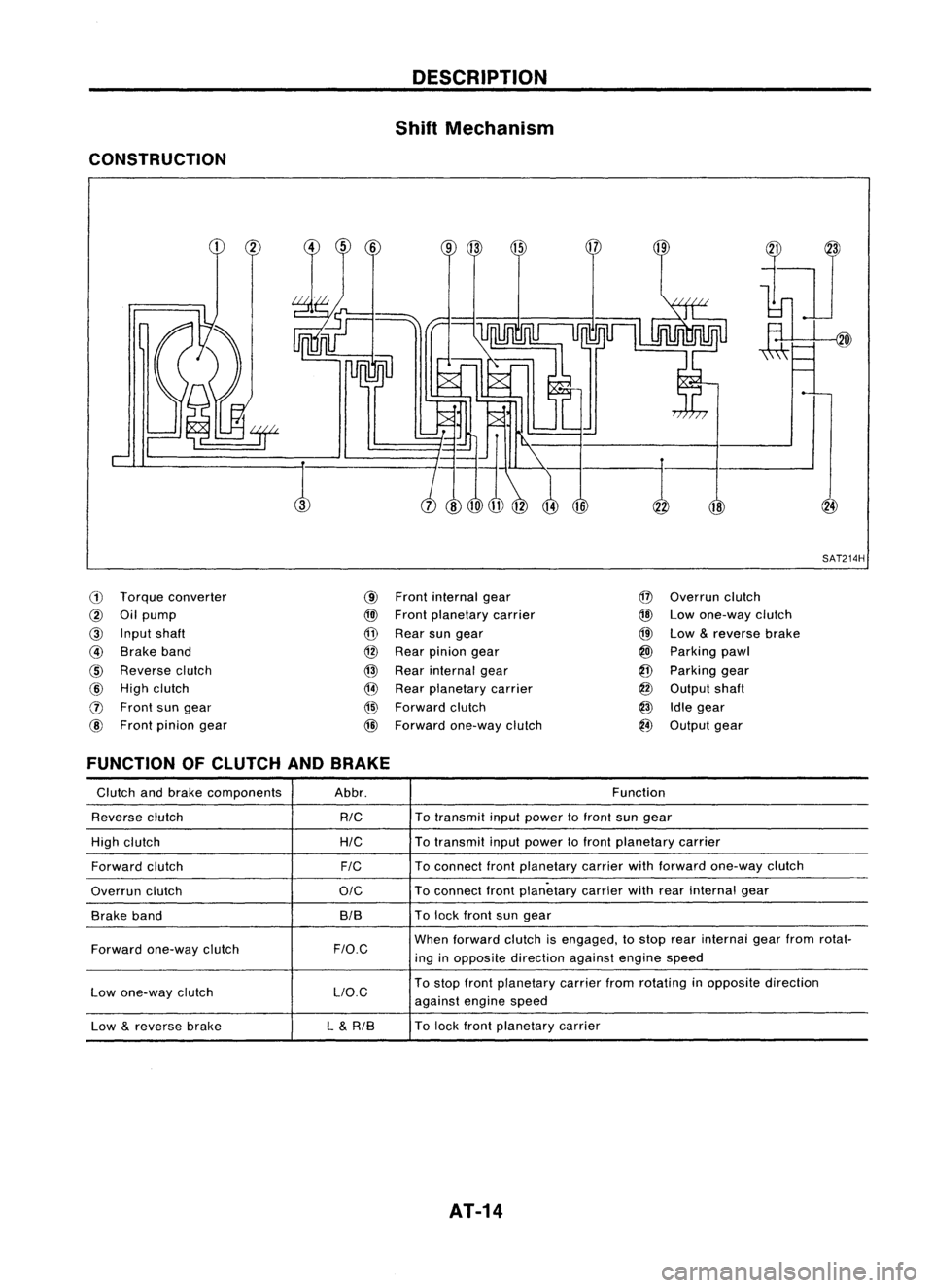
CONSTRUCTION
18
,:-1
SAT214H
ill
Torque converter
@
Oilpump
@
Input shaft
@
Brake band
@
Reverse clutch
@
High clutch
o
Front sungear
@
Front pinion gear
@
Front internal gear
@l
Front planetary carrier
@
Rear sungear
@
Rear pinion gear
@
Rear internal gear
@
Rear planetary carrier
@
Forward clutch
@
Forward one-way clutch
@
Overrun clutch
@
Lowone-way clutch
@
Low
&
reverse brake
@
Parking pawl
@
Parking gear
@
Output shaft
@
Idlegear
@
Output gear
FUNCTION OFCLUTCH ANDBRAKE
Glutch andbrake components Abbr. Function
Reverse clutch
RIG
To
transmit inputpower tofront sungear
High clutch
HIG
To
transmit inputpower tofront planetary carrier
Forward clutch
FIG
To
connect frontplanetary carrierwithforward one-way clutch
Overrun clutch
OIG
To
connect frontplanetary carrierwithrearinternal gear
Brake band BIBTo
lock front sungear
Forward one-way clutch
F/O.G
When
forward clutchisengaged, tostop rearinternai gearfrom rotat-
ing inopposite direction againstenginespeed
Low one-way clutch LlO.GTo
stop front planetary carrierfromrotating inopposite direction
against enginespeed
Low
&
reverse brake L
&
RIB To
lock front planetary carrier
AT-14
Page 15 of 1701

DESCRIPTION
Shift Mechanism (Cont'd)
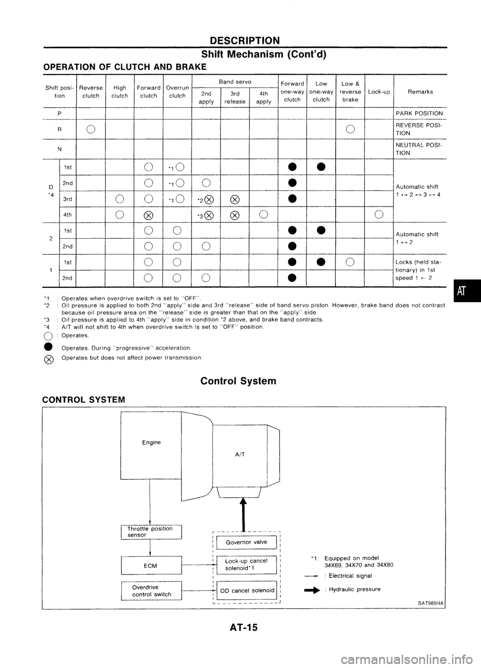
OPERATION OFCLUTCH ANDBRAKE
Bandservo
ForwardLow
Low
&
Shift posi- Reverse
HighForward
Overrun
Lock-upRemarks
tion clutch clutchclutchclutch 2nd
3rd4thone-way
one-way reverse
apply release
applyclutch
clutch brake
P PARK
POSITION
0 0REVERSE
POSI-
R TION
N NEUTRAL
POSI-
TION
1st 0'10
••
D 2nd
0'10
0
•
Automatic
shift
'4 00'10
'2@
@
•
1<-->2<-->3<-->4
3rd
4th 0@ '3@
@0
0
1st 00
••
Automatic
shift
2 1<-->2
2nd 00 0
•
1st 00
•
•
0
Locks
(heldsta-
1 tionary)
in1st
2nd 00 0
•
speed
1
<--
2
'1 Operates whenoverdrive switchissel to"OFF".
'2 Oilpressure isapplied toboth 2nd"apply" sideand3rd"release" sideofband servo piston. However, brakebanddoes notcontract
because oilpressure areaonthe "release" sideisgreater thanthatonthe "apply" side.
'3 Oilpressure isapplied to4th "apply" sideincondition '2above, andbrake bandcontracts.
'4 AIT
will notshift to4th when overdrive switchisset to"OFF" position.
o
Operates.
• Operates. During"progressive" acceleration.
@ Operates butdoes notaffect power transmission.
Control System
CONTROL SYSTEM
Engine
AIT
•
Lock-up cancel
solenoid'1
Overdrive
control switch
1:1
Governor valve
I
11
1
I
1
1
OD cancel solenoid :
; I
L
J
AT-15
'1:
Equipped onmodel
34X69, 34X70and34X80
: Electrical signal
.... :Hydraulic pressure
SAT985HA
Page 22 of 1701

TROUBLEDIAGNOSES
Road Testing (Cont'd)
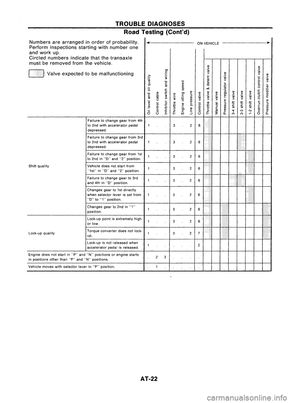
Numbers arearranged inorder ofprobability.
~
ONVEHICLE
..
Perform inspections startingwithnumber one
and work up.
Circled numbers indicatethatthetransaxle
must beremoved fromthevehicle.
(J)(J)
> >
01
0;
0;
. Valve expected tobe malfunctioning
c:
>
(J)
~ .;::
>>
(J)
.~
c
0;
>
0;
(J)
>
e
0;
"0 "0
Q)
C
>
::J
c:(J)
.8
rr
III
(J)
"0
0
~
0.
oil
III
<.>
'0
J::.
rtl
:;
J::.
ii
(J)
£
~(J)
(J)
(J) (J)
(J)(J)
£
"0
.~
~
01
>>
>
01
>>>
0
c: :0 c:
::J
0;0;
~
0;
0;0;
::J
E
III III
rtl
.~
rtl
0;
(3
<.>
~
rtl
>>
> >
>>
a; ~
(J) ~ (J)~
;:
'E
;t:
c:
~
>
e
.8
E (J)
0.
e
E
0;
::J
J::. J::.
:c
2
::J
~
:0
.!::
::J
rtl
rtl
C
e
(J)
c
0
c:
rtlrtl
rtlrtl
li;
rtl
J::.
01
c:
.c
III
(J)
"'f
C')
C)'
>
(J)
6
0
J::.
c:
0
a: a:
u
EO
~
UJ
::i
u
~
::E
C')
N
0
Failure tochange gearfrom 4th
to 2nd with accelerator pedal
32
6
depressed.
Failure tochange gearfrom3rd
to 2nd with accelerator pedal
32
6
depressed.
Failure tochange gearfrom 1st
32
6
to 2nd in"0" and"2"position.
Shift quality Vehicledoesnotstart from
32
6
"1st" in"0" and"2"position.
Failure tochange gearto3rd
32
6
and 4thin"0" position.
Changes gearto1st directly
when selector leverisset from
32
6
"D"
to"1" position.
Changes gearto2nd in"1"
3
2
6
position.
Lock-up pointisextremely high
32
6
or low.
Lock-up quality Torque
converter doesnotlock-
32
7
up.
Lock-up isnot released when
2
accelerator pedalisreleased.
Engine doesnotstart in"P" and "N" positions orengine starts
2
3
in positions otherthan"P"and "N" positions.
Vehicle moveswithselector leverin"P" position.
AT-22
Page 24 of 1701
TROUBLEDIAGNOSES
Stall Tasting
STALL TESTPROCEDURE
1. Check
AIT
and engine fluidlevels. Ifnecessary, addfluid.
2. Drive vehicle forabout 10minutes untilengine oiland ATF
reach operating temperature.
ATF operating temperature:
50 -80
0
e (122-176°F)
SAT6478
3.Set parking brakeandblock wheels.
4. Install atachometer whereitcan beseen bydriver during
test.
SAT513G 5.
~ ~ID
•
~c;>
SAT7678
Start
engine, applyfootbrake, andplace selector leverin
"0"
position.
6. Accelerate towide-open throttlegradually whileapplying
foot brake.
7. Quickly notetheengine stallrevolution andimmediately
release throttle.
• During test,never holdthrottle wide-open formore than5
seconds. Stall revolution .standard:
Refer toSDS, AT-166.
SAT514G
8.Move selector leverto"N" position.
9. Cool offATF.
• Run engine atidle foratleast oneminute.
10. Repeat steps5through 9with selector leverin"2", "1"and
"R
n
positions.
SAT7718 AT-24
Page 26 of 1701
TROUBLEDIAGNOSES
Pressure Testing
• Location ofpressure testport.
• Always replace pressure plugsasthey areself-sealing
bolts.
Test portfor
line pressure governor
pressure
SAT565D
LINEPRESSURE TESTPROCEDURE
1. Check AfTand engine fluidlevels. Ifnecessary, addfluid.
2. Drive vehicle forabout 10minutes untilengine oiland ATF
reach operating temperature.
ATF operating temperature:
50 -80°C (122-176°F)
SAT647B
3.Install pressure gaugetoline pressure port.
4. Set parking brakeandblock wheels.
Continue todepress brakepedalfullywhile performing line
pressure testatstall speed.
SAT513G
5.Start engine andmeasure linepressure atidle and stall
speed. Line pressure:
Refer toSOS, AT-166.
JUDGEMENT OFLINE PRESSURE TEST
• Ifline pressure doesnotrise, firstcheck tomake surethat
throttle wireisconnected properly.
1) When linepressure whileidling
is
low atall positions ("D",
"2", "1", "R"and"P"), theproblem maybedue to:
SAT494G •
Wear oninterior ofoil pump
AT-26
Page 27 of 1701

'-)
(
~)o
Front
SAT498GTROUBLE
DIAGNOSES
Pressure Testing(Cont'd)
• Oilleakage ator around oilpump, control valvebody, trans-
mission caseorgovernor
• Sticking pressure regulator valve
• Sticking pressure modifiervalve
2) When linepressure whileidling islow ataparticular
position, checkthefollowing.
• Ifoil leaks ator around low
&
reverse brakecircuit, line
pressure becomes lowin"R" position. Butline pressure is
normal in"P", "D", "2"or"1" position.
3) When linepressure ishigh while idling, pressure regulator
valve mayhave stuck.
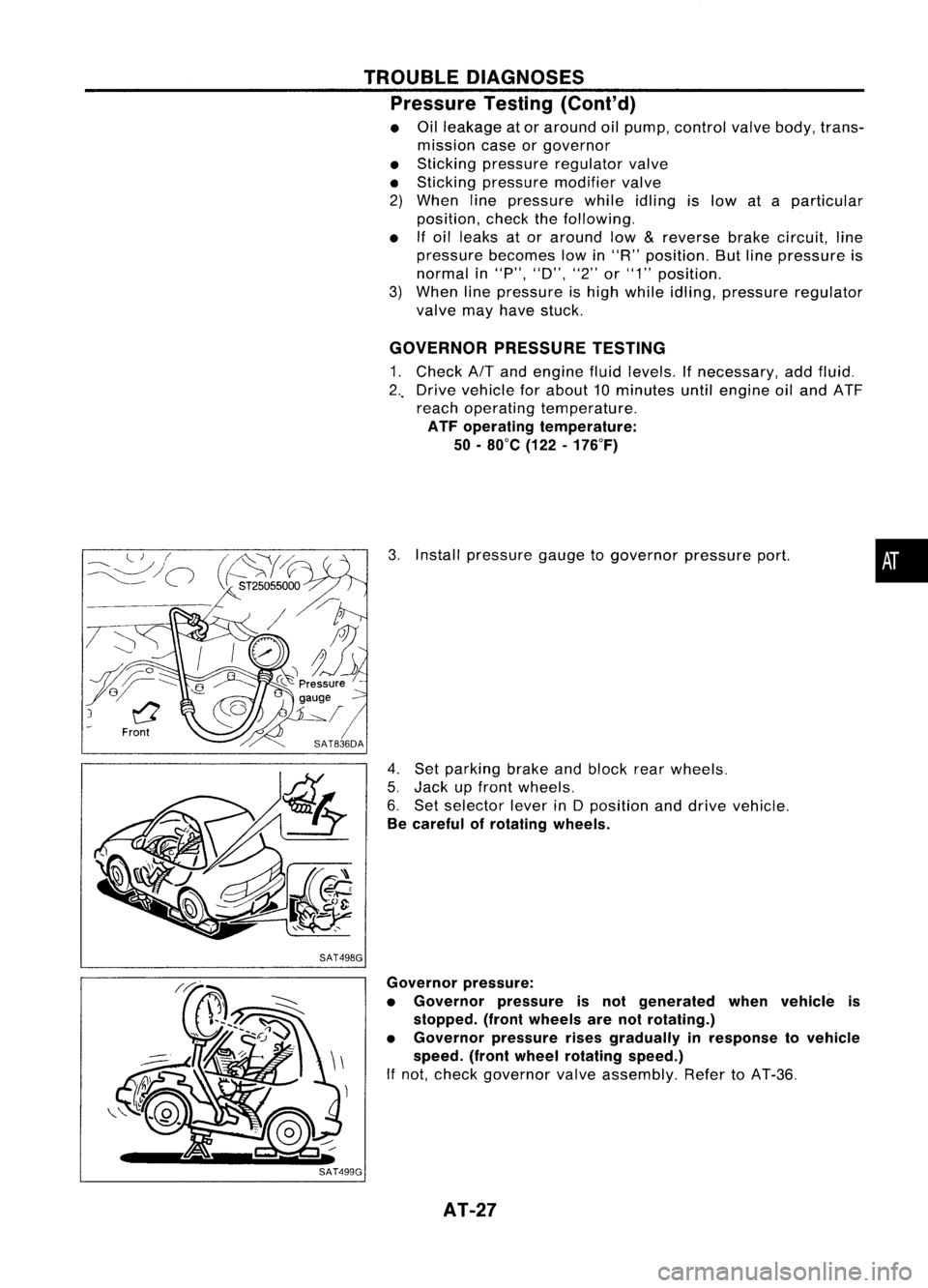
GOVERNOR PRESSURETESTING
1. Check
AIT
and engine fluidlevels. Ifnecessary, addfluid.
2 .. Drive vehicle forabout 10minutes untilengine oiland ATF
reach operating temperature.
ATF operating temperature:
50 -80°C (122-176°F)
3. Install pressure gaugetogovernor pressureport.
4. Set parking brakeandblock rearwheels.
5. Jack upfront wheels.
6. Set selector leverinDposition anddrive vehicle.
Be careful ofrotating wheels.
•
Governor pressure:
• Governor pressureisnot generated whenvehicle is
stopped. (frontwheels arenotrotating.)
• Governor pressurerisesgradually inresponse tovehicle
speed. (frontwheel rotating speed.)
If not, check governor valveassembly. RefertoAT-36.
AT-27
Page 39 of 1701
REMOVALANDINSTALLATION
Removal
• Remove batteryandbracket.
• Remove airduct.
• Disconnect
AIT
solenoid harnessconnector, inhibitorswitch
harness connector andspeedometer pinionharness con-
nector.
• Disconnect throttlewireatengine side.
• Drain ATF.
• Remove undercover andside cover.
• Disconnect controlcablefromtransaxle.
• Disconnect oilcooler hoses.
• Remove driveshafts -Refer toFA section ("Removal", •
"FRONT AXLE-Drive Shaft").
• Remove exhaustfronttube.
• Remove startermotorfromtransaxle.
• Remove frontandrear gussets andengine rearplate.
• Remove boltssecuring torqueconverter todrive plate.
Rotate crankshaft foraccess tosecuring bolts.
• Support enginebyplacing ajack under oilpan.
Do not place jackunder oilpan drain plug.
• Support transaxle withajack.
• Remove LHand rear mountings fromtransaxle.
• Remove boltsfixing
AIT
toengine.
• Lower transaxle whilesupporting
it
with ajack.
AT-39
Page 51 of 1701
SAT620EDISASSEMBL
Y
5. Set manual shaftto"P" position.
6. Remove inhibitorswitch.
Waste material
Oil
pan
SAT013D
7.
Remove oilpan andoilpan gasket.
• Donot reuse oilpan bolts.
8. Check foreign materials inoil pan tohelp determine cause•
of malfunction. Ifthe fluid isvery dark, smells burned, or
contains foreignparticles, thefrictional material(clutches,
band) mayneed replacement. Atacky filmthat willnotwipe
clean indicates varnishbuildup.Varnish cancause valves,
servo andclutches tostick andcaninhibit pumppressure.
• Iffrictional materialisdetected, replaceradiator afterrepair
of AlT. Refer toLC section ("Radiator", "ENGINECOOLING
SYSTEM").
SAT711D
9.
Remove controlvalveassembly according tothe following
procedures.
a. Remove controlvalveassembly mountingbolts@,
CID,
@
and @.
AT-51