1995 NISSAN ALMERA N15 heater
[x] Cancel search: heaterPage 375 of 1701
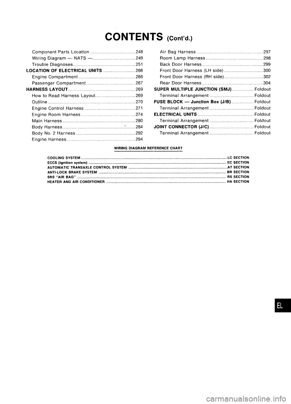
CONTENTS(Cont'd.)
Component PartsLocation 248
Wiring Diagram -NATS - 249
Trouble Diagnoses 251
LOCATION OFELECTRICAL UNITS
266
Engine Compartment 266
Passenger Compartment 267
HARNESS LAyOUT
269
How toRead Harness Layout... 269
Outline 270
Engine Control Harness 271
Engine RoomHarness 274
Main Harness '" 280
Body Harness :284
Body No.2 Harness 292
Engine Harness 294Air
Bag Harness 297
Room LampHarness 298
Back DoorHarness 299
Front DoorHarness (LHside) 300
Front DoorHarness (RHside) 302
Rear Door Harness 304
SUPER MULTIPLE JUNCTION
(SMJ) Foldout
Terminal Arrangement Foldout
FUSE BLOCK -Junction Box
(JIB)
Foldout
Terminal Arrangement Foldout
ELECTRICAL UNITS
Foldout
Terminal Arrangement Foldout
JOINT CONNECTOR
(J/C)
Foldout
Terminal Arrangement Foldout
WIRING DIAGRAM REFERENCE CHART
COOLING SYSTEM
LC
SECTION
ECCS (Ignition syslem) ECSECTION
AUTOMATIC TRANSAXLECONTROLSYSTEM ATSECTION
ANTI-LOCK BRAKESYSTEM BRSECTION
SRS "AIR BAG" RSSECTION
HEATER ANDAIRCONDITIONER HASECTION
•
Page 381 of 1701
![NISSAN ALMERA N15 1995 Service Manual POWERSUPPLY ROUTING
Schematic (Cont'd)
l5A~
F/FOG
20A
@J
LOAD,DEF
lOA
[8J
ABS,SToP/L
lOA
[ill
TURN
FICO, A!CCUT,
HEATER, A!e
HEATER, A!e
7.5A@Q]
lOA
@]
l5A
[ill
INT/L
GLOW, AIM,BUZZ NISSAN ALMERA N15 1995 Service Manual POWERSUPPLY ROUTING
Schematic (Cont'd)
l5A~
F/FOG
20A
@J
LOAD,DEF
lOA
[8J
ABS,SToP/L
lOA
[ill
TURN
FICO, A!CCUT,
HEATER, A!e
HEATER, A!e
7.5A@Q]
lOA
@]
l5A
[ill
INT/L
GLOW, AIM,BUZZ](/manual-img/5/57349/w960_57349-380.png)
POWERSUPPLY ROUTING
Schematic (Cont'd)
l5A~
F/FOG
20A
@J
LOAD,DEF
lOA
[8J
ABS,SToP/L
lOA
[ill
TURN
FICO, A!CCUT,
HEATER, A!e
HEATER, A!e
7.5A@Q]
lOA
@]
l5A
[ill
INT/L
GLOW, AIM,BUZZER,
HORN, AUDIO, NATS
ILL, AUDIO
WIP/R
ACCESSORY
RELAY
20A
[ill
lOA ~
l5A ~ HORN
WIPER
MIRROR, DEF
HLC
20A []]
•
LOAD,
DEF
LOAD, MIL,BUZZER, WINDOW,
SROOF, DEF,NATS
LKUP, AIT,BACK/L,
METER, WARN
TURN
ABS
H/SEAT
H02S
F/PUMP, AIRREG
SRS
SRS
PGC/V, EGRC/V, AAC/V,VTC,
COOL/F, LOAD,GLOW,PLA,
FCUT, A/C,START, DTRL,DEF
3A
IE]
lOA
[ill
lOA
[ill
lOA ~
l5A
@]
7.
5A
[ill
n
IGNITION
U
RELAY
TAIL. F/FoG
LOAD, AIM,TAIL, F/FO~
ILL, BUZZER
RHO
models
eo engine
SR engine
SR engine A/Tmodels
and COengine
For Europe andIsrael
Except
@
LHD models without
daytime lightsystem
Except
@
LHo models with
daytime lightsystem
Without daytime lightsystem
With single airbag system
With dualairbag system
@
@
@
@
@
@
@
@
@
@
@
@)
HEL096
EL-9
Page 389 of 1701
POWERSUPPLY ROUTING
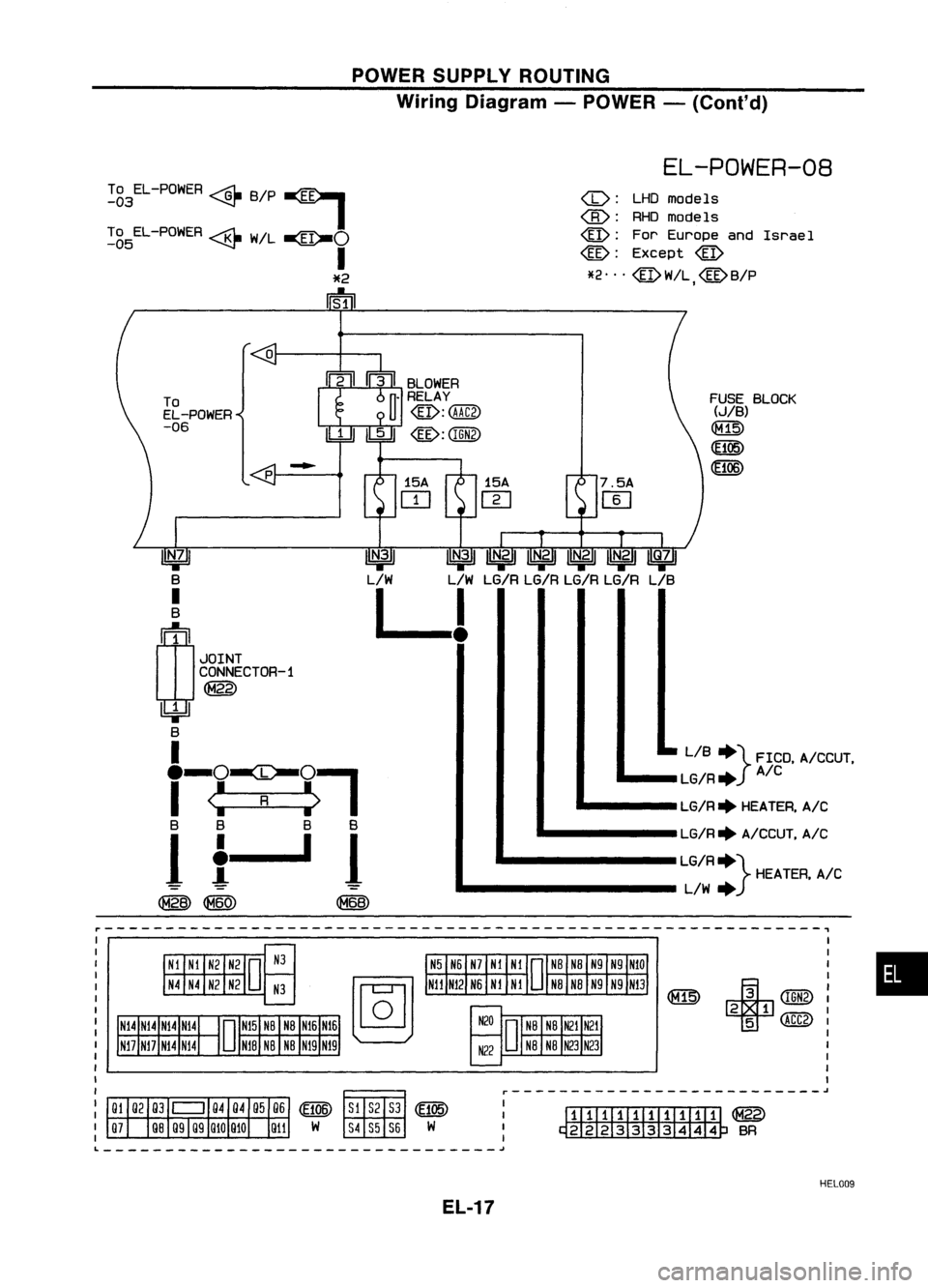
Wiring Diagram -POWER -(ConI' d)
EL-POWER-08
r-----------------------------------------------------------,
•
+
CIGN2)
2 1
5 (ACC2)
FUSE
BLOCK
(..)/B)
(ill)
(105)
7.5A
IT]
@:
ForEurope andIsrael
@:
Except
@
*2'" @W!L @B/P
I
UITIIIIIIIIIill
@
~BR •
LIB +} FICO. A/CCUT •
.. __ LG/R+ A/C
.. ---- LG/R+HEATER, A/C
... ----- LG/R+A/CCUT. A/C
LG/R+} HEATER.A/C
L/W
+
r--------------------------
15A
m
-
o
p
To
EL-POWER
-06
UN.?'
B
I
B
ln
1
JOINT
CONNECTOR-1
@
~
B
I
.
-()~()..,
I
<:
R
:>
I
B B BB
If-II
~~ @
To
EL-POWER ~B/P~
-03 ~
I
~g5EL-POWER ~W/L~()
I
*2
rrm
--------------------------------~
HEL009
EL-17
Page 618 of 1701
HEATEDSEAT
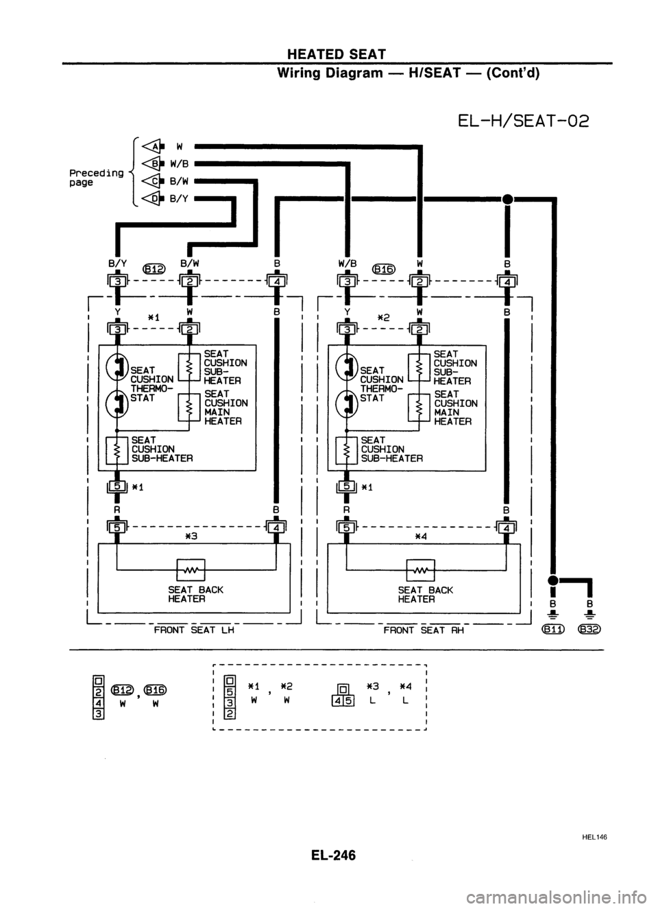
Wiring Diagram -H/SEAT -(Cont'd)
EL-H/SEAT-02
,.
B B
~ ~
~ @)
~W
<@-
W/B------- ....
~B/W---.
-"'1
I
I
B/Y ~ B/W BW/B~ W B
$-----$-------~ $-----$-------~
i-t----t------t, i-t----t------t,
I
Y *1 W B
I
Y*2 W B
I
I
m-----ffl
I
m-----ffl
I
SEAT SEAT
I
CUSHION
I
CUSHION
II
I
SUB-
I
SUB-
HEATER HEATER
SEAT SEAT
I
CUSHION
I
CUSHION
II
I
MAIN
I
MAIN
HEATER HEATER
I I I
I I I
I I I
I I I
I I I
I I....,I
I I I
I
SEATBACK
I
SEATBACK
I
I
HEATER
I
HEATER
I
L: ~L: ~
FRONT SEATLH FRONTSEATRH
Preceding
page
r------------------------~
;2
~,@
4 W W
3
I
I ~
*1 *2
I
5 ,
: 3 W W
I
2
I I
I
J'QL
*3,*4
I
~ LL:
I
I
~------------------------~
HEL146
EL-246
Page 754 of 1701

BASICSERVICE PROCEDURE
Idle Speedllgnition TiminglldleMixtureRatio
Adjustment
PREPARATION
• Make surethatthefollowing partsarein
good order.
(1) Battery
(2) Ignition system
(3) Engine oiland coolant levels
(4) Fuses
(5) ECM harness connector
(6) Vacuum hoses
(7) Airintake system
(Oil filler cap,oillevel gauge, etc.)
(8) Fuel pressure
(9)' Engine compression
(10) Throttle valve
(11) EGR valve operation -For Europe and
Israel andAustralia, andGA15DE M/Tmod-
els
Overall inspection sequence
INSPECTION
(12)
Evaporative emissionsystem
• On models equipped withairconditioner,
checks shouldbecarried outwhile theair
conditioner is"OFF".
• On models equipped withautomatic
transaxle, whenchecking idlespeed, ignition
timing andmixture ratio,checks shouldbe
carried outwhile shiftlever isin
"N"
position.
• When measuring
"CO"
percentage, insert
probe morethan40cm (15.7 in)into tailpipe .•
• Turn offheadlamps, heaterblower, rear
defogger.
• Keep frontwheels pointed straight ahead.
• Make thecheck afterthecooling fanhas
stopped.
Perform diagnostic testmode
1/
(Self-diagnostic results).
Check
&
adjust ignition timing.
Check
&
adjust idlespeed. NG
Repair orreplace.
Check oxygen sensor*1 function.
OK
Check
oxygen sensor*1 har-
ness.
Check CO%.
NG
NG
Repair orreplace harness.
OK Replace oxygensensor*1.
INSPECTION END Check
emission controlparts NGCheck oxygen sensor*1 function. OK
and repair orreplace ifneces-
sary.
*1: Heated oxygen sensor(ForEurope andIsrael, andAustralia AfTmodels)
Oxygen sensor(Except forEurope andIsrael, andAustralia AfTmodels)
EC-35
Page 801 of 1701
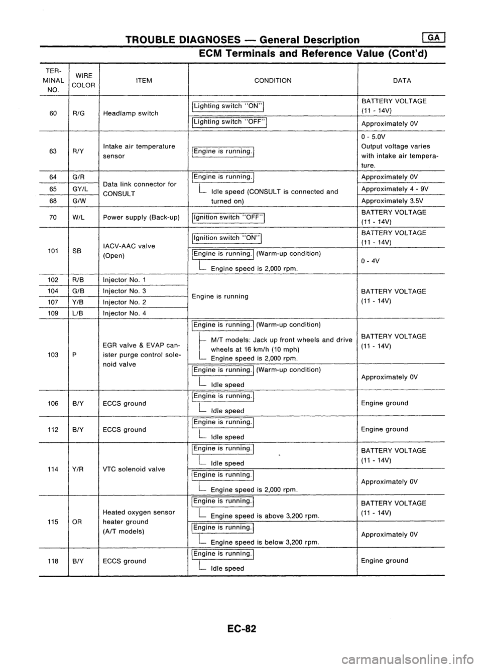
TROUBLEDIAGNOSES -General Description ~
ECM Terminals andReference Value(Conl'd)
TER- WIRE
MINAL COLOR ITEM
CONDITION DATA
NO.
ILightingswitch"ON"I BATTERY
VOLTAGE
60
RIG
Headlamp switch (11
-14V)
ILighting switch"OFF"I
ApproximatelyOV
0- 5.0V
63 RIY Intake
airtemperature
I
Engine isrunning.
I
Output
voltage varies
sensor with
intake airtempera-
ture.
64 GIR
I
Engine isrunning.
I
Approximately
OV
65 GY/L Data
linkconnector for
L
Idle speed (CONSULT isconnected andApproximately
4-9V
CONSULT
68
GIW
turnedon) Approximately
3.5V
I,gnition switch"OFF"
I
BATTERY
VOLTAGE
70
W/L
Powersupply (Back-up)
(11-14V)
Ilgnition switch"ON"I BA
TTERY VOLTAGE
IACV-AAC valve (11
-14V)
101 SS
(Open)
I
Engine isrunning.
I
(Warm-up condition)
L
Engine speedis2,000 rpm. 0-
4V
102 RIB Injector
No.1
104
GIS
InjectorNo.3
BATTERYVOLTAGE
107 YIB InjectorNo.2 Engine
isrunning
(11-14V)
109 LIB Injector
No.4
IEngineisrunning.
I
(Warm-up condition)
~ MIT
models: Jackupfront wheels anddrive BATTERY
VOLTAGE
EGR valve
&
EVAP can-
L
wheels at16 kmlh (10mph) (11
-14V)
103 P
.isterpurge control sole-
Enginespeedis2,000 rpm.
noid valve
IEngineisrunning.
I
(Warm-up condition)
L
Idle speed Approximately
OV
106 BIY ECCSground
I
Engine isrunning.
I
Engineground
L
Idle speed
112 BIY ECCS
ground
I
Engine isrunning.
I
Engineground
L
Idle speed
I Engine isrunning.
I
BATTERYVOLTAGE
L
Idle speed
.
(11-14V)
114 YIR VTCsolenoid valve
I
Engine isrunning.
I
L
Engine speedis2,000 rpm. Approximately
OV
IEngine isrunning.
I
BATTERYVOLTAGE
Heated oxygen sensor
L
Engine speedisabove 3,200rpm. (11
-14V)
115 OR heaterground
IEngine isrunning.
I
(A/T models)
ApproximatelyOV
L
Engine speedisbelow 3,200rpm.
118 SlY ECCS
ground
I
Engine isrunning.
I
Engineground
L
Idle speed
EC-82
Page 805 of 1701
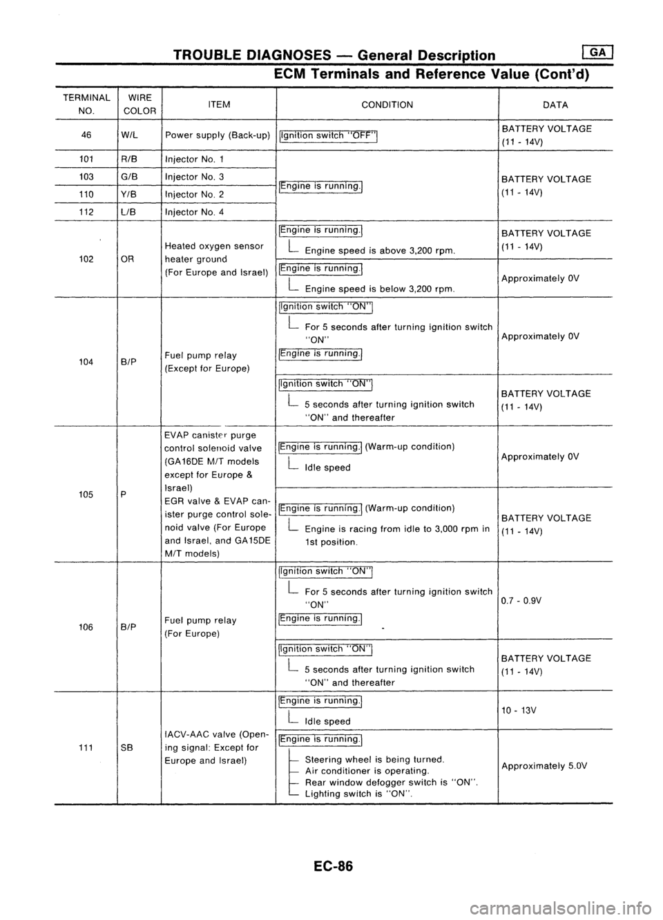
TROUBLEDIAGNOSES -General Description
mJ
ECM Terminals andReference Value(Cont'd)
TERMINAL WIRE
NO. COLOR ITEM
CONDITION DATA
46 WIL Powersupply (Back-up)
Ilgnitionswitch"OFF'" BA
TTERY VOLTAGE
(11 -14V)
101 RIB InjectorNo.1
103
GIB
InjectorNo.3
BATTERYVOLTAGE
110 Y/B InjectorNO.2 IEngine
isrunning./
(11-14V)
112 LIB Injector
NO.4
IEngineisrunning.1
BATTERY VOLTAGE
Heated oxygen sensor
L
Engine speedisabove 3,200rpm. (11
-14V)
102 OR heaterground
(For Europe andIsrael) IEngine
isrunning.1
ApproximatelyOV
L
Engine speedisbelow 3,200rpm.
jlgnition switch"ON"I
L
For 5seconds afterturning ignition switch
"ON" Approximately
OV
104 B/P Fuel
pump relay /Engine
isrunning.1
(Except forEurope)
Ilgnitionswitch"ON"I
BATTERYVOLTAGE
L
5seconds afterturning ignition switch
(11-14V)
"ON" andthereafter
EVAP canister purge
control solenoid valveIEngine
isrunning.1 (Warm-up condition)
(GA16DE
MIT
models
L
Idle speed Approximately
OV
except forEurope
&
105 P Israel)
EGR valve
&
EVAP can-
ister purge control sole-IEngine
isrunning.1 (Warm-up condition)
BATTERYVOLTAGE
noid valve (ForEurope
L
Engine isracing fromidleto3,000 rpmin
(11-14V)
and Israel, andGA15DE
1st position.
MIT
models)
jlgnitionswitch"ON"I
L
For 5seconds afterturning ignition switch
"ON" 0.7
-0.9V
106 SIP Fuel
pump relay IEngine
isrunning.1
(For Europe)
-
Ilgnition switch"ON"I
BATTERYVOLTAGE
L
5seconds afterturning ignition switch
(11-14V)
"ON" andthereafter
IEngine isrunning.1
10-13V
L
Idle speed
IACV-AAC valve(Open-
IEngineisrunning.1
111 5B ingsignal: Exceptfor
Europe andIsrael)
l
51.."" wheel
t,
be'" I,med
Approximately5.0V
Air conditioner isoperating.
Rear window defogger switchis"ON".
Lighting switchis"ON".
EC-86
Page 911 of 1701
I;)
1
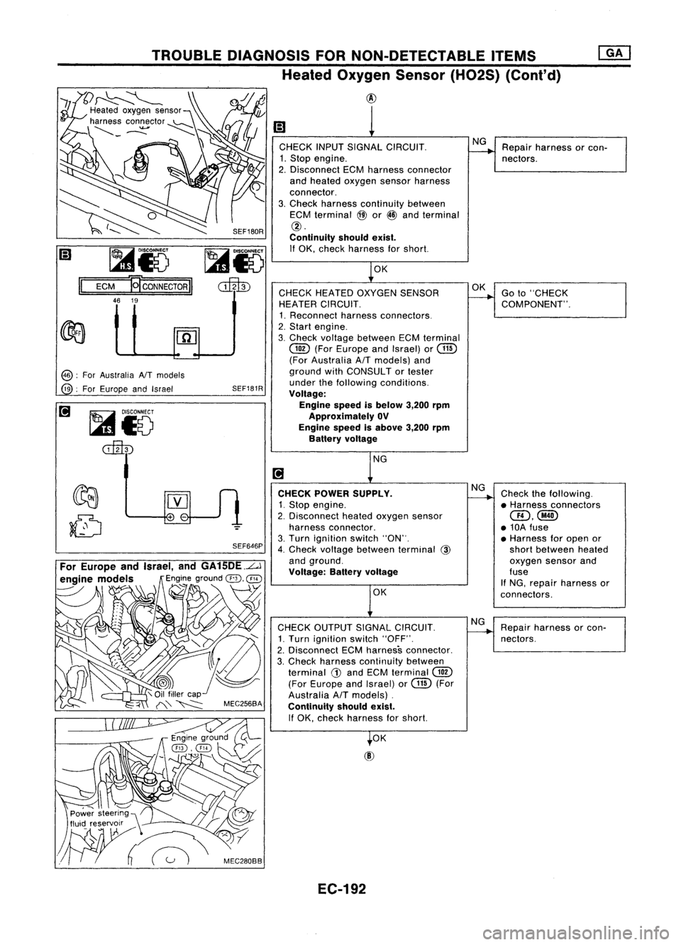
CHECK INPUTSIGNAL CIRCUIT. NG
Repair harness orcon-
1. Stop engine.
--.
nectors.
2. Disconnect ECMharness connector
and heated oxygen sensorharness
connector.
3. Check harness continuity between
ECM terminal
@
or
@
and terminal
@.
Continuity shouldexist.
If OK, check harness forshort.
1
0K
CHECK HEATED OXYGEN SENSOR OK
Goto"CHECK
HEATER CIRCUIT.
--.
COMPONENT".
1. Reconnect harnessconnectors.
2. Start engine.
3. Check voltage between ECMterminal
@
(ForEurope andIsrael) or
@
(For Australia AfTmodels) and
ground withCONSULTor tester
under thefollowing conditions.
Voltage:
Engine speedisbelow 3,200rpm
Approximately OV
Engine speedisabove 3,200rpm
Battery voltage
NG
[!J
CHECK POWER SUPPLY. NG
Check thefollowing.
1. Stop engine.
~
•Harness connectors
2. Disconnect heatedoxygen sensor
aD,@
harness connector. •10A fuse
3. Turn ignition switch"ON".
•Harness foropen or
4. Check voltage between terminal
@
shortbetween heated
and ground. oxygensensorand
Voltage: Batteryvoltage fuse
If NG, repair harness or
OK connectors.
CHECK OUTPUT SIGNALCIRCUIT. NG
Repair harness orcon-
1. Turn ignition switch"OFF".
-----...
nectors.
2. Disconnect ECMharness connector.
3, Check harness continuity between
terminal
G)
and ECM terminal
@
(For Europe andIsrael) orGill (For
Australia
AfT
models) .
Continuity shouldexist.
If OK, check harness forshort.
t
OK
SEF180R
SEF646P
SEF181R
~i5
cilltD
@:
ForAustralia NTmodels
@:
ForEurope andIsrael
TROUBLE
DIAGNOSIS FORNON-DETECTABLE ITEMS
Heated Oxygen Sensor(H02S) (Cont'd)
@
~
~
I;) ~i5
Il
ECM
'QcoNNECTORII
46 19
For Europe andIsrael, andGA15DE.L.J
engine models
Engineground
@,
@
----- \
~ ~
'1
\
.~
,~\ C/
Power steering",
fluid reservoir __\ ~
W~
:'C"",,
EC-192