Page 1136 of 1701

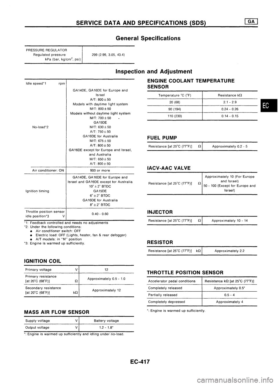
SERVICEDATAANDSPECIFICATIONS (SOS)
General Specifications
PRESSURE REGULATOR
Regulated pressure
kPa (bar, kg/cm
2,
psi) 299
(2.99, 3.05,43.4)
Idle speed'1
rpm
Inspection
andAdjustment
ENGINE COOLANT TEMPERATURE
SENSOR
Temperature
'c
('F) Resistancekn
20 (68) 2.1
-2.9
•
90
(194) 0.24-0.26
110 (230) 0.14-0.15
No-load'2
Air conditioner: ONGA
14DE, GA16DE forEurope and
Israel
AIT: 800:1:50
Models withdaytime lightsystem
MIT: 800:1:50
Models withoutdaytime lightsystem
M/T: 700:1:50
GA15DE
M/T: 630:1: 50
A/T: 750:1: 50
GA 16DE forAustralia
M/T: 675:1: 50
A/T: 800:1:50
GA16DE exceptforEurope andIsrael,
and Australia
M/T: 650:1:50
A/T: 800:1: 50
900 ormore
FUEL
PUMP
Resistance [at25'C (77'F)] n
IACV-AAC VALVE
Approximately
0.2-5
Ignition timing GA
14DE, GA16DE forEurope and
Israel andGA16DE except forAustralia
10':1:2' BTDC
GA15DE
6':1:2' BTDC
GA16DE forAustralia
8':1:2' BTDC Resistance
[at25'C (77'F)) Approximately
10(For Europe
n andIsrael)
50 -100 (Except forEurope and
Israel)
0.40. 0.60
Throttle
position sensor
idle position'3 V
'1: Feedback controlled andneeds noadjustments
'2: Under thefollowing conditions:
• Air conditioner switch:OFF
• Electric load:OFF(Lights, heater,fan
&
rear defogger)
• A/T models: in"N" position
'3: Engine iswarmed upSUfficiently.
IGNITION COIL INJECTOR
Resistance [at25'C (77'F)) n
RESISTOR
Resistance [at25'C (77'F)] kn Approximately
10.14
Approximately 2.2
THROTTLE POSITIONSENSOR
Primary
voltage
Primary resistance
[at 20'C (68'F)]
Secondary resistance
[at 20'C (68'F)]
V
n
kn
12
Approximately 0.5-1.0
Approximately 12 Accelerator
pedalconditions
Completely released
Partially released
Completely depressed Resistance
kn[at25'C (77'F))
Approximately 0.5'
0.5 -4
Approximately 4
MASS AIRFLOW SENSOR
':
Engine iswarmed upsufficiently.
Supply voltage
Output voltage
V
V
Battery
voltage
1.2 -1.8'
': Engine iswarmed upSUfficiently andidling under no-load.
EC-417
Page 1137 of 1701

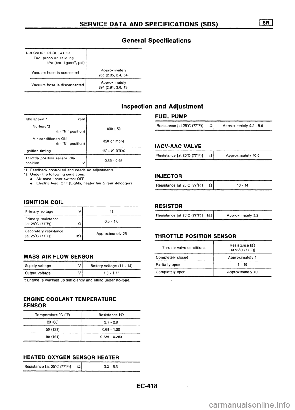
SERVICEDATAANDSPECIFICATIONS (SOS)
General Specifications
PRESSURE REGULATOR
Fuel pressure atidling
kPa (bar, kg/cm
2,
psi)
Vacuum hoseisconnected
Vacuum hoseisdisconnected Approximately
235 (2.35. 2.4.34)
Approxi mately
294 (2.94, 3.0,43)
Idle speed'1
No-load'2 rpm
(in "N" position) 800:1:50
Inspection
andAdjustment
FUEL PUMP
Resistance [at25'C (77'F)] n
Approximately 0.2-5.0
Air conditioner: ON
(in "N" position)
Ignition timing
Throttle position sensoridle
position V850
ormore
IACV-AACVALVE
15':1:2' BTDC
Resistance[at25'C (77'F)] n
0.35 -0.65 Approximately
10.0
'1: Feedback controlled andneeds noadjustments
'2: Under thefollowing conditions:
• Air conditioner switch:OFF
• Electric load:OFF(Lights, heaterfan
&
rear defogger)
IGNITION COIL INJECTOR
Resistance [at25'C (77'F)) n'
1_0_-_1_4 _
RESISTOR
Primary voltage
Primary resistance
[at 25'C (77'F))
V
12
0.5 -1.0 Resistance
[at25'C (77'F)) kn ApproXimately 2.2
Secondary resistance
[at 25'C (77'F))
kn
Approximately
25
THROTTLEPOSITIONSENSOR
MASS AIRFLOW SENSOR
Supply voltage
Output voltage
V
V
Battery
voltage (11-14)
1.3 -1.7'
Throttle
valveconditions
Completely closed
Partially open
Completely open Resistance
kn
[at 25'C (77'F)]
Approximately 1
1 - 10
Approximately 10
': Engine iswarmed upsufficiently andidling under no-load.
ENGINE COOLANT TEMPERATURE
SENSOR
Temperature
'c
('F)
20 (68)
50 (122)
90 (194) Resistance
kn
2.1-2.9
0.68 -1.00
0.236 -0.260
HEATED OXYGEN SENSOR HEATER
Resistance [at25'C (77'F)] n
I
3.3-6.3
EC-418
Page 1147 of 1701
ENGINECOOLING SYSTEM
Cooling Circuit
Reservoir tank
...Thermostat: OPEN
~ Thermostat: CLOSED
•
Water outlet Thermostat
housing
Throttlebody
Intake manifold Heater
SLC9S7AA
LC-9
Page 1169 of 1701
Oilcooler
Cold startdevice
ENGINE
COOLING SYSTEM
Cooling Circuit
_ ======
=.j
Reservoir tank
I
Oil cooler
Heater unit
~ :By-pass passage
LC-31 SLC407
•
Page 1172 of 1701
ENGINECOOLING SYSTEM
Water Pump(Cont'd)
INSPECTION
• Check bodyassembly forrust orcorrosion.
• Check forrough operation duetoexcessive endplay.
SLC760 Thermostat
REMOVAL ANDINSTALLATION
Bolthole
2.5:t0.5(0.098:t 0.020)
die.
\ r
/2.5+0.5
rTfJ ~
(0.098:t 0.020)
die.
SLC564AA
Thermostat
housing
o
a
o
Bolt hole
¥
2.5:t0.5 (0.098:t 0.020)
die.
F2.5+0.5
,-a,
(0.098:t ~.020)die.
From
coldstart device
'I ..
From
01
cooler ..
/
From heater unit~~
2.5+'5
0
:. ••uo.02O)~'28l
Unit: mm(in)
toJ :
N.m (kg-m, ft-Ib)
SEC.
210-211
•Apply liquidgasket towater outlet, thermostat housingand
water inlet.
LC-34
Page 1250 of 1701
TIMINGCHAIN
Removal (ConI'd)
17. Remove timingchainguide.
18. Remove camshaft sprockets.
19. Remove camshafts, camshaftbrackets, oiltubes andbaffle
plate.
•
Loosen innumerical order.
SEM7870A
20.Remove startermotor.
21. Remove thefollowing waterhoses.
• Water hoseforcylinder block.
• Water hosesfromheater.
22. Remove knocksensor harness connector.
EM-71
Page 1256 of 1701
MethodA
Method B 90+5degrees
-0
Engine Paint
mark
front
:0
118
~
(12,87)
Plasticzone
EO
78
0,
(8,58)
~
E
39
z
(4,29)
SEM074DATIMING
CHAIN
[]B]
Installation (Cont'd)
@
Method A:Turn allbolts 90to95 degrees clockwise with
Tool orsuitable anglewrench.
Method B:
If
angle wrench isnot available, dothe follow-
ing. Mark theside ofall bolts withpaint marks
facing thefront ofthe engine. Thenturnthem 90
to 95 degrees clockwise.
CD
Turn allbolts 90to95 degrees clockwise. •
@
Ensure thatpaint mark oneach boltfaces therear ofthe
engine. (Method Bonly)
Do not turn anybolt 180to190 degrees clockwise allatonce.
Tightening torqueN'm(kg-m, ft-Ib)
@
39(4.0, 29)
@
78(8.0, 58)
@
0(0,0)
@
34-44 (3.5 -4.5, 25-33)
@
90-95 degrees (90degree preferred)
CD
90
-95 degrees (90degree preferred)
14. Install cylinder headoutside bolts.
15. Install thefollowing waterhoses.
• Water hoseforcylinder block.
• Water hosesforheater.
16. Install knocksensor harness connector.
EM-77
Page 1323 of 1701
Unit:mm(in) 183.0(7.205)
SEM707DCYLINDER
BLOCK
Preparation
• Drill ahole intotheattachment (KV10108101).
Disassembly
PISTON ANDCRANKSHAFT
1. Place engine onawork stand.
2. Drain coolant andoil.
3. Remove timingbelt.
4. Remove waterpump.
5. Remove oilpan andoilpump.
6. Remove cylinder head.
7. Remove pistonswithconnecting rods.
When disassembling pistonandconnecting rod,heat piston to
60 to70°C (140to158°F) oruse piston pinpress standatroom
temperature.
Heater
SEM360D
8.Remove bearingcapand crankshaft.
Place thebearings andcaps intheir proper order.
Upper bearings (cylinderblockside)haveoilgroove.
Loosen innumerical order.
SEM564A
SEM291
9.
Remove pistonringswithatool.
EM-144