Page 1360 of 1701
PRECAUTIONS
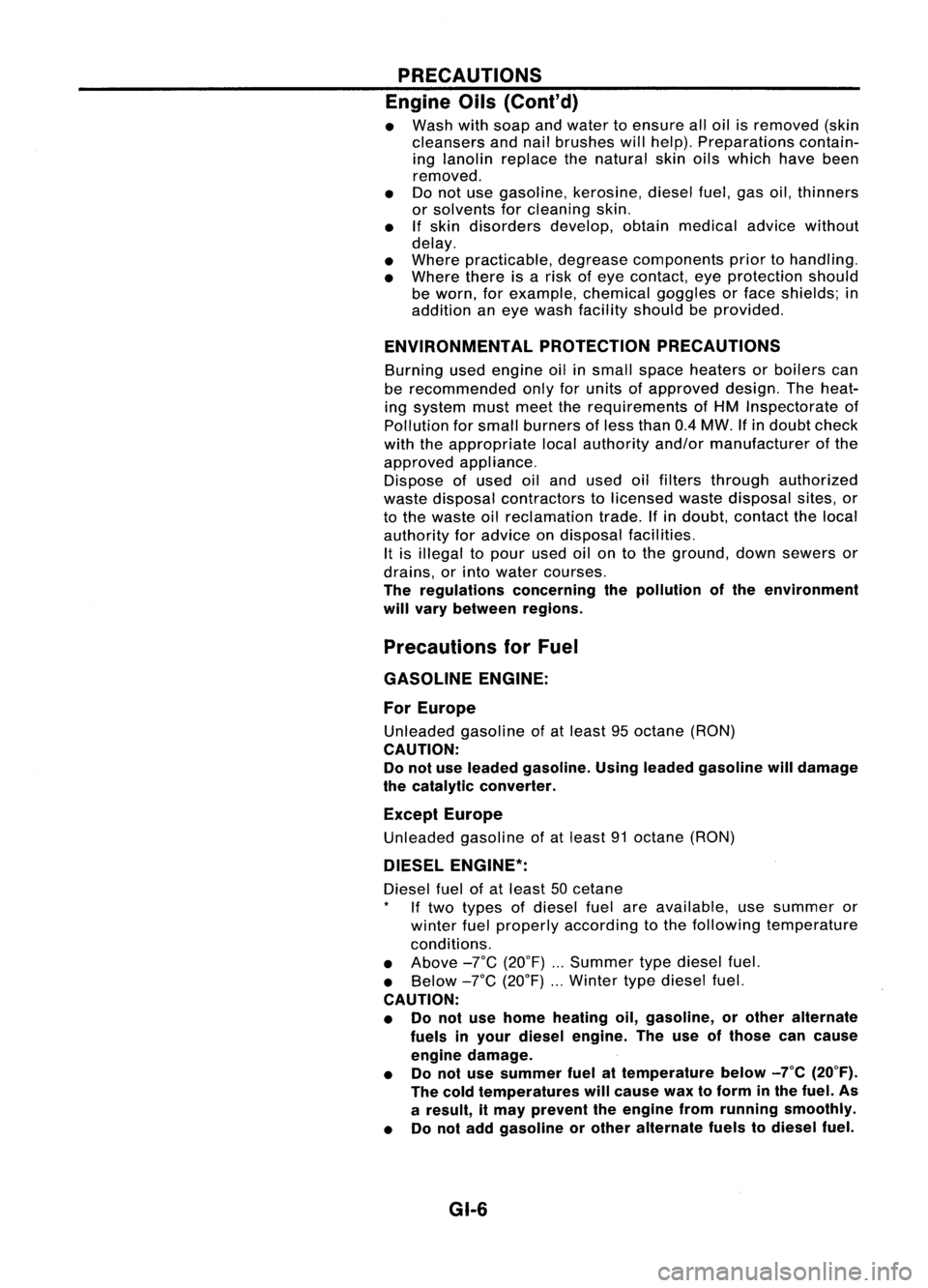
Engine Oils(ConI' d)
• Wash withsoap andwater toensure alloil isremoved (skin
cleansers andnailbrushes willhelp). Preparations contain-
ing lanolin replace thenatural skinoilswhich havebeen
removed.
• Donot use gasoline, kerosine, dieselfuel,gasoil,thinners
or solvents forcleaning skin.
• If
skin disorders develop,obtainmedical advicewithout
delay.
• Where practicable, degreasecomponents priortohandling.
• Where thereisarisk ofeye contact, eyeprotection should
be worn, forexample, chemicalgogglesorface shields; in
addition aneye wash facility should beprovided.
ENVIRONMENTAL PROTECTIONPRECAUTIONS
Burning usedengine oilinsmall space heaters orboilers can
be recommended onlyforunits ofapproved design.Theheat-
ing system mustmeettherequirements ofHM Inspectorate of
Pollution forsmall burners ofless than 0.4MW. Ifin doubt check
with theappropriate localauthority and/ormanufacturer ofthe
approved appliance.
Dispose ofused oiland used oilfilters through authorized
waste disposal contractors tolicensed wastedisposal sites,or
to the waste oilreclamation trade.Ifin doubt, contact thelocal
authority foradvice ondisposal facilities.
It is illegal topour used oilontothe ground, downsewers or
drains, orinto water courses.
The regulations concerningthepollution ofthe environment
will vary between regions.
Precautions forFuel
GASOLINE ENGINE:
For Europe
Unleaded gasolineofat least 95octane (RON)
CAUTION: Do not use leaded gasoline. Usingleaded gasoline willdamage
the catalytic converter.
Except Europe
Unleaded gasolineofat least 91octane (RON)
DIESEL ENGINE*:
Diesel fuelofat least 50cetane
If two types ofdiesel fuelareavailable, usesummer or
winter fuelproperly according tothe following temperature
conditions.
• Above -rc(20°F) Summer typediesel fuel.
• Below
-rc
(20°F) Wintertypediesel fuel.
CAUTION:
• Donot use home heating oil,gasoline, orother alternate
fuels inyour diesel engine. Theuseofthose cancause
engine damage.
• Donot use summer fuelattemperature below_7°C(20°F).
The cold temperatures willcause waxtoform inthe fuel. As
a result, itmay prevent theengine fromrunning smoothly.
• Donot add gasoline orother alternate fuelstodiesel fuel.
GI-6
Page 1371 of 1701
HOWTOREAD WIRING DIAGRAMS
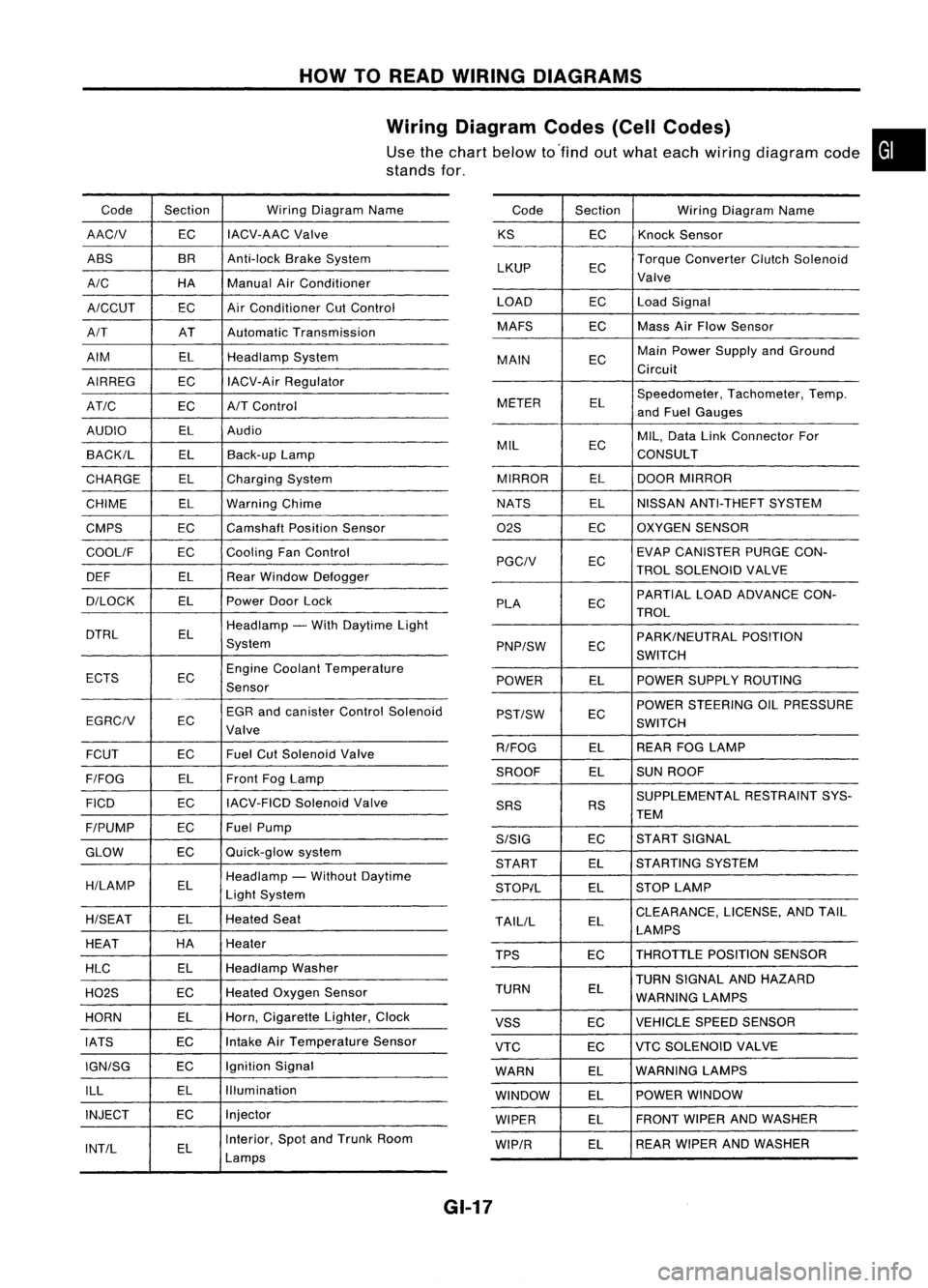
Wiring Diagram Codes(CellCodes)
Use thechart below to'find outwhat each wiring diagram code•
stands for,
Code Section WiringDiagram Name
AACIV ECIACV-AAC
Valve
ABS BR
Anti-lock BrakeSystem
A/C HAManualAirConditioner
A/CCUT ECAir
Conditioner CutControl
A/T ATAutomatic Transmission
AIM ELHeadlamp System
AIRREG ECIACV-Air Regulator
AT/C ECA/TControl
AUDIO ELAudio
BACK/L ELBack-up Lamp
CHARGE ELCharging System
CHIME ELWarning Chime
CMPS EC
Camshaft PositionSensor
COOllF ECCooling
FanControl
DEF ELRearWindow Defogger
D/LOCK ELPowerDoorLock
DTRL ELHeadlamp
-With Daytime Light
System
ECTS ECEngine
Coolant Temperature
Sensor
EGR andcanister ControlSolenoid
EGRCIV EC
Valve
FCUT ECFuel
CutSolenoid Valve
F/FOG ELFront
FogLamp
FICO ECIACV-FICD
SolenoidValve
F/PUMP ECFuel
Pump
GLOW ECQuick-glow
system
H/LAMP ELHeadlamp
-Without Daytime
Light System
H/SEAT ELHeated
Seat
HEAT HA
Heater
HLC ELHeadlamp
Washer
H02S ECHeated
Oxygen Sensor
HORN ELHorn,
Cigarette Lighter,Clock
IATS ECIntake
AirTemperature Sensor
IGN/SG ECIgnition
Signal
ILL ELIllumination
INJECT ECInjector
INT/L ELInterior,
SpotandTrunk Room
Lamps Code
Section WiringDiagram Name
KS ECKnock
Sensor
LKUP ECTorque
Converter ClutchSolenoid
Valve
LOAD ECLoadSignal
MAFS ECMass
AirFlow Sensor
MAIN ECMain
Power Supply andGround
Circuit
METER ELSpeedometer,
Tachometer,Temp.
and Fuel Gauges
MIL ECMIL,
Data LinkConnector For
CONSULT
MIRROR ELDOOR
MIRROR
NATS ELNISSAN
ANTI-THEFT SYSTEM
02S ECOXYGEN
SENSOR
EC EVAP
CANISTER PURGECON-
PGCIV TROLSOLENOID VALVE
PLA ECPARTIAL
LOADADVANCE CON-
TROL
EC PARK/NEUTRAL
POSITION
PNP/SW SWITCH
POWER ELPOWER
SUPPLY ROUTING
POWER STEERING OILPRESSURE
PST/SW EC
SWITCH
R/FOG ELREAR
FOGLAMP
SROOF ELSUN
ROOF
SUPPLEMENTAL RESTRAINTSYS-
SRS RS
TEM
S/SIG ECST
ART SIGNAL
START ELSTARTING
SYSTEM
STOP/L ELSTOP
LAMP
TAllIL ELCLEARANCE,
LICENSE,ANDTAIL
LAMPS
TPS ECTHROTTLE
POSITIONSENSOR
TURN SIGNAL ANDHAZARD
TURN EL
WARNING LAMPS
VSS ECVEHICLE
SPEEDSENSOR
VTC ECVTC
SOLENOID VALVE
WARN ELWARNING
LAMPS
WINDOW ELPOWER
WINDOW
WIPER ELFRONT
WIPERANDWASHER
WIP/R ELREAR
WIPER ANDWASHER
GI-17
Page 1399 of 1701
SAEJ1930 TERMINOLOGY LIST
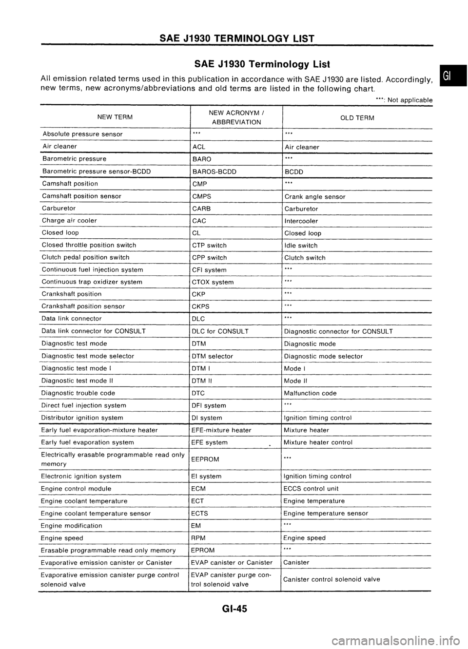
SAE J1930 Terminology List
All emission relatedtermsusedinthis publication inaccordance withSAE J1930 arelisted. Accordingly,
new terms, newacronyms/abbreviations andoldterms arelisted inthe following chart.
"':Not applicable
NEW TERM NEW
ACRONYM /
ABBREVIATION OLD
TERM
Absolute pressure sensor
'" '"
Air cleaner
ACLAircleaner
Barometric pressure
BARO
."
Barometric pressuresensor-BCDD
BAROS-BCDD BCDD
Camshaft position
CMP
'"
Camshaft positionsensor
CMPS Crankanglesensor
Carburetor CARBCarburetor
Charge aircooler
CACIntercooler
Closed loop
CLClosedloop
Closed throttle position switch
CTPswitch
Idleswitch
Clutch pedalposition switch
CPPswitch Clutchswitch
Continuous fuelinjection system
CFIsystem
'"
Continuous trapoxidizer system
CTOXsystem
...
Crankshaft position
CKP
'"
Crankshaft positionsensor
CKPS
~.**
Data linkconnector
DLC
,
..
Data linkconnector forCONSULT
DLCforCONSULT DiagnosticconnectorforCONSULT
Diagnostic testmode
DTMDiagnosticmode
Diagnostic testmode selector
DTMselector Diagnosticmodeselector
Diagnostic testmode I
DTMI ModeI
Diagnostic testmode II
DTMII ModeII
Diagnostic troublecode
DTC Malfunctioncode
Direct fuelinjection system
DFIsystem
..
,
Distributor ignitionsystem DIsystem Ignitiontimingcontrol
Early fuelevaporation-mixture heater
EFE-mixtureheater Mixture
heater
Early fuelevaporation system
EFEsystem
.
Mixture
heatercontrol
Electrically erasableprogrammable readonly
EEPROM
'"
memory
Electronic ignitionsystem EIsystem Ignitiontimingcontrol
Engine control module ECMECCScontrol unit
Engine coolant temperature ECTEngine
temperature
Engine coolant temperature sensor ECTS Engine
temperature sensor
Engine modification EM
'"
Engine speed RPM
Enginespeed
Erasable programmable readonlymemory EPROM
'"
Evaporative emissioncanisterorCanister EVAP
canister orCanister Canister
Evaporative emissioncanisterpurgecontrol EVAP
canister purgecon-
Canister controlsolenoid valve
solenoid valve trol
solenoid valve
GI-45
•
Page 1403 of 1701
HEATER
&
AIR CONDITIONER
SECTION
HA
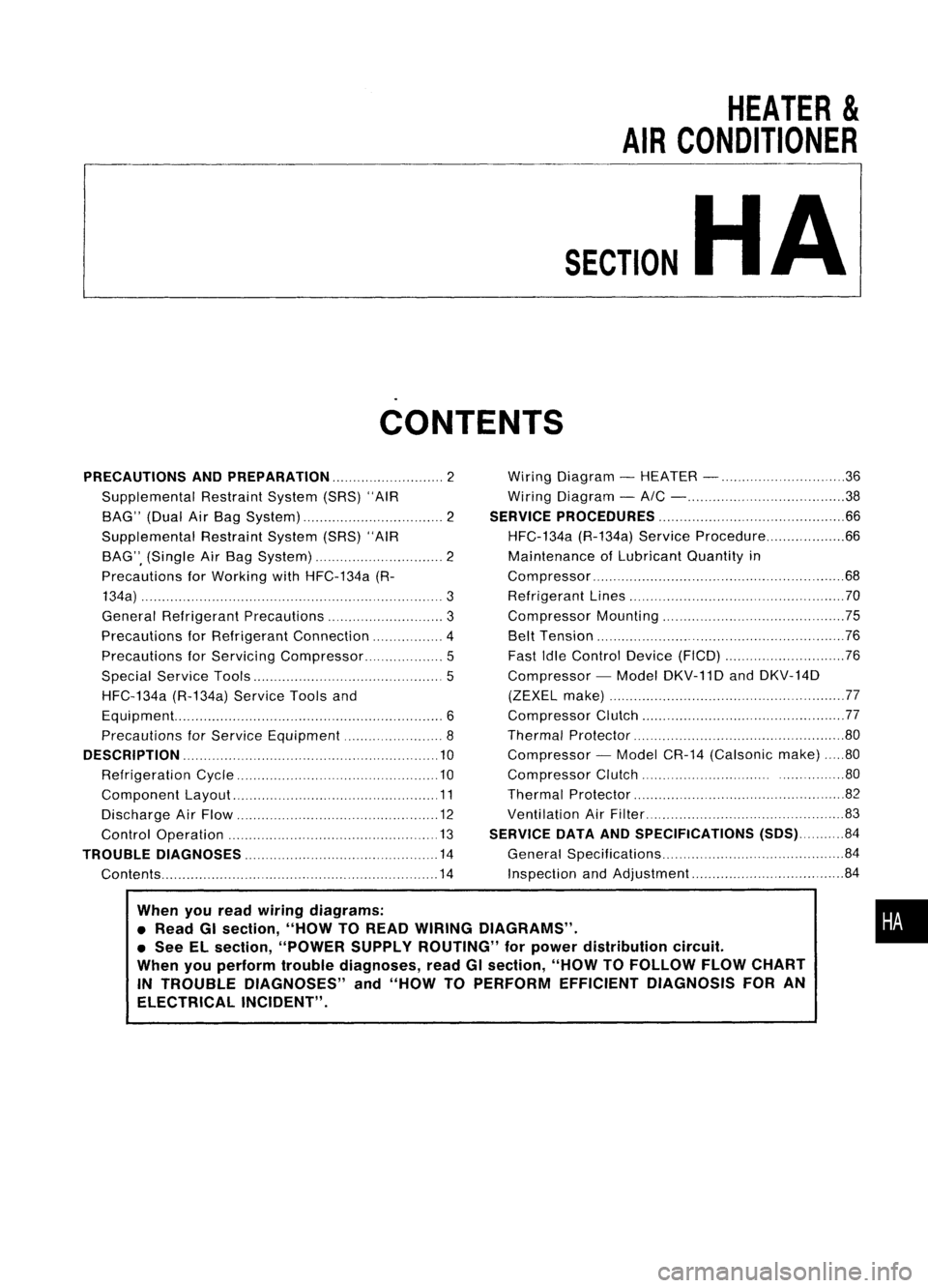
CONTENTS
When youread wiring diagrams:
• Read GIsection, "HOWTOREAD WIRING DIAGRAMS" .
• See ELsection, "POWER SUPPLYROUTING" forpower distribution circuit.
When youperform troublediagnoses, readGIsection, "HOWTOFOLLOW FLOWCHART
IN TROUBLE DIAGNOSES" and"HOW TOPERFORM EFFICIENT DIAGNOSIS FORAN
ELECTRICAL INCIDENT".
PRECAUTIONS
ANDPREPARATION 2
Supplemental RestraintSystem(SRS)"AIR
BAG" (DualAirBag System) 2
Supplemental RestraintSystem(SRS)"AIR
BAG", (Single AirBag System) 2
Precautions forWorking withHFC-134a (R-
134a) 3
General Refrigerant Precautions 3
Precautions forRefrigerant Connection 4
Precautions forServici ngCompressor. ..5
Special Service Tools 5
HFC-134a (R-134a)ServiceToolsand
Equipment. 6
Precautions forService Equipment 8
DESCRIPTION 10
Refrigeration Cycle .10
Component Layout 11
Discharge AirFlow 12
Control Operation 13
TROUBLE DIAGNOSES 14
Contents 14Wiring
Diagram -HEATER - 36
Wiring Diagram -
AIC - 38
SERVICE PROCEDURES 66
HFC-134a (R-134a)ServiceProcedure 66
Maintenance ofLubricant Quantityin
Compressor 68
Refrigerant Lines 70
Compressor Mounting 75
Belt Tension 76
Fast IdleControl Device(FICO) 76
Compressor -Model DKV-11D andDKV-14D
(ZEXEL make) 77
Compressor Clutch 77
Thermal Protector 80
Compressor -Model CR-14 (Calsonic make)80
Compressor Clutch ..80
Thermal Protector 82
Ventilation AirFilter 83
SERVICE DATAANDSPECIFICATIONS (SDS)84
General Specifications 84
Inspection andAdjustment 84
•
Page 1414 of 1701
DESCRIPTION
Discharge AirFlow
@ Todefroster
Floor
Defroster
.... ;Air passed through heatercore
<$=::I :
Mixed air(...
+
<;::::J )
<:;:::::J ;
Air not passed through heatercore
This
illustration isfor LHD models.
The layout forRHD models issymmetrically opposite.
Ventilator
door
CD;
Ventilation
@:
Defroster
@; Fool
Bi-Ievel
(~ switch"OFF")
RHA313F
HA-12
Page 1416 of 1701
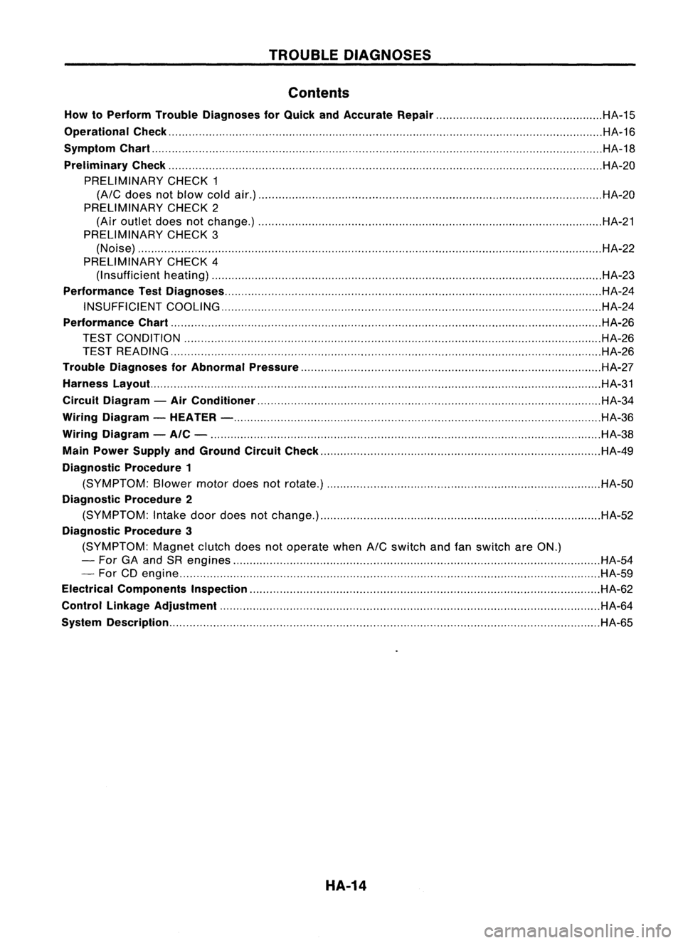
TROUBLEDIAGNOSES
Contents
How toPerform TroubleDiagnoses forQuick andAccurate Repair HA-15
Operational Check HA-16
Symptom Chart HA-18
Preliminary Check HA-20
PRELIMINARY CHECK1
(A/C
does notblow coldair.) HA-20
PRELIMINARY CHECK2
(Air outlet doesnotchange.) HA-21
PRELIMINARY CHECK3
(Noise) HA-22
PRELIMINARY CHECK4
(I nsufficient heating) HA-23
Performance TestDiagnoses HA-24
INSUFFICIENT COOLING HA-24
Performance Chart HA-26
TEST CONDITION HA-26
TEST READING HA-26
Trouble Diagnoses forAbnormal Pressure HA-27
Harness Layout. HA-31
Circuit Diagram -Air Conditioner HA-34
Wiring Diagram -HEATER - HA-36
Wiring Diagram -AIC - HA-38
Main Power Supply andGround CircuitCheck HA-49
Diagnostic Procedure1
(SYMPTOM: Blowermotordoesnotrotate.) HA-50
Diagnostic Procedure2
(SYMPTOM: Intake doordoes notchange.) HA-52
Diagnostic Procedure3
(SYMPTOM: Magnetclutchdoesnotoperate when
A/C
switch andfanswitch areON.)
- For GAand SRengines HA-54
- For CDengine HA-59
Electrical Components Inspection HA-62
Control Linkage Adjustment HA-64
System Description HA-65
HA-14
Page 1425 of 1701
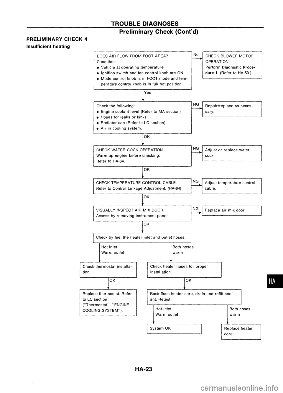
PRELIMINARY CHECK4
Insufficient heating TROUBLE
DIAGNOSES
Preliminary Check(Cont'd)
DOES AIRFLOW FROM FOOTAREA?
Condition:
• Vehicle atoperating temperature .
• Ignition switchandfancontrol knobareON.
• Mode control knobisin FOOT modeandtem-
perature controlknobisinfull hotposition.
Check thefollowing:
• Engine coolant level(Refer toMA section)
• Hoses forleaks orkinks
• Radiator cap(Refer toLC section)
• Air incooling system.
CHECK WATER COCKOPERATION.
Warm upengine before
checking.
Refer toHA-64.
OK
CHECK TEMPERATURE CONTROLCABLE.
Refer toControl Linkage Adjustment. (HA-64)
VISUALLY INSPECTAIRMIX DOOR.
Access byremoving instrument panel.
OK
Check byfeel theheater inletandoutlet hoses.
No
NG
NG
NG
NG
CHECK
BLOWER MOTOR
OPERATION.
Perform
Diagnostic Proce-
dure 1.
(Refer toHA-50.)
Repair/replace asneces-
sary .
Adjust orreplace water
cock.
Adjust temperature control
cable.
Replace airmix door.
Hot inlet
Warm outlet
Check thermostat installa-
tion.
OK
Both
hoses
warm
Check heater hosesforproper
installation.
OK
•
Back
flush heater core,drain andrefill cool-
ant. Retest.
Replace
thermostat. Refer
to LC section
("Thermostat", "ENGINE
COOLING SYSTEM"). Hot
inlet
Warm outlet
System OK
HA-23
Both
hoses
warm
Replace heater
core.
Page 1438 of 1701
TROUBLEDIAGNOSES
Wiring Diagram -HEATER -
HA-HEATER-01
<0:
LHOmodels
Refer toEL-POWER.
(8):
RHOmodels
@:
ForEurope andIsrael
@:
Except@
t
LIB
~
~~~~ST""
L/W L/YL/R
.,--I-~r=t
r
RIG.
To
EL-m
t
L/WL/YL!R LIBRIG
I
:4
II
:31 12~1
Ii2'nJ n1=iI
FAN
SWITCH
@
ILL. ~
~ ~
B B
~ol __
1
I
I I
<
------.~o--l
JOINT
B CONNECTOR-4
1
Li t
J
Lt
1
B
{J
gj.
B~Next page
\~
~/
\~
~
~/
<0
FUSE
15A BLOCK
T
(JIB)
L..:..J ~
IN31
•
L!W L/W
L.l
I
L/W
~1
M
BLOWER
MOTOR
~
I!.j.JJ
LIB
~--------------------,
i~@~~:
I~W 2Wi
I I
I I
L
~
l1IillIITillIil
~
~P
Refer
tolast page
(Foldout page).
~
HHA012
HA-36