Page 912 of 1701
TROUBLEDIAGNOSIS FORNON-DETECTABLE ITEMS
Heated Oxygen Sensor(H02S)(Cont'd)
@
Loosen andretighten engineground
screws.
OK
CHECK COMPONENT
(Heated oxygensensorheater).
Refer to"COMPONENT INSPECTION"
below.
OK
Disconnect andreconnect harnesscon-
ne~tors inthe circuit. Thenretest.
Trouble isnot fixed.
Check ECMpinterminals fordamage
or the connection ofECM harness con-
nector. Reconnect ECMharness con-
nector andretest.
Troubleisnot fixed.
Replace heatedoxygen sensor.
COMPONENT INSPECTION NG
Replace heatedoxygen
sensor.
•
DISCONNECT
I~J
00
SEF586Q
Heated
oxygen sensorheater
Check resistance betweenterminals
@
and
CD.
Resistance: 2.3-4.3Q at25°C (77°F)
Check continuity betweenterminals @and
CD,
@
and @.
Continuity shouldnotexist.
If NG, replace theheated oxygen sensor.
CAUTION:
• Discard anyoxygen sensorwhichhasbeen dropped from
a height ofmore than0.5m(19.7 in)onto ahard surface
such asaconcrete floor;useanew one.
EC-193
Page 951 of 1701

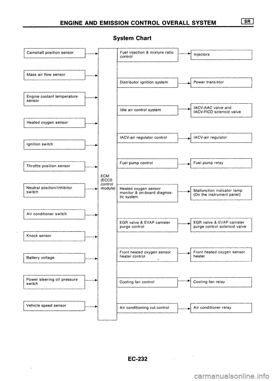
ENGINEANDEMISSION CONTROLOVERALLSYSTEM
System Chart
Camshaft positionsensor Fuel
injection
&
mixture ratio
•
I
I
control Injectors
Mass airflow sensor
I
Distributorignitionsystem
r
~1
Power transistor
Engine coolant temperature
.
sensor
I
IACV-AAC valveand
Idle aircontrol system
IACV-FICDsolenoidvalve
Heated oxygen sensor
I
IACV-airregulator control
~--..j
IACV-air regulator
I
Ignition switch
I
I
Throttle position sensor
~-+
Fuel
pump control Fuel
pump relay
ECM
(ECCS
control
Neutral position/Inhibitor
.
module) Heatedoxygen sensor
switch monitor
&
on-board diagnos-
~-+
Malfunction
indicatorlamp
tic system (On
theinstrument panel)
I
Air conditioner switch
t~
EGRvalve
&
EVAP canister
1---+
EGR
valve
&
EVAP canister
purge control purge
control solenoid valve
Knock sensor
.....
Frontheated oxygen sensor Front
heated oxygen sensor
Battery voltage
.
heater
control heater
I
.
Power steering oilpressure
~
Coolingfancontrol
--
Cooling
fanrelay
switch
Vehicle speedsensor
.....
Airconditioning cutcontrol Air
conditioner relay
EC-232
Page 962 of 1701

BASICSERVICE PROCEDURE
Idle Speedllgnition TiminglldleMixtureRatio
Adjustment
PREPARATION
• Make surethatthefollowing partsarein
good order.
(1) Battery
(2) Ignition system
(3) Engine oiland coolant levels
(4) Fuses
(5) ECM harness connector
(6) Vacuum hoses
(7) Airintake system
(Oil filler cap,oillevel gauge, etc.)
(8) Fuel pressure
(9) Engine compression
(10) Throttle valve
Overall inspection sequence
INSPECTION
•
•
•
•
•
•
On
models equipped withairconditioner,
checks shouldbecarried outwhile theair
conditioner is"OFF".
On models equipped withautomatic
transaxle, whenchecking idlespeed, ignition
timing andmixture ratio,checks shouldbe
carried outwhile shiftlever isin "N" position.
When measuring "CO"percentage, insert
probe morethan40cm (15.7 in)into tailpipe.
Turn offheadlamps, heaterblower, rear
defogger. Keep frontwheels pointed straight ahead.
Make thecheck afterthecooling fanhas
stopped.
•
Perform diagnostic testmode II
(Self-diagnostic results).
OK
Check
&
adjust ignition timing.
Check
&
adjust idlespeed.
Check heated oxygen sensor
function. NG
Repair orreplace.
NG Check heated oxygen sensor
harness. NG
Repair orreplace harness.
OK OK
Check CO%. OKReplace heatedoxygen sensor.
NG
INSPECTION END Check
emission controlparts
and repair orreplace ifneces-
sary.
EC-243
NG
Check heated oxygen sensor
function.
OK
Page 1004 of 1701
![NISSAN ALMERA N15 1995 Service Manual TROUBLEDIAGNOSIS -General Description
[]K]
ECM Terminals andReference Value(Cont'd)
'Data arereference values.
TERMINAL WIRE
ITEM CONDITION
'DATA
NO. COLOR
Ilgnitionswitch"ON"I
NISSAN ALMERA N15 1995 Service Manual TROUBLEDIAGNOSIS -General Description
[]K]
ECM Terminals andReference Value(Cont'd)
'Data arereference values.
TERMINAL WIRE
ITEM CONDITION
'DATA
NO. COLOR
Ilgnitionswitch"ON"I](/manual-img/5/57349/w960_57349-1003.png)
TROUBLEDIAGNOSIS -General Description
[]K]
ECM Terminals andReference Value(Cont'd)
'Data arereference values.
TERMINAL WIRE
ITEM CONDITION
'DATA
NO. COLOR
Ilgnitionswitch"ON"I
L
For 5seconds afterturning ignition switch
"ON" Approximately
OV
104 B/P Fuelpump relay !Engine
isrunning.1
Ilgnition switch"ON"I
BATTERY VOLTAGE
L
5seconds afterturning ignitionswitch
(11-14V)
"ON" andthereafter
IEngine isrunning.1
0.6-0.8V
EGR valve
&
EVAP
.L
Engine speedis4,000 rpm.
105 P canisterpurgecontrol
solenoid valve IEngine
isrunning.1
BATTERYVOLTAGE
L
Idle speed (11
-14V)
107 IEngine
isrunning.j
B/Y ECCSground
L
Engine
ground
108 Idlespeed
!Engine isrunning.1
Approximately0.2V
L
Engine speedisbelow 3,200rpm.
Heated oxygen sensor
111 OR
heater IEngineisrunning.1
BATTERY VOLTAGE
L
Engine speedisabove 3,200rpm. (11
-14V)
IEngine isrunning.\
11-14V
L
Idle speed
113 SB IACV-AAC
valve lEngine
isrunning.1
~ Sle«;ng wheel;,be;ng I"med
2-11V
Air conditioner isoperating.
Rear window defogger switchis"ON".
Lighting switchis"ON".
!Engine isrunning.1
ApproximatelyOV
Torque converter
L
Idle speed
115 P/B clutch
solenoid valve
IEngineisrunning.1 (Warm-up condition)
(A/T
models)
L
Vehicle speedis60 km/h (37MPH) or BA
TTERY VOLTAGE
(11 -14V)
more in"D" position
116 BIY ECCS
ground IEngine
isrunning.1
Engineground
L
Idle speed
EC-285
•
Page 1051 of 1701
TROUBLEDIAGNOSIS FORNON-DETECTABLE ITEMS
Idle AirControl Valve(IACV)-Air Regulator
SYSTEM DESCRIPTION
Camshaft positionsensor
Ignition switch Engine
speed
Start signal ECM
(ECCS
control
module) IACV-air
regulator
The IACV-air regulator iscontrolled bythe ECM
at the same timeasfuel pump ON-OFF control.
Condition
Ignition switchisturned to"ON"
Engine running andcranking
When engine isstopped
Except asshown above IACV-air
regulator
operation
Operates for5
seconds
Operates
OFF in1second
OFF
Bimetal
...
Air flow
SEF095K COMPONENT
DESCRIPTION
IACV-air regulator providesanair bypass whentheengine ;s
cold forafast idleduring warm-up.
A bimetal, heaterandrotary shutter arebuilt intotheIACV-air
regulator. Whenthebimetal temperature islow, theairbypass
port opens. Asthe engine startsandelectric currentflows
through aheater, thebimetal beginstoturn theshutter toclose
the bypass port.Theairpassage remainscloseduntilthe
engine stopsandthebimetal temperature drops.
EC-332
Page 1082 of 1701

TROUBLEDIAGNOSIS FORNON-DETECTABLE ITEMS
Heated Oxygen Sensor(H02S)(Cont'd)
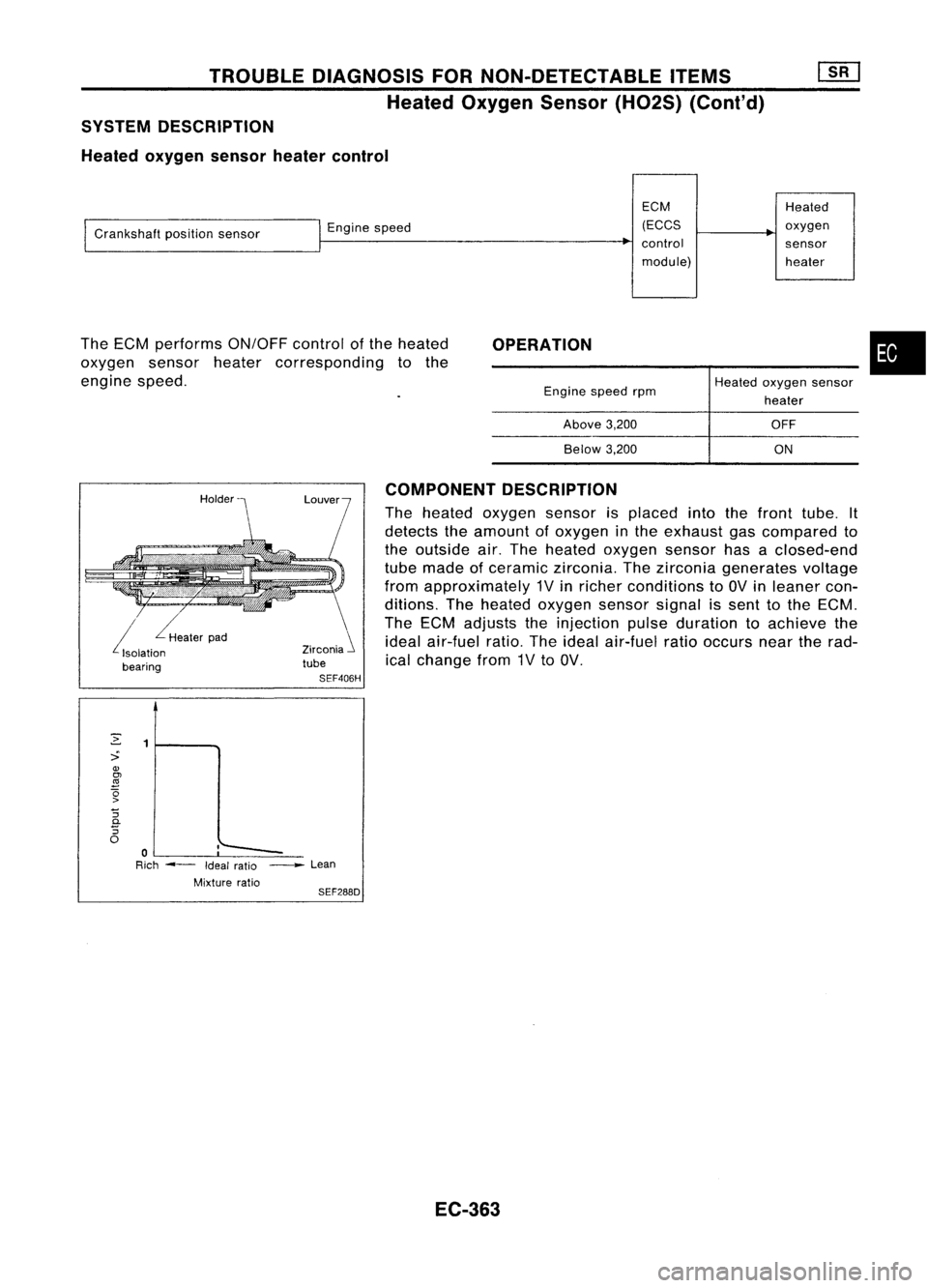
SYSTEM DESCRIPTION
Heated oxygen sensorheatercontrol
ECMHeated
I
Crankshaft positionsensor
I
Engine speed (ECCS
~
oxygen
~
control sensor
module) heater
OPERATION •
--~-
The
ECM performs ON/OFFcontrolofthe heated
oxygen sensorheatercorresponding tothe
engine speed.
Enginespeedrpm
Above 3,200
Below 3,200
Heated
oxygen sensor
heater
OFF
ON
i
Heaterpad
Isolation
bearing Zirconia
i
tube
SEF406H COMPONENT
DESCRIPTION
The heated oxygen sensorisplaced intothefront tube. It
detects theamount ofoxygen inthe exhaust gascompared to
the outside air.The heated oxygen sensorhasaclosed-end
tube made ofceramic zirconia. Thezirconia generates voltage
from approximately 1Vinricher conditions to
av
inleaner con-
ditions. Theheated oxygen sensorsignalissent tothe ECM.
The ECM adjusts theinjection pulseduration toachieve the
ideal air-fuel ratio.Theideal air-fuel ratiooccurs neartherad-
ical change from1Vto
av.
2
1
::>
OJ
~
(5
>
"5
c.
"5
0
:'--
0
-
Rich ---
Ideal
ratio _
Lean
Mixture ratio
SEF288D
EC-363
Page 1084 of 1701

TROUBLEDIAGNOSIS FORNON-DETECTABLE ITEMS
Heated Oxygen Sensor(H02S) (Cont'd)
•
Repair harness orcon-
nectors. Go
to"CHECK
COMPONENT".
Check thefollowing.
• Harness connectors
aD,@
• 10A
fuse
• Harness foropen or
short between heated
oxygen sensorand
fuse
If NG, repair harness or
connectors.
OK
NG
NG
OK
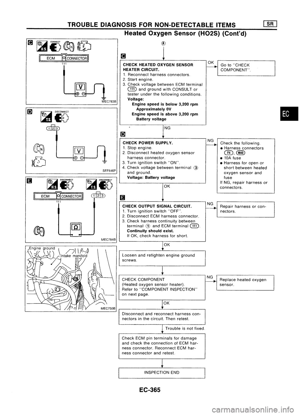
CHECK
HEATED OXYGEN SENSOR
HEATER CIRCUIT.
1. Reconnect harnessconnectors.
2. Start engine.
3. Check voltage between ECMterminal
Gill
andground withCONSULT or
tester underthefollowing conditions.
Voltage: Engine speedisbelow 3,200rpm
Approximately OV
Engine speedisabove 3,200rpm
Battery voltage
CHECK POWER SUPPLY.
1. Stop engine.
2. Disconnect heatedoxygen sensor
harness connector.
3. Turn ignition switch"ON".
4. Check voltage between terminal
@
and ground.
Voltage: Batteryvoltage@
CHECK OUTPUT SIGNALCIRCUIT.
1. Turn ignition switch"OFF".
2. Disconnect ECMharness connector.
3. Check harness continuity between
terminal
G)
and ECM terminal
Gill.
Continuity shouldexist.
If
OK, check harness forshort.
SEF646P
MEC784B
~i5
cillID
MEC783B
~i5
ECM
J9"
CONNECTOR
II
111
@J
~i)~ID
II
ECM
J9"
CONNECTOR
II
111
OK
Loosen andretighten engineground
screws.
CHECK COMPONENT
(Heated oxygensensorheater).
Refer to"COMPONENT INSPECTION"
on next page.
OK
Disconnect andreconnect harnesscon-
nectors inthe circuit. Thenretest.
NG
Replace heatedoxygen
sensor.
Trouble isnot fixed
Check ECMpinterminals fordamage
and check theconnection ofECM har-
ness connector. ReconnectECMhar-
ness connector andretest.
INSPECTION END
EC-365
Page 1085 of 1701
TROUBLEDIAGNOSIS FORNON-DETECTABLE ITEMS[][]
Heated Oxygen Sensor(H02S)(Cont'd)
COMPONENT INSPECTION
Heated oxygen sensorheater
Check resistance betweenterminals
CD
and
CID.
Resistance:
3.3•6.30
[at
25°C (77°F)]
If NG, replace theheated oxygen sensor.
AEC745
EC-366