Page 1 of 1701

AUTOMATICTRANSAXLE
SECTION
AT
CONTENTS
PREPARATION ANDPRECAUTIONS
3
Special Service Tools 3
Commercial ServiceTools 6
Service Notice 7
Supplemental RestraintSystem(SRS)"AIR
BAG" (DualAirBag System) 7
Supplemental RestraintSystem(SRS)"AIR
BAG" (Single AirBag System) 7
DESCRIPTION
8
Cross-sectional View 8
Hydraulic ControlCircuit 10
Shift Mechanism 14
Control System 15
TROUBLE DIAGNOSES 17
Preliminary Check(PriortoRoad Testing) 17
Road Testing 17
Stall Tasting 24
Pressure Testing 26
Wiring Diagram -AT - 28
Electrical Components Inspection 30
ON-VEHICLE SERVICE 31
Control ValveAssembly andAccumulator 31
Throttle WireAdjustment.. 33
Control CableInstallation andAdjustment 35
Governor Valve 36
Inhibitor SwitchAdjustment 37
Differential SideOilSeal Replacement.. 37
REMOVAL ANDINSTALLATION
39
Removal 39
Installation .40MAJOR
OVERHAUL.. 42
All Models 42
Except Model34X81 .44
Model 34X81 45•
Shift Control Components 46
i
Oil Channel 47
Locations ofAdjusting Shims,Needle
Bearings, ThrustWashers andSnap Rings -
Except Model34X81 .48
Locations ofAdjusting Shims,Needle
Bearings, ThrustWashers andSnap Rings -
Model 34X81 .49
DiSASSEMBLy 50
REPAIR FORCOMPONENT PARTS 66
Manual ShaftandThrottle Lever 66
Oil Pump 70
Control ValveAssembly 74
Control ValveUpper Body 86
Control ValveLower Body 90
Reverse Clutch 93
High Clutch 97
Forward ClutchandOverrun Clutch 102
Low &Reverse Brake 108
Rear Internal Gear,Forward ClutchHuband
Overrun ClutchHub 112
Output Shaft,Output Gear,IdlerGear,
Reduction PinionGearandBearing Retainer
- Except Model34X81 116
Output Shaft,IdlerGear, Reduction Pinion
Gear andBearing Retainer -Model 34X81 121
Band Servo Piston Assembly 126
Final Drive -Except Model34X81 131
Final Drive -Model 34X81 135
Page 8 of 1701
EXCEPTMODEL34X81
Reverse clutchdrum
DESCRIPTION
Cross-sectional View
Band servo piston
High clutch
Brake band
AT-8
Converter
housing
Torqueconverter
SAT502HB
Page 9 of 1701
MODEL34X81 DESCRIPTION
Cross-sectional View(Cant' d)
Reverse clutchdrum Band
servo piston
High clutch
Front planetary gear
Reduction piniongear
Low
&
reverse brake
Idler gear
Forward one-way clutch Low
one-way clutch
Rear planetary gear
Forward clutch
Overrun clutch
,"'I
Reverse
clutch
Brake band
Final gear
AT-9
Oil
pump assembly
Converterhousing
Torque converter
Input shaft
c
...
-;-
I
L_
Differential case
SAT101EA
•
Page 10 of 1701
MODEL34X68
4th
speed cut
valve
Overrunclutch
control
valve
Lock-up
control
valve
Torque '~..•.•
converter
>..•.••••
relief ..••.....
valve ..
Governor
valve
X:Drain port
: Orifice DESCRIPTION
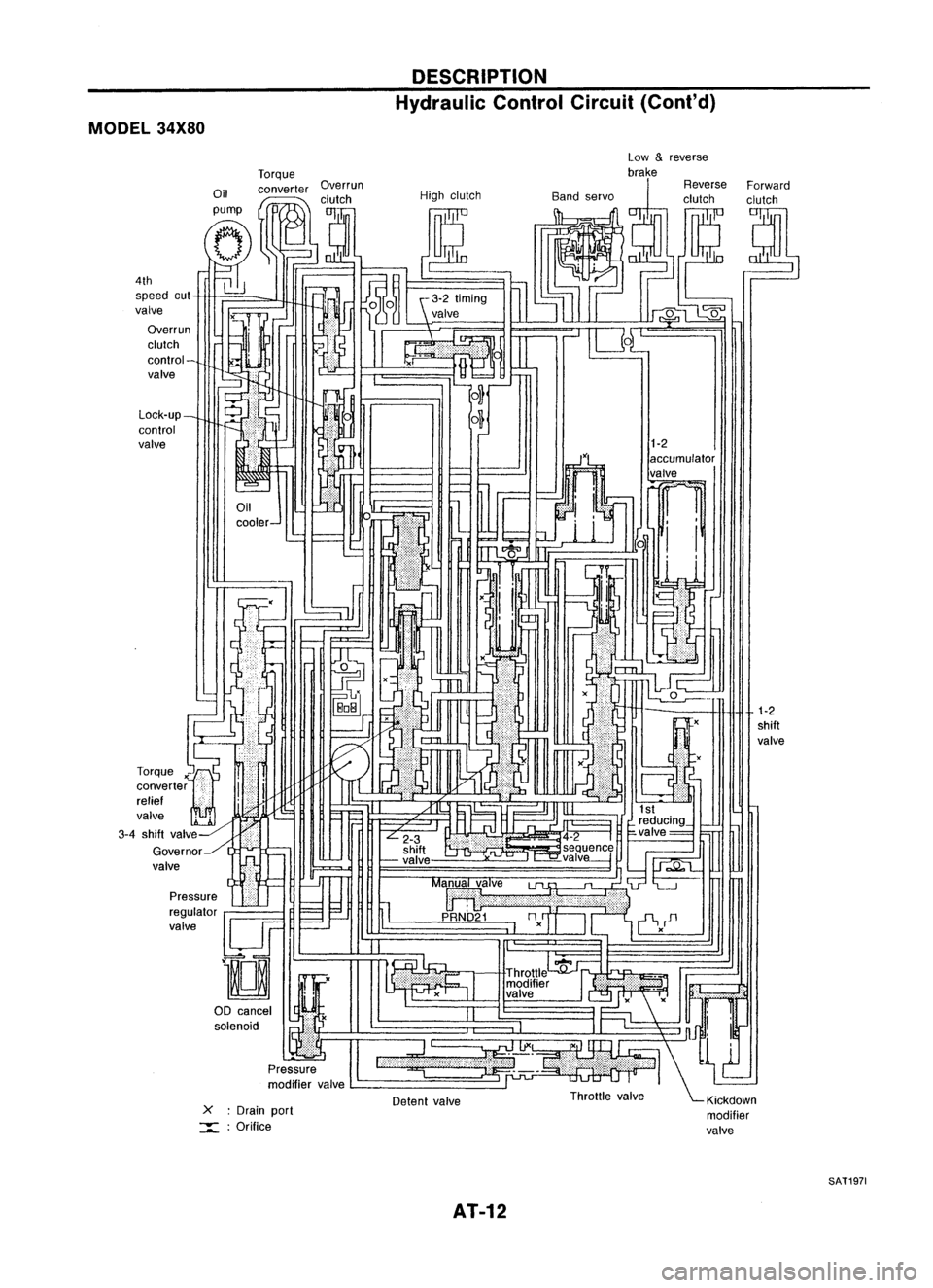
Hydraulic ControlCircuit
Low
&
reverse
brake
High clutch
Detent valve
AT-10 Forward
clutch
1-2
shift
valve
SAT1961
Page 12 of 1701

DESCRIPTION
Hydraulic ControlCircuit(Cont'd)
MODEL 34X80
1-2
shift
valve
1-2
accumulator
valve
~ 1
i i
xU
::l.
x
-
Detent valve
L-
_
-
cooler- Low
&
reverse
Torque brake
Oil converter Overrun ReverseForward
I
,clutch Highclutch Bandservo clutchclutch
pump
I
tJ
(Jp::-
(T,
tf1
--;::;-;r.]O~
~J
1~
g~ (~ ~~
l]
J~ ~
~iJ -
N
~%~
UL"-'
IU4~1~~
C-1
-!
~frEJ!
1
6 ~, -~
m
~,--J
0
- ILJ
,-O...J
r
ar
r::r=< I'---,
II .(
I'
IJ
,'-
~
,,'
(
-
I -
=-
~tL ',
~H
I~
~ ~M~ ·
F=
f='l .,.11
1-
~I" ~
" ~r'
I
L...---...l
reducing_
L
2-3 .4-2
I
~valve= ~
shift ~seq!!.enc~
~ -valve ,-=-valve---j
h
1J;;;.Q"t....
=--=-.J
II
Ma~alve
lJl.
"~'L--.J
:;;; ~I 11
p
URNb'21
nn
=-.--'
I~
II
'i-V
D
I I -,
." c:
I
Throttle
':fj'~1 .
modifier
If.'
valve .
II
I
1"
";'Jnn!
l...,
:=~-' \~
Throttle valve ~Klckdown
modifier
valve
X
:Drain port
:::::: :Orifice
Pressure
regulator
valve
!lJF
D
00 cancel
I
~Y&
solenoid •
Pressure
modifier valve
Lock-up_
control
valve
4th
speed cut
valve
Overrun
clutch
control-
valve
-=~
I
r
rr=-
LL:
J~
L~
Torque
x'"~
converter
i
i
relief '
valve
2~ '-
3-4 shift valv~-HiliJI
Governor../l ..-
valve
SAT1971
AT-12
Page 14 of 1701

DESCRIPTION
Shift Mechanism
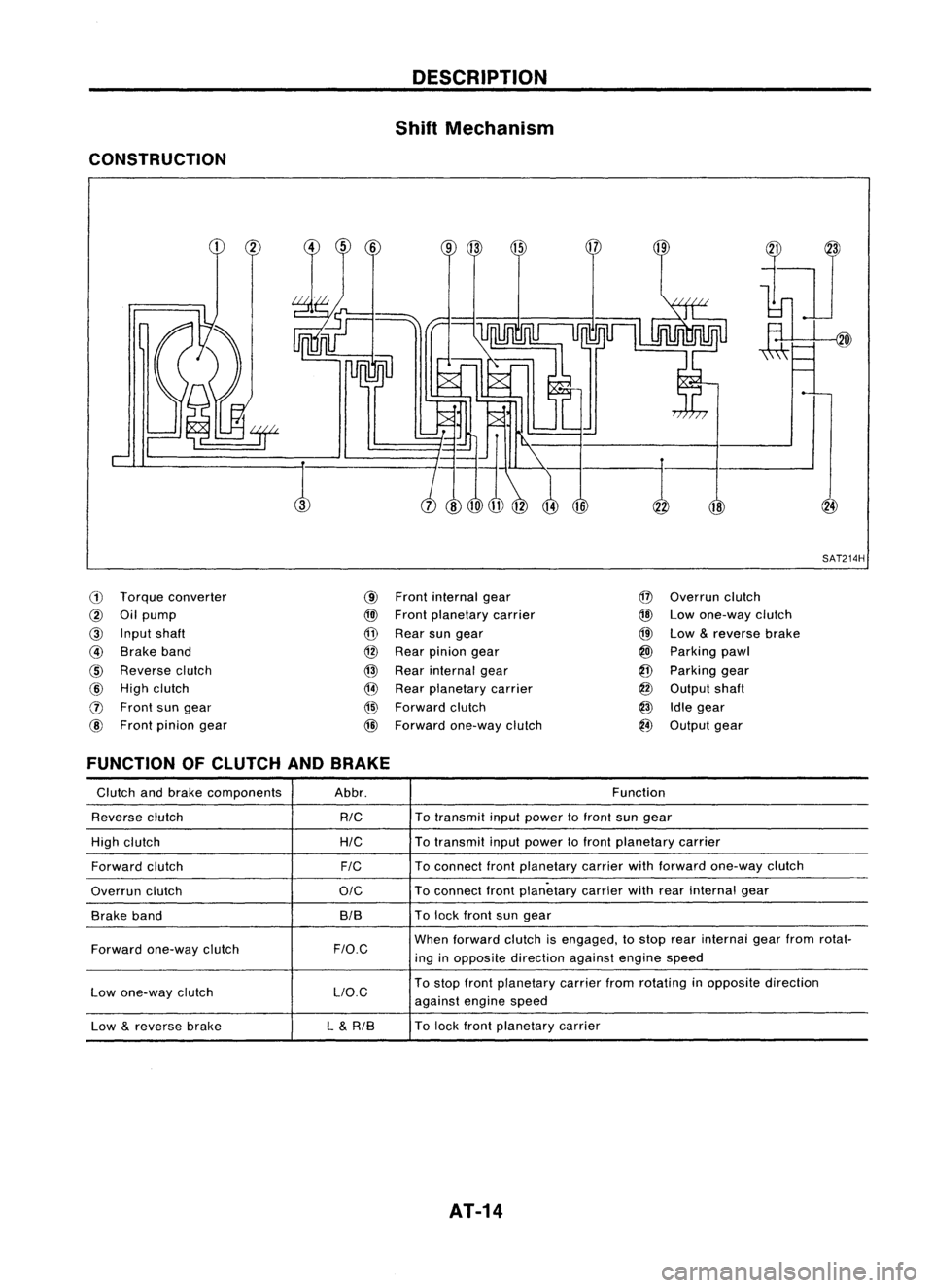
CONSTRUCTION
18
,:-1
SAT214H
ill
Torque converter
@
Oilpump
@
Input shaft
@
Brake band
@
Reverse clutch
@
High clutch
o
Front sungear
@
Front pinion gear
@
Front internal gear
@l
Front planetary carrier
@
Rear sungear
@
Rear pinion gear
@
Rear internal gear
@
Rear planetary carrier
@
Forward clutch
@
Forward one-way clutch
@
Overrun clutch
@
Lowone-way clutch
@
Low
&
reverse brake
@
Parking pawl
@
Parking gear
@
Output shaft
@
Idlegear
@
Output gear
FUNCTION OFCLUTCH ANDBRAKE
Glutch andbrake components Abbr. Function
Reverse clutch
RIG
To
transmit inputpower tofront sungear
High clutch
HIG
To
transmit inputpower tofront planetary carrier
Forward clutch
FIG
To
connect frontplanetary carrierwithforward one-way clutch
Overrun clutch
OIG
To
connect frontplanetary carrierwithrearinternal gear
Brake band BIBTo
lock front sungear
Forward one-way clutch
F/O.G
When
forward clutchisengaged, tostop rearinternai gearfrom rotat-
ing inopposite direction againstenginespeed
Low one-way clutch LlO.GTo
stop front planetary carrierfromrotating inopposite direction
against enginespeed
Low
&
reverse brake L
&
RIB To
lock front planetary carrier
AT-14
Page 15 of 1701

DESCRIPTION
Shift Mechanism (Cont'd)
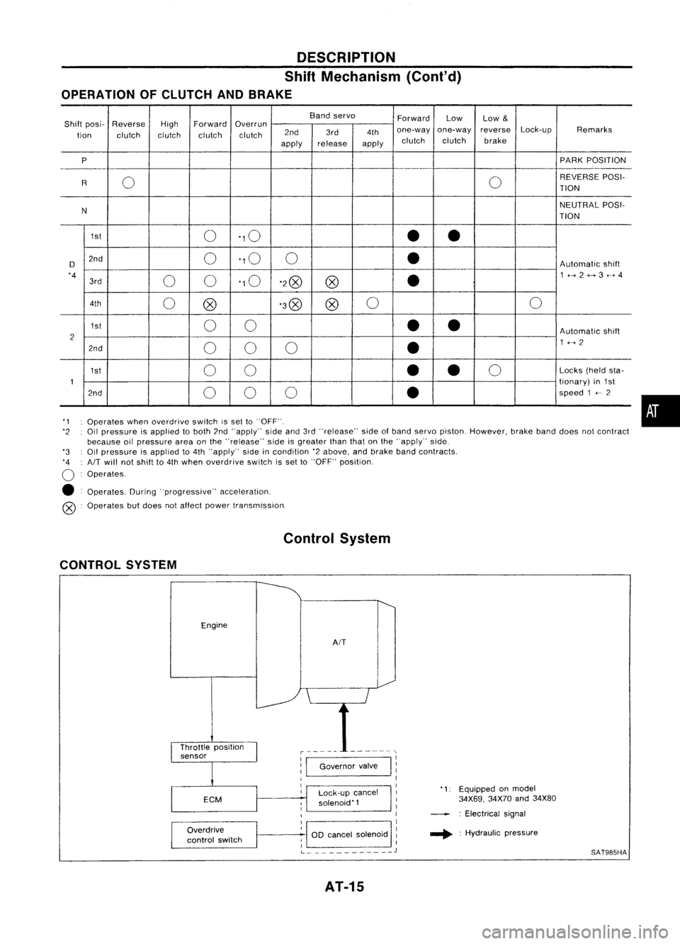
OPERATION OFCLUTCH ANDBRAKE
Bandservo
ForwardLow
Low
&
Shift posi- Reverse
HighForward
Overrun
Lock-upRemarks
tion clutch clutchclutchclutch 2nd
3rd4thone-way
one-way reverse
apply release
applyclutch
clutch brake
P PARK
POSITION
0 0REVERSE
POSI-
R TION
N NEUTRAL
POSI-
TION
1st 0'10
••
D 2nd
0'10
0
•
Automatic
shift
'4 00'10
'2@
@
•
1<-->2<-->3<-->4
3rd
4th 0@ '3@
@0
0
1st 00
••
Automatic
shift
2 1<-->2
2nd 00 0
•
1st 00
•
•
0
Locks
(heldsta-
1 tionary)
in1st
2nd 00 0
•
speed
1
<--
2
'1 Operates whenoverdrive switchissel to"OFF".
'2 Oilpressure isapplied toboth 2nd"apply" sideand3rd"release" sideofband servo piston. However, brakebanddoes notcontract
because oilpressure areaonthe "release" sideisgreater thanthatonthe "apply" side.
'3 Oilpressure isapplied to4th "apply" sideincondition '2above, andbrake bandcontracts.
'4 AIT
will notshift to4th when overdrive switchisset to"OFF" position.
o
Operates.
• Operates. During"progressive" acceleration.
@ Operates butdoes notaffect power transmission.
Control System
CONTROL SYSTEM
Engine
AIT
•
Lock-up cancel
solenoid'1
Overdrive
control switch
1:1
Governor valve
I
11
1
I
1
1
OD cancel solenoid :
; I
L
J
AT-15
'1:
Equipped onmodel
34X69, 34X70and34X80
: Electrical signal
.... :Hydraulic pressure
SAT985HA
Page 17 of 1701

Fluidleakage TROUBLE
DIAGNOSES
Preliminary Check(PriortoRoad Testing)
AIT FLUID CHECK
Fluid leakage check
1. Clean areasuspected ofleaking, -for example, mating
surface ofconverter housingandtransmission case.
2. Start engine, applyfootbrake, placeselector leverin"0"
position andwait afew minutes.
3. Stop engine.
4. Check forfresh leakage.
SAT288G
Fluidcondition check
Fluid levelcheck -Refer toMA section (CHASSIS AND
BODY MAINTENANCE).
Fluid
color
Oark orblack withburned odor
Milky pink
Varnished fluid,lighttodark brown
and tacky Suspected
problem
Wear offrictional material
Water contamination
- Road water entering through
filler tubeorbreather
Oxidation
- Over orunder filling
- Overheating
•
Road Testing
Perform roadtests using "Symptom" chart.Refertopage
AT-20.
"P"
POSITION
1. Place selector leverin"P" position andstart engine. Stop
engine andrepeat theprocedure inall positions, including
neutral position.
2. Stop vehicle onaslight upgrade andplace selector leverin
"P" position. Releaseparkingbraketomake surevehicle
remains locked.
"R"
POSITION
1. Manually moveselector leverfrom"P"to"R", andnote
shift quality.
2. Drive vehicle inreverse longenough todetect slippage or
other abnormalities.
"N"
POSITION
1. Manually moveselector leverfrom"R"and"0"to"N" and
note shift quality.
2. Release parkingbrakewithselector leverin"N" position.
Lightly depress accelerator pedaltomake surevehicle
does notmove. (When vehicle isnew orsoon afterclutches
have been replaced, vehiclemaymove slightly. Thisisnot
a problem.)
AT-17