Page 279 of 1701

CONTROLVALVE
Proportioning Valve
INSPECTION
CAUTION:
• Carefully monitorbrakefluidlevel atmaster cylinder.
• Use new brake fluid"DOT 3"or"DOT 4".
• Donot mix different typesofbrake fluids(DOT3,DOT 4).
• Becareful nottosplash brakefluidonpainted areas;itmay
cause paintdamage. Ifbrake fluidissplashed onpaint
areas, washitaway withwater immediately.
• Depress pedalslowly whenraising frontbrake pressure.
• Check rearbrake pressure 2seconds afterfront brake pres-
sure reaches specified value.
• For models withABS disconnect harnessconnectors from
ABS actuator relaybefore checking.
1.
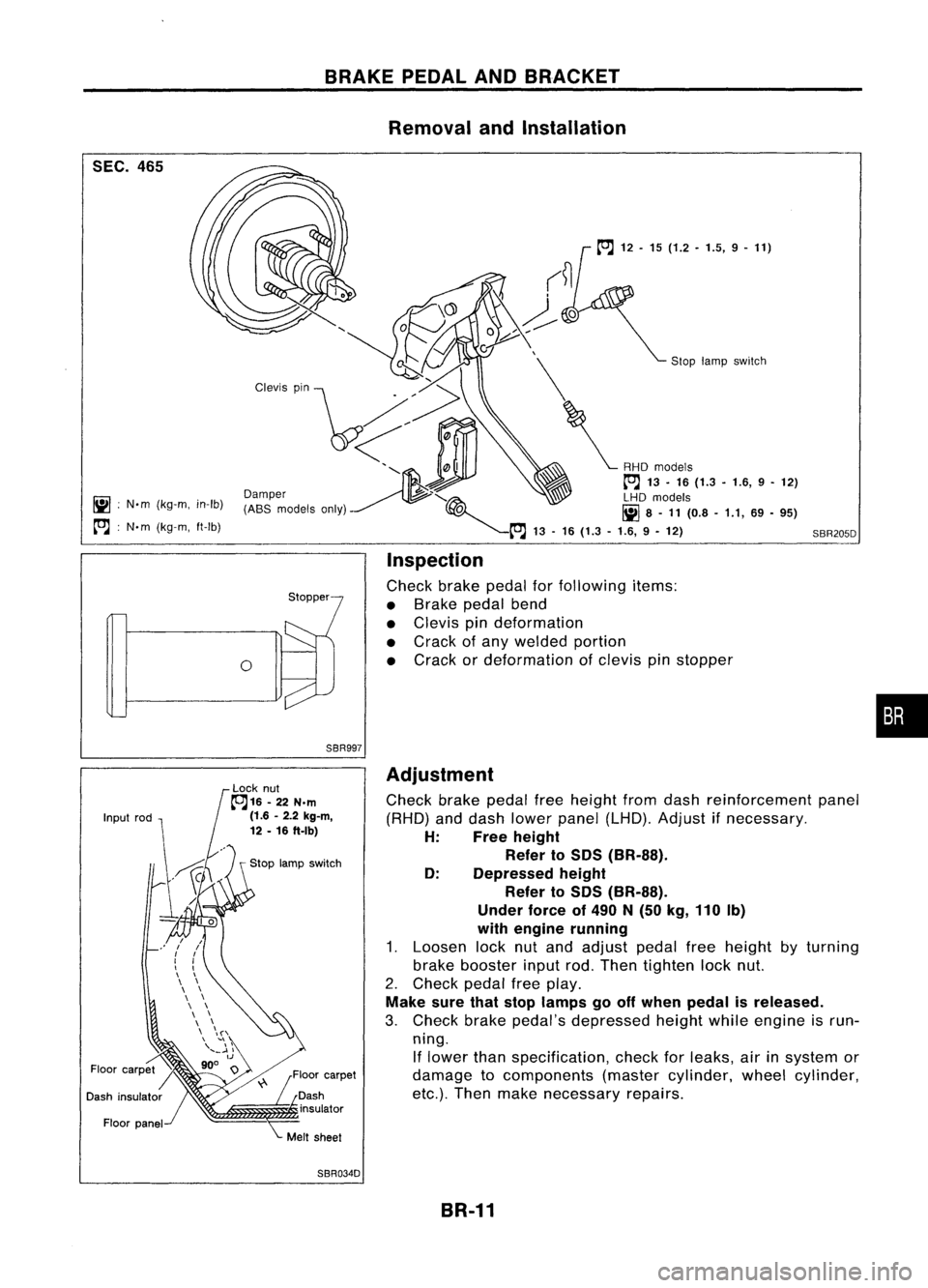
Connect Tooltoair bleeders offront andrear brakes on
either
LH
or
RH
side.
2. Bleed airfrom theTool.
3. Check rearbrake pressure bydepressing brakepedal
(increasing frontbrake pressure).
Unit:kPa(bar, kg/cm
2,
psi)
Without ABS
I
With
ABS
Applied models
GA14DE,GA16DE,CD20 GA16DE'
SR20DE
Applied pressure 7.3556.375
5,394
(Front brake) (73.6,
75,1,067) (63.7,65,924)
(53.9,55,782)
3,432 -3,825 2,452-2,844
Output pressure 5,100
-5,492 (34.3-38.2, (245-28.4,
(Rear brake) (51.0
-54.9, 52-56, 739 -796) 35-39, 25-29,
498 -555) 356-412)
*
Models forAustralia
If
output pressure isout ofspecifications, replacedualpro- •••
portioning valve(separated type)ormaster cylinder assem-
bly (built-in type).
4. Bleed airafter disconnecting theTool. Refer to"Bleeding
Procedure", BR-5.
BR-9
Page 280 of 1701
CONTROLVALVE
Proportioning Valve(Cont'd)
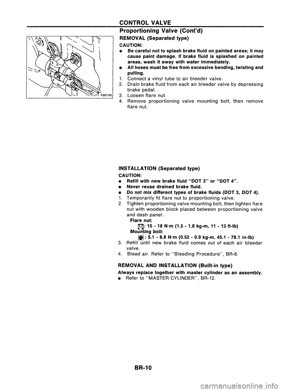
REMOVAL (Separated type)
CAUTION:
• Becareful nottosplash brakefluidonpainted areas;itmay
cause paintdamage. Ifbrake fluidissplashed onpainted
areas, washitaway withwater immediately.
• Allhoses mustbefree from excessive bending,twistingand
pulling.
1. Connect avinyl tubetoair bleeder valve.
2. Drain brake fluidfrom each airbleeder valvebydepressing
brake pedal.
3. Loosen flarenut.
4. Remove proportioning valvemounting bolt,then remove
flare nut.
INSTAllATION (Separatedtype)
CAUTION:
• Refill withnewbrake fluid"DOT 3"or"DOT 4".
• Never reusedrained brakefluid.
• Donot mix different typesofbrake fluids(DOT3,DOT 4).
1. Temporarily fitflare nuttoproportioning valve.
2. Tighten proportioning valvemounting bolt,then tighten flare
nut with wooden blockplaced between proportioning valve
and dash panel.
Flare nut:
tDJ:
15-18 N'm (1.5-1.8 kg-m, 11-13 ft-Ib)
Mounting bolt:
11]:
5.1-8.8 N'm (0.52 -0.9 kg-m, 45.1-78.1 in-Ib)
3. Refill untilnewbrake fluidcomes outofeach airbleeder
valve.
4. Bleed air.Refer to"Bleeding Procedure", BR-6.
REMOVAL ANDINSTAllATION (Built-intype)
Always replace together withmaster cylinder asan assembly.
• Refer to"MASTER CYLINDER", BR-12.
BR-10
Page 281 of 1701
SEC.465
iii :
N'm (kg-m, in-Ib)
~ :N'm (kg-m, ft-Ib)
BRAKE
PEDALANDBRACKET
Removal andInstallation
Sloplamp sWitch
SBR205D
o
Inspection
Check brakepedalforfollowing items:
• Brake pedalbend
• Clevis pindeformation
• Crack ofany welded portion
• Crack ordeformation ofclevis pinstopper
•
SBR997
Adjustment
Check brakepedalfreeheight fromdash reinforcement panel
(RHD) anddash lower panel (LHD). Adjust ifnecessary.
H: Freeheight
Refer to
50S
(BR-SS).
0: Depressed height
Refer to
50S
(BR-SS).
Under forceof
490
N
(50
kg,
110
Ib)
with engine running
1. Loosen locknutand adjust pedalfreeheight byturning
brake booster inputrod.Then tighten locknut.
2. Check pedalfreeplay.
Make surethatstop lamps gooff when pedal isreleased.
3. Check brakepedal's depressed heightwhileengine isrun-
ning. If lower thanspecification, checkforleaks, airinsystem or
damage tocomponents (mastercylinder, wheelcylinder,
etc.). Then make necessary repairs.
SBR034D BR-11
Page 282 of 1701
MASTERCYLINDER
Removal
CAUTION:
• Becareful nottosplash brakefluidonpainted areas;itmay
cause paintdamage. Ifbrake fluidissplashed onpainted
areas, washitaway withwater immediately.
• Inthe case ofbrake fluidleakage fromthemaster cylinder,
disassemble thecylinder. Thencheck piston cupsfordefor-
mation orscratches andreplace necessary parts.
1. Connect avinyl tubetoair bleeder valve.
2. Drain brake fluidfrom each airbleeder valve,depressing
brake pedaltoempty fluidfrom master cylinder.
3. Remove brakepipeflare nuts.
4. Remove mastercylinder mounting nuts.
Models withASS
/O-ring~
'V
(ModelswithABS only)
'\~ /'Valve stopper
T@" ~
1.5.2.9
(0.15.0.3, 13.0•26.0)
o
l-~
~ 11.7 -14.7 \
(1.2 -1.5, 8.7-10.8)
SBR019DB
Seal~
___
Reservoir tank
jJ'JD~----
~ ..-:'J
C'9 ---
Secondarypiston
Stopper cap~assembly
~f]
Cylinder
body
N.m (kg-m, in-Ib)
N.m (kg-m. ft-Ib)
Brake fluidpoint
Reservoir
cap
----g
Oil strainer ----. ~
L------- -
SEC.
460
Disassembly
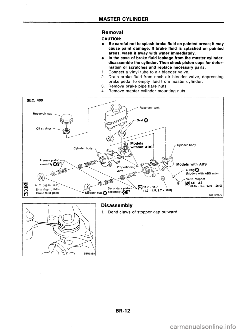
1. Bend claws ofstopper capoutward.
BR-12
Page 284 of 1701
SBR435BMASTER
CYLINDER
Assembly (Cont'd)
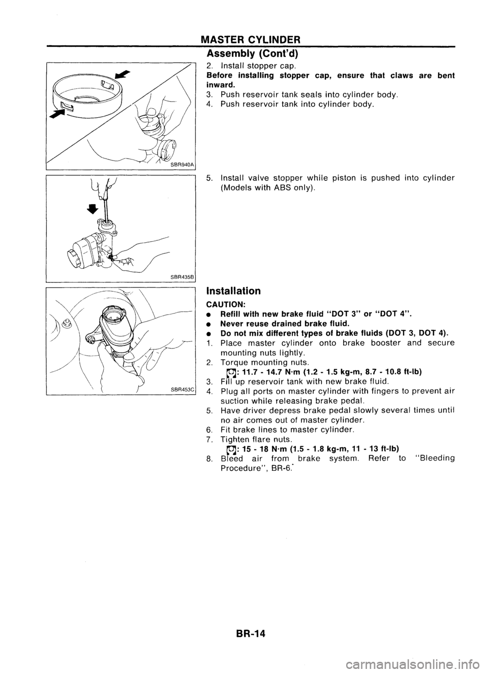
2. Install stopper cap.
Before installing stoppercap,ensure thatclaws arebent
inward.
3. Push reservoir tankseals intocylinder body.
4. Push reservoir tankintocylinder body.
5. Install valvestopper whilepiston ispushed intocylinder
(Models withABS only).
Installation
CAUTION:
• Refill withnewbrake fluid"DOT 3"or"DOT 4".
• Never reusedrained brakefluid.
• Donot mix different typesofbrake fluids(DOT3,DOT 4).
1. Place master cylinder ontobrake booster andsecure
mounting nutslightly.
2. Torque mounting nuts.
~: 11.7 -14.7 N'm(1.2-1.5 kg-m, 8.7-10.8 ft-Ib)
3. Fillupreservoir tankwith newbrake fluid.
4. Plug allports onmaster cylinder withfingers toprevent air
suction whilereleasing brakepedal.
5. Have driver depress brakepedalslowly several timesuntil
no air comes outofmaster cylinder.
6. Fitbrake linestomaster cylinder.
7. Tighten flarenuts.
~: 15-18 N'm (1.5-1.8 kg-m, 11-13 ft-Ib)
8. Bleed airfrom brake system. Referto"Bleeding
Procedure", BR-6."
BR-14
Page 285 of 1701
OKNGBRAKE
BOOSTER
On-vehicle Service
OPERATING CHECK
• Depress brakepedalseveral timeswithengine off.After
exhausting vacuum,makesurethere isno change inpedal
stroke.
• Depress brakepedal, thenstart engine. Ifpedal goesdown
slightly, operation isnormal.
AIRTIGHT CHECK
• Start engine, andstop itafter oneortwo minutes. Depress
SBR002A
brakepedalseveral timesslowly. Booster isairtight ifpedal
stroke isless each time.
• Depress brakepedalwhileengine isrunning, andstop
engine withpedal depressed. Thepedal stroke should not
change afterholding pedaldownfor
30seconds.
SBR365AA Removal
CAUTION:
• Becareful nottosplash brakefluidonpainted areas;itmay
cause paintdamage. Ifbrake fluidissplashed onpainted
areas, washitaway withwater immediately.
• Be careful nottodeform orbend brake pipes, during
removal ofbooster.
SEC.
465.470
BR-15Gasket
~ :N.m (kg-m. ft-Ib)
SBR223BB
•
Page 286 of 1701
Approx.125mm (4.92 In) BRAKE
BOOSTER
Inspection
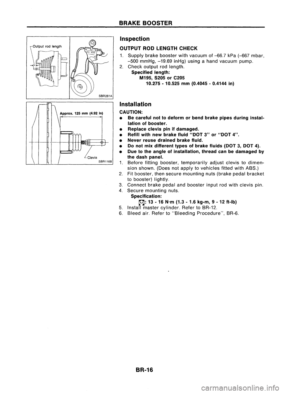
OUTPUT RODLENGTH CHECK
1. Supply brakebooster withvacuum of-66.7 kPa(-667 mbar,
-500 mmHg, -19.69inHg)usingahand vacuum pump.
2. Check output rodlength.
Specified length:
M195, S205orC205
10.275 -10.525 mm(0.4045 -0.4144 in)
Installation
CAUTION: • Becareful nottodeform orbend brake pipesduring instal-
lation ofbooster.
• Replace clevispinifdamaged.
• Refill withnewbrake fluid"DOT 3"or"DOT 4".
• Never reusedrained brakefluid.
• Donol mix different typesofbrake fluids(DOT3,DOT 4).
• Due tothe angle ofinstallation, threadcanbedamaged by
the dash panel.
1. Before fittingbooster, temporarily adjustclevistodimen-
sion shown. (Doesnotapply tovehicles fittedwithABS.)
2. Fitbooster, thensecure mounting nuts(brake pedalbracket
to booster) lightly.
3. Connect brakepedalandbooster inputrodwith clevis pin.
4. Secure mounting nuts.
Specification:
~: 13-16 N'm (1.3-1.6 kg-m, 9-12 ft-Ib)
5. Install master cylinder. RefertoBR-12.
6. Bleed air.Refer to"Bleeding Procedure", BR-6.
BR-16
Page 287 of 1701
SBR225B
----a
MoreIh.. 24mm
(0.94 In)
----------r:~
---------~~~----------
Connect hoseuntilitcontacts
protrusion onvacuum tube.
VACUUM
HOSE
Removal andInstallation
CAUTION:
When installing vacuumhoses,payattention tothe following
points.
• Donot apply anyoilorlubricants tovacuum hoseandcheck
valve.
• Insert vacuum tubeintovacuum hoseasshown.
• Install checkvalve, paying attention toits direction.
TYPE 1
Intake manifold Brakebooster
; C::::::::'::::~:d
q
SBR498A
CAUTION
~
... ENG. TYPE
2
Inspection
HOSES ANDCONNECTORS
Check vacuum lines,connections andcheck valvefor
airtightness, improperattachment, chafinganddeterioration.
BR-17
•