1995 NISSAN ALMERA N15 brake
[x] Cancel search: brakePage 168 of 1701
SERVICEDATAANDSPECIFICATIONS (SOS)
Specifications andAdjustments (Cont'd)
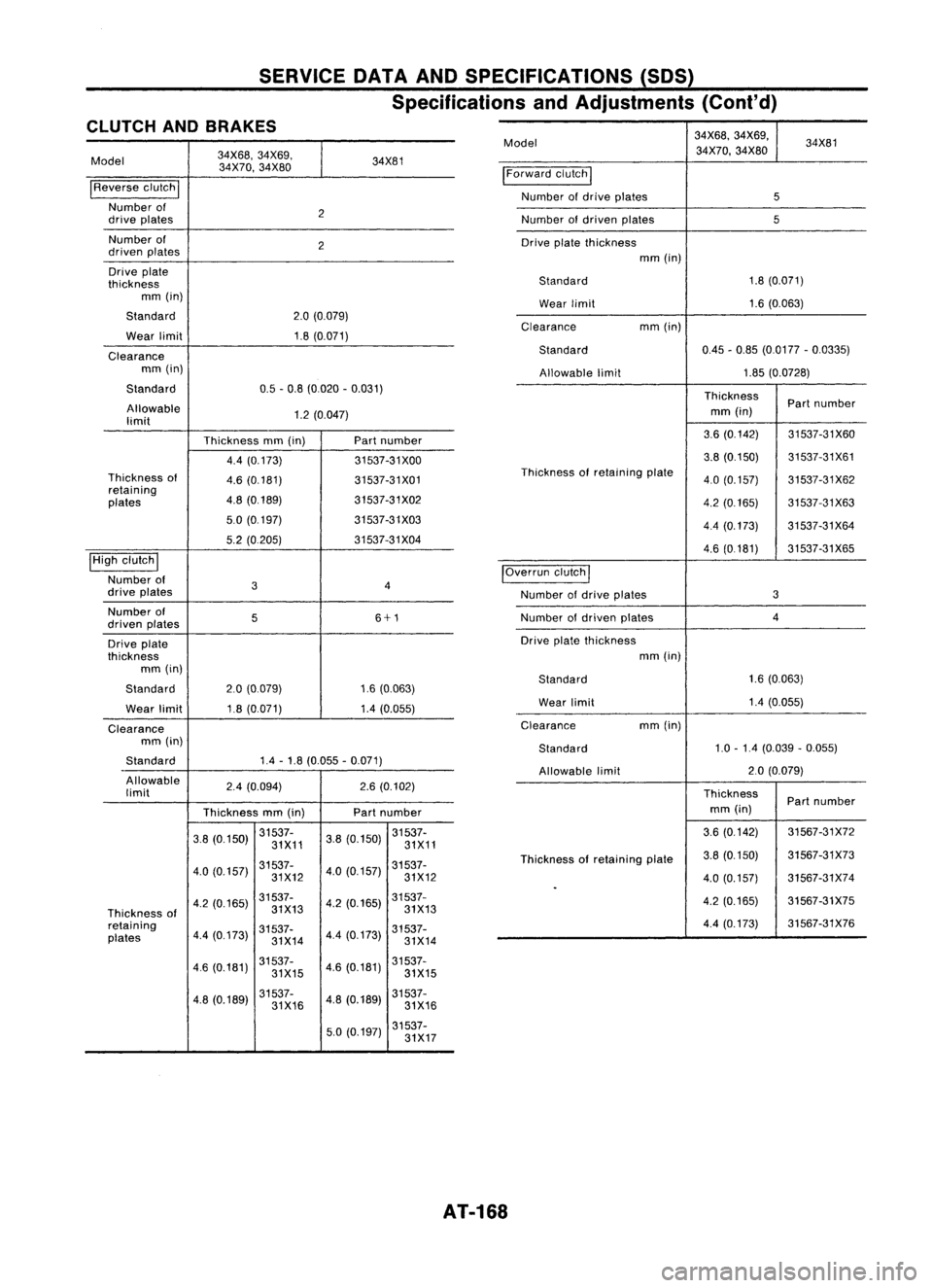
CLUTCH ANDBRAKES
Model
34X68,
34X69,
34X81
34X70, 34X80
I
Reverse clutch
I
Number of
2
drive plates
Number of
2
driven plates
Drive plate
thickness mm(in)
Standard
2.0(0.079)
Wear limit
1.8(0.071)
Clearance mm(in)
Standard
0.5-0.8 (0.020 -0.031)
Allowable
1.2(0.047)
limit
Thicknessmm(in) Partnumber
4.4 (0.173) 31537-31XOO
Thickness 01
4.6(0.181) 31537-31X01
retaining
4.8(0.189) 31537-31X02
plates
5.0(0.197) 31537-31X03
5.2 (0.205) 31537-31X04
I
High clutch
I
Number 01
3 4
drive plates
Number 01
5 6+1
driven plates
Drive plate
thickness mm(in)
Standard
2.0(0.079) 1.6(0.063)
Wear limit
1.8
(0.071) 1.4(0.055)
Clearance mm(in)
Standard
1.4
-1.8 (0.055 -0.071)
-
Allowable
2.4(0.094) 2.6(0.102)
limit
Thicknessmm(in) Part
number
3.8 (0.150) 31537-
3.8(0.150) 31537-
31X11 31X11
4.0 (0.157) 31537-
4.0(0.157) 31537-
31X12 31X12
4.2 (0.165) 31537-
4.2(0.165) 31537-
Thickness 01
31X13
31X13
retaining
4.4(0.173) 31537-
4.4(0.173) 31537-
plates
31X1431X14
46 (0.181) 31537-
4.6(0.181) 31537-
31X15 31X15
4.8 (0.189) 31537-
4.8(0.189) 31537-
31X16 31X16
5.0 (0.197) 31537-
31X17
Model
34X68,
34X69,
34X81
34X70, 34X80
I
Forward clutch
I
Number ofdrive plates
5
Number ofdriven plates
5
Drive platethickness
mm(in)
Standard
1.8
(0.071)
Wear limit
1.6(0.063)
Clearance mm(in)
Standard
0.45-0.85 (0.0177 -0.0335)
Allowable limit
1.85
(0.0728)
Thickness Partnumber
mm (in)
3.6 (0.142) 31537-31X60
3.8 (0.150) 31537-31X61
Thickness ofretaining plate
4.0(0.157) 31537-31X62
4.2 (0.165) 31537-31X63
4.4 (0.173) 31537-31X64
4.6 (0.181) 31537-31X65
IOverrun clutch
I
Number ofdrive plates
3
Number ofdriven plates
4
Drive platethickness
mm(in)
Standard
1.6
(0.063)
Wear limit
1.4
(0.055)
Clearance mm
(in)
Standard
1.0
-1.4 (0.039 -0.055)
Allowable limit
2.0
(0.079)
Thickness Partnumber
mm (in)
3.6 (0.142) 31567-31X72
Thickness 01retaining plate
3.8
(0.150) 31567-31X73
4.0 (0.157) 31567-31X74
.
4.2(0.165) 31567-31X75
4.4 (0.173) 31567-31X76
AT-168
Page 169 of 1701
•
Oil
pump sideclear-
0.02-0.04 (0.0008 -0.0016)
ance mm(in)
Innergear
Thickness Partnumber
mm (in)
9.99 -10.00
31346-31XOO
(0.3933 -0.3937)
9.98 -9.99
31346-31X01
(0.3929 -0.3933)
9.97 -998
31346-31X02
Thickness ofinner
(0.3925
-0.3929)
gears andouter gears
Outergear
Thickness Partnumber
mm (in)
9.99 -10.00
31347-31XOO
(0.3933 -0.3937)
9.98 -9.99
31347-31X01
(0.3929 -0.3933)
9.97 -9,98
31347-31X02
(0.3925 -0.3929)
Clearance betweenoil
pump housing and
outer gear
mm(in)
Standard
008-0 15 (0.0031 -0.0059)
Allowable limit
015(0.0059)
Oil pump cover seal
ring clearance
mm(in)
Standard
0.10-0.25 (0.0039 -0.0098)
Allowable limit
0.25(0.0098)
SERVICE
OATAAND SPECIFICATIONS (50S)
Specifications andAdjustments (Cont'd)
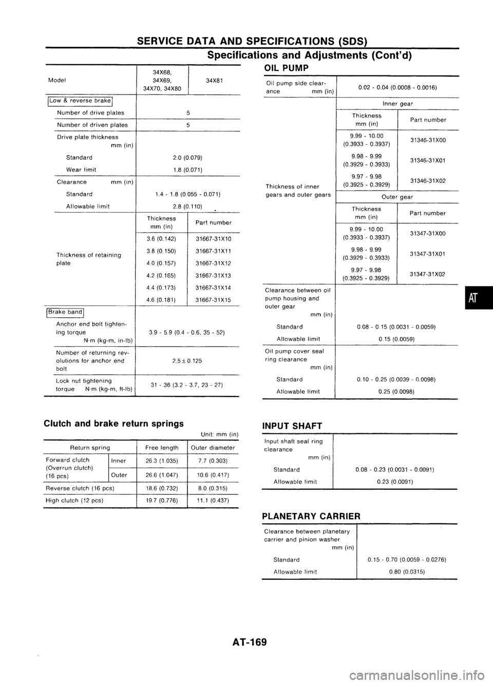
OIL PUMP
34X68,
Model
34X69,34X81
34X70, 34X80
ILow
&
reverse brake
I
Number ofdrive plates
5
Number ofdriven plates
5
Drive platethickness
mm(in)
Standard
2.0(0.079)
Wear limit
1.8(0.071)
Clearance mm(in)
Standard
1.4-1.8 (0.055 -0.071)
Allowable limit
2.8(0.110)
.
Thickness Partnumber
mm (in)
36 (0.142)
31667-31X10
Thickness ofretaining
38(0150)
31667-31X11
plate
4.0(0157)
31667-31X12
4.2 (0.165)
31667-31X13
4.4 (0.173)
31667-31X14
4.6 (0.181)
31667-31X15
I
Brake band
I
Anchor endbolttighten-
ing torque
39-5.9 (0.4 -06, 35-52)
N'm (kg-m, in-Ib)
Number ofreturning rev-
olutions foranchor end
2.5:1e0125
bolt
Lock nuttightening
31-36 (3.2 -3.7, 23-27)
torque N'm(kg-m, ft-Ib)
Clutch andbrake return springs
INPUTSHAFT
Unit: mm(in)
Return spring Freelength
Outerdiameter
Forward clutch
Inner
263(1.035) 77(0.303)
(Overrun clutch)
(16
pes) Outer
266
(1.047) 10.6(0.417)
Reverse clutch
(16
pes)
18.6(0.732) 80(0.315)
High clutch
(12
pes)
197(0.776) 11.1(0.437)
Input
shaft sealring
clearance mm(in)
Standard
Allowable limit
0.08
-0.23 (0.0031 -0.0091)
0.23 (0.0091)
PLANETARY CARRIER
Clearance betweenplanetary
carrier andpinion washer
mm(in)
Standard Allowable limit
0.15
-0.70 (0.0059 -0.0276)
080 (0.0315)
AT-169
Page 271 of 1701
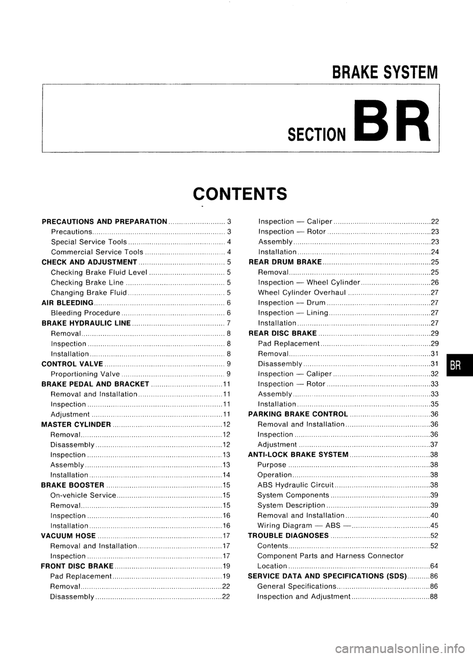
BRAKESYSTEM
SECTION
CONTENTS BR
PRECAUTIONS ANDPREPARATION
3
Precautions 3
Special Service Tools 4
Commercial ServiceTools 4
CHECK ANDADJUSTMENT 5
Checking BrakeFluidLevel 5
Checking BrakeLine 5
Changing BrakeFluid 5
AIR
BLEEDING 6
Bleeding Procedure 6
BRAKE HYDRAULIC LINE 7
Removal 8
Inspection 8
Installation 8
CONTROL VALVE 9
Proportioning Valve 9
BRAKE PEDALANDBRACKET 11
Removal andInstallation 11
Inspection 11
Adjustment 11
MASTER CYLINDER 12
Removal 12
Disassembly 12
Inspection 13
Assembly 13
Installation 14
BRAKE BOOSTER 15
On-vehicle Service 15
Removal 15
Inspection 16
Installation 16
VACUUM HOSE 17
Removal andInstallation 17
Inspection 17
FRONT DISCBRAKE 19
Pad Replacement.. 19
Removal 22
Disassembly 22Inspection
-Caliper 22
Inspection -Rotor 23
Assembly '".23
Installation 24
REAR DRUM BRAKE 25
Removal 25
Inspection -Wheel Cylinder 26
Wheel Cylinder Overhaul 27
Inspection -Drum 27
Inspection -Lining 27
Installation 27
REAR DISCBRAKE 29
Pad Replacement 29
~~s:~::~'~I~':::::::::::'::: ::.::::::::.::::::.::::::::::.::::::.::::::::~~ •••
Inspection -Caliper 32
Inspection -Rotor 33
Assembly 33
Installation 35
PARKING BRAKECONTROL 36
Removal andInstallation 36
Inspection 36
Adjustment ." 37
ANTI-LOCK BRAKESYSTEM 38
Purpose 38
Operation 38
ABS Hydraulic Circuit 38
System Components 39
System Description 39
Removal andInstallation .40
Wiring Diagram -ABS - .45
TROUBLE DIAGNOSES
52
Contents 52
Component PartsandHarness Connector
Location 64
SERVICE DATAANDSPECIFICATIONS (SDS)86
General Specifications 86
Inspection andAdjustment 88
Page 274 of 1701
GG94310000or
commercial equivalent
SBR820BA
For
tightening flarenut
Tool number
Tool name
PRECAUTIONS
ANDPREPARATION
Precautions (Conl'd)
BRAKE SYSTEM
• Recommended fluidisbrake fluid"DOT 3"or"DOT 4".
• Never reusedrained brakefluid.
• Donot mix different typesofbrake fluids (DOT3,DOT 4).
• Becareful nottosplash brakefluidonpainted areas;itmay
cause paintdamage. Ifbrake fluidissplashed onpainted
areas, washitaway withwater immediately.
• Toclean master cylinder parts,discbrake caliper partsor
wheel cylinder parts,useclean brake fluid.
• Never usemineral oilssuch asgasoline orkerosene. They
will ruin rubber partsofhydraulic system.
• Use flare nutwrench whenremoving andinstalling brake
tubes.
• Always torquebrakelineswhen installing.
WARNING:
• Clean brakes withavacuum dustcollector tominimize risk
of health hazard frompowder causedbyfriction.
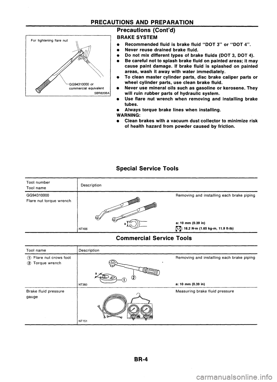
Special Service Tools
Description
GG9431 0000
Flare nuttorque wrench
NT406
Removing
andinstalling eachbrake piping
a: 10 mm (0.39 in)
~: 16.2N'm(1.65 kg-m, 11.9f1-lb)
Commercial ServiceTools
Description
Tool name
CD
Flare nutcrows foot
@ Torque wrench
Brake fluidpressure
gauge
NT360
NT151
Removing
andinstalling eachbrake piping
a: 10 mm (0.39 in)
Measuring brakefluidpressure
BR-4
Page 275 of 1701
CHECKANDADJUSTMENT
OK
MINMax.
line
Min. line
SBR418C
Checking
BrakeFluidLevel
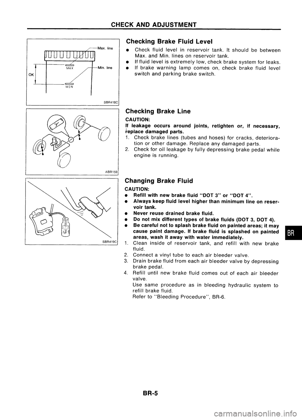
• Check fluidlevel inreservoir tank.Itshould bebetween
Max. andMin. lines onreservoir tank.
• Iffluid level isextremely low,check brakesystem forleaks.
• Ifbrake warning lampcomes on,check brakefluidlevel
switch andparking brakeswitch.
ABR159
SBR419C
Checking
BrakeLine
CAUTION: If leakage occursaround joints,retighten or,ifnecessary,
replace damaged parts.
1. Check brakelines(tubes andhoses) forcracks, deteriora-
tion orother damage. Replaceanydamaged parts.
2. Check foroilleakage byfully depressing brakepedalwhile
engine isrunning.
Changing BrakeFluid
CAUTION:
• Refill withnewbrake fluid"DOT 3"or"DOT 4".
• Always keepfluidlevel higher thanminimum lineonreser-
voir tank.
• Never reusedrained brakefluid.
• Donot mix different typesofbrake fluids(DOT3,DOT 4).
• Becareful nottosplash brakefluidonpainted areas;itmay •
cause paintdamage. Ifbrake fluidissplashed onpainted :•
areas, washitaway withwater immediately.
1. Clean inside ofreservoir tank,andrefill withnewbrake
fluid.
2. Connect avinyl tubetoeach airbleeder valve.
3. Drain brake fluidfrom each airbleeder valvebydepressing
brake pedal.
4. Refill untilnewbrake fluidcomes outofeach airbleeder
valve.
Use same procedure asinbleeding hydraulic systemto
refill brake fluid.
Refer to"Bleeding Procedure", BR-6.
BR-5
Page 276 of 1701
SBR995
SBR419C AIR
BLEEDING
Bleeding Procedure
CAUTION:
• Carefully monitorbrakefluidlevel atmaster cylinder during
bleeding operation.
• Ifmaster cylinder issuspected tohave airinside, bleedair
from master cylinder first.Refer to"Installation", "MASTER
CYLINDER", BR-12.
• Fill reservoir withnewbrake fluid"DOT 3"or"DOT
4".
Make sureitis full atall times whilebleeding airout of
system.
• Donot mix different typesofbrake fluids(DOT3,DOT 4).
• Place acontainer undermaster cylinder toavoid spillage of
brake fluid.
• For models withABS, turnignition switchOFFanddiscon-
nect ABS actuator connector orbattery cable.
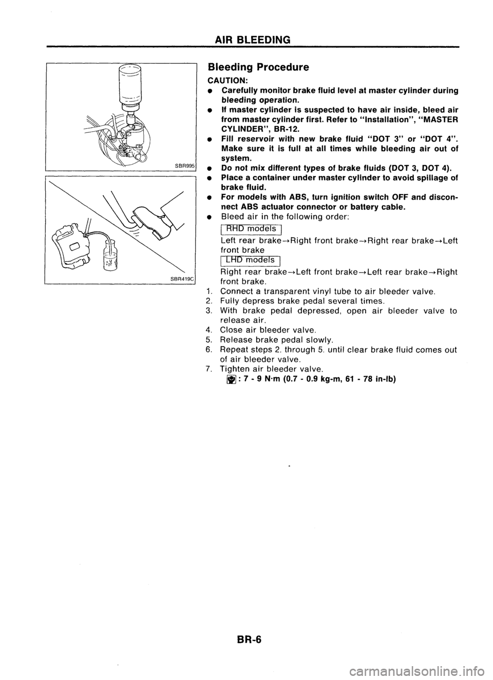
• Bleed airinthe following order:
I
RHO models
I
Left rear brake-+Right frontbrake-+Right rearbrake-+Left
front brake
I
LAD models
I
Right rearbrake-+Left frontbrake-+Left rearbrake-+Right
front brake.
1. Connect atransparent vinyltubetoair bleeder valve.
2. Fully depress brakepedalseveral times.
3. With brake pedaldepressed, openairbleeder valveto
release air.
4. Close airbleeder valve.
5. Release brakepedalslowly.
6. Repeat steps2.through 5.until clear brake fluidcomes out
of air bleeder valve.
7. Tighten airbleeder valve.
~: 7-
9 N.m (0.7-0.9 kg-m, 61-78 in-Ib)
BR-6
Page 277 of 1701
BRAKEHYDRAULIC LINE
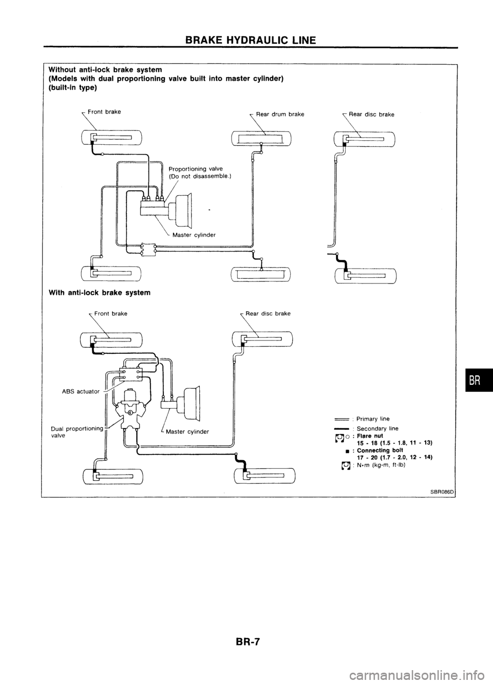
Without anti-lock brakesystem
(Models withdual proportioning valvebuiltintomaster cylinder)
(built-in type)
Proportioningvalve
(Do notdisassemble.)
With anti-lock brakesystem
ASS actuator
L
Master cylinder
=
.
Primary line
- .Secondary line
~ 0:Flare nut
15 -18 (1.5 -1.8, 11-13)
• :Connecting bolt
17 -20 (1.7 -2.0, 12-14)
~ :N.m (kg-m. ft-Ib)
SBR086D
•
BR-7
Page 278 of 1701
BRAKEHYDRAULIC LINE
SBR419C
For tightening flarenut
~GG94310000
or
commercial equivalent
SBR820BA
Removal
CAUTION: • Becareful nottosplash brakefluidonpainted areas;itmay
cause paintdamage. Ifbrake fluidissplashed onpainted
areas, washitaway withwater immediately.
• Allhoses mustbefree from excessive bending,tWistingand
pulling.
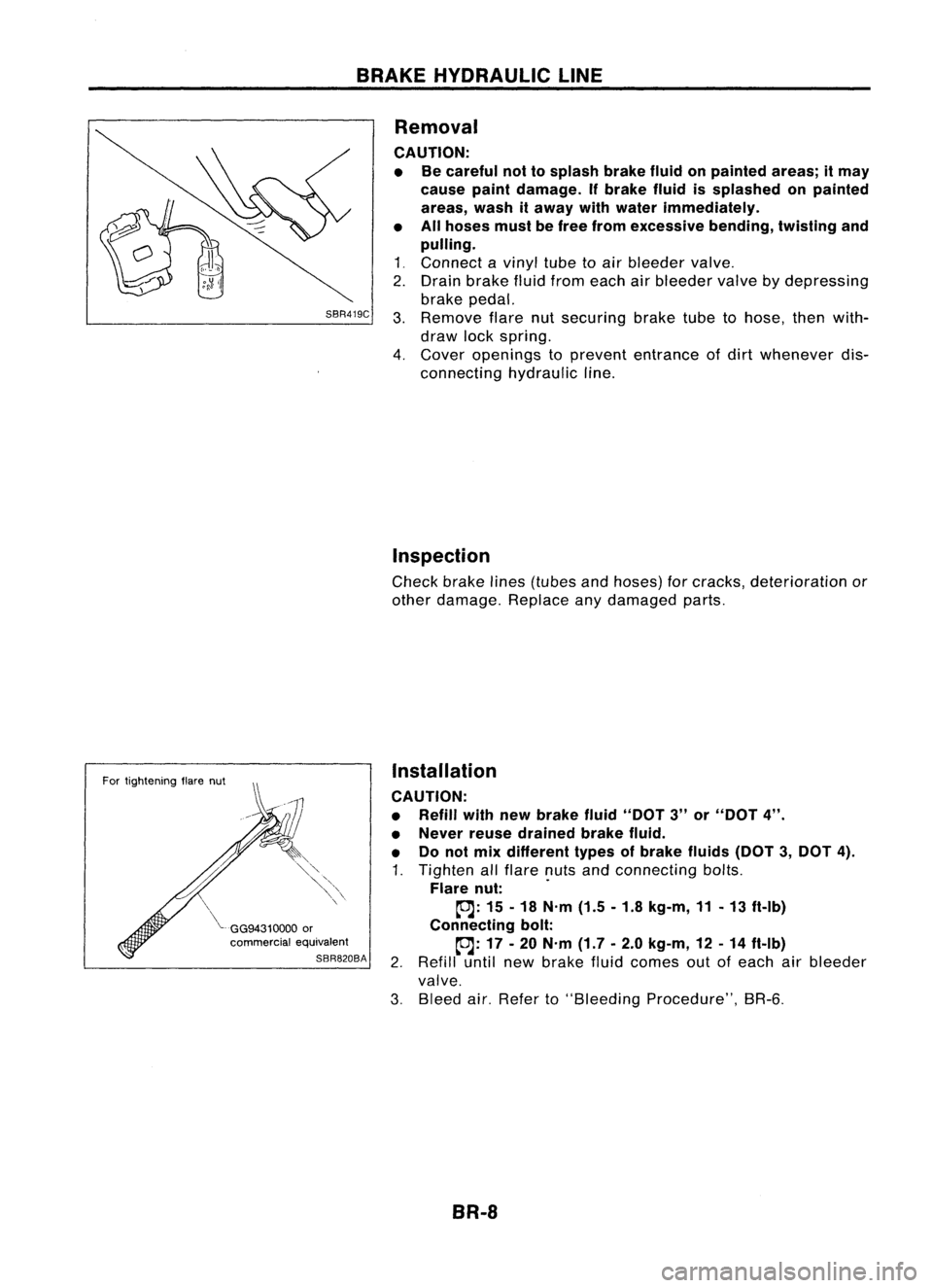
1 ~ Connect a
vinyl
tubetoair bleeder
valve~
2. Drain brake fluidfrom each airbleeder
valve
bydepressing
brake pedal.
3. Remove
flarenutsecuring braketubetohose, thenwith-
draw lockspring.
4. Cover
openings to
prevent
entrance ofdirt
whenever
dis-
connecting hydraulicline.
Inspection
Check brakelines(tubes andhoses) forcracks, deterioration or
other damage. Replaceanydamaged parts.
Installation
CAUTION:
• Refill withnewbrake fluid"DOT 3"or"DOT 4".
• Never reusedrained brakefluid.
• Donot mix different typesofbrake fluids(DOT3,DOT 4).
1. Tighten allflare nutsandconnecting bolts.
Flare nut: .
~: 15-18 N'm (1.5-1.8 kg-m, 11-13 ft-Ib)
Connecting bolt:
~: 17-20 N'm (1.7-2.0 kg-m, 12-14 ft-Ib)
2. Refill untilnewbrake fluidcomes outofeach airbleeder
valve.
3. Bleed air.Refer to"Bleeding Procedure", BR-6.
BR-8