Page 108 of 1701
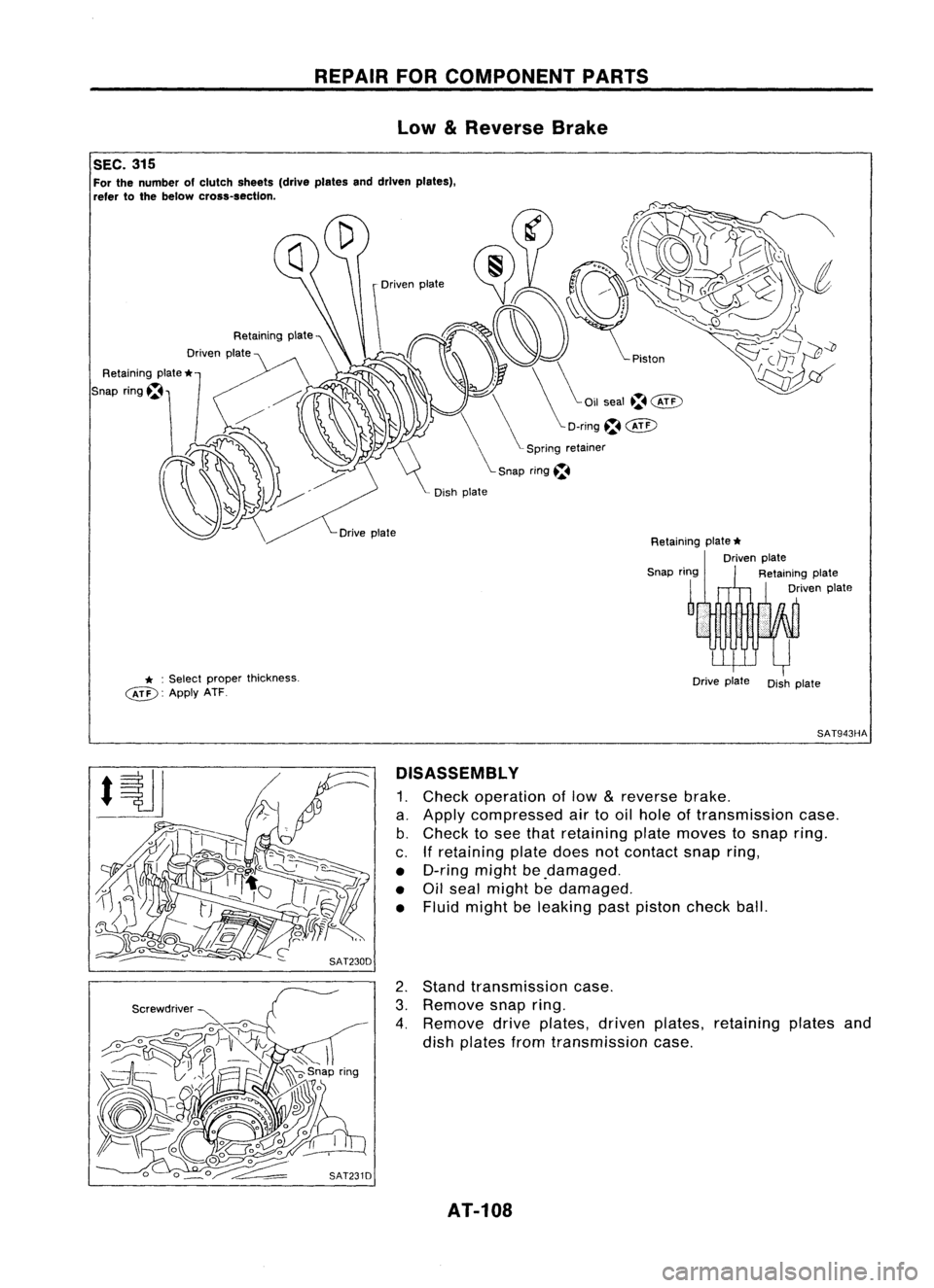
REPAIRFOR
COMPONENT PARTS
Low
&
Reverse Brake
SAT943HA
Dish
plate
Drive
plate
Retaining
plate
*
Driven plate
Retaining plate
Driven plate
Drive
plate
* :
Select
~: Applyx~~per thickness.
SEC.
315
For the numb
refer tothe b:~O~ clutch sheets (dri
cross-section
veplates anddI
,
rven plates),
DISASSEMBL Y
1. Check operat'
a. Apply co Ionoflow
&
r
b. Check tmpressed airtoo,el vherse brake
c If
0
see that
I
ole oft .
. retaining platdretaining plateransmission ca
• D-rin .eoes n
t
moves
t
se.
• Oil gmight bedama
0
contact snap
.0
snap ring.
seal might
be
ged. ring,
• FluId might bdamaged
e leak' .
Ing past piston h
c eck ball
2. Stand trans .,
3. Remove sn~l1IS~lOn case.
4. Remov .p nng.
d' ednve plate
Ish plates fromts,~riven plate
ransmlssio s,
n case. retaining
platesand
AT-108
Page 109 of 1701
REPAIRFORCOMPONENT PARTS
Low
&
Reverse Brake(Conl'd)
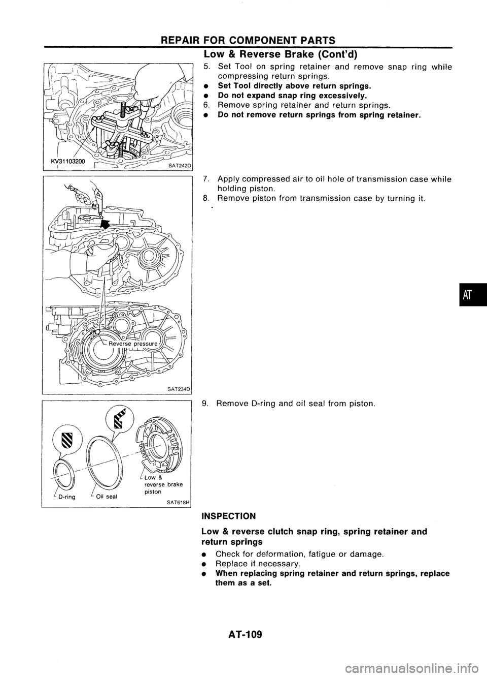
5. Set Tool onspring retainer andremove snapringwhile
compressing returnsprings.
• Set Tool directly abovereturnsprings.
• Donot expand snapringexcessively.
6. Remove springretainer andreturn springs.
• Donot remove returnsprings fromspring retainer.
7. Apply compressed airtooil hole oftransmission casewhile
holding piston.
8. Remove pistonfromtransmission case
by
turning it.
9. Remove D-ringandoilseal from piston.
piston
SAT618H
INSPECTION
Low
&
reverse clutchsnapring,spring retainer and
return springs
• Check fordeformation, fatigueordamage.
• Replace ifnecessary.
• When replacing springretainer andreturn springs, replace
them asaset.
AT-109
•
Page 110 of 1701
REPAIRFORCOMPONENT PARTS
Low
&
Reverse Brake(Coni'd)
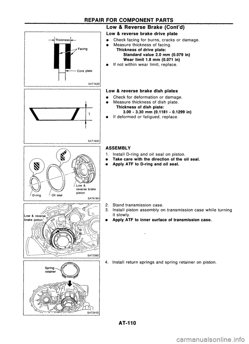
Low &reverse brakedriveplate
• Check facing forburns, cracks ordamage.
• Measure thickness offacing.
Facing Thicknessofdrive plate:
Standard value2.0mm (0.079 in)
Wear limit1.8mm (0.071 in)
• Ifnot within wearlimit,replace.
SAT162D Low
&
reverse brakedishplates
• Check fordeformation ordamage.
• Measure thickness ofdish plate.
Thickness ofdish plate:
3.00 -3.30 mm(0.1181 -0.1299 in)
• If
deformed orfatigued, replace.
SAT163D ASSEMBLY
1. Install D-ring andoilseal onpiston.
• Take carewiththedirection ofthe oilseal.
• Apply ATFtoO-ring andoilseal.
2. Stand transmission case.
3. Install piston assembly ontransmission casewhile turning
it slowly.
• Apply ATFtoinner surface oftransmission case.
4. Install returnsprings andspring retainer onpiston.
AT-110
Page 111 of 1701
SAT254E
•
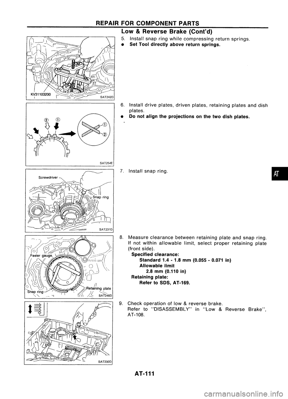
7.
Install snapring.
6.
Install driveplates, drivenplates, retaining platesanddish
plates.
• Donot align theprojections onthe two dish plates.
8. Measure clearance betweenretaining plateandsnap ring.
If not within allowable limit,select proper retaining plate
(front side).
Specified clearance:
Standard 1.4-1.8 mm (0.055 -0.071 in)
Allowable limit
2.8 mm (0.110 in)
Retaining plate:
Refer toSOS, AT-169.
9. Check operation oflow
&
reverse brake.
Refer to"DISASSEMBLY" in"Low
&
Reverse Brake",
AT-108.
REPAIR
FORCOMPONENT PARTS
Low
&
Reverse Brake(Cont'd)
5. Install snapringwhile compressing returnsprings.
• Set Tool directly abovereturnsprings.
/7
" gRetainin
g
plate
\ ~\ J/..
~6D
AT-111
Page 147 of 1701
Forwardclutch
assembly
Bearing race
m
@
ASSEMBLY
Assembly 2
- All models -
1. Remove paperrolledaround bearing retainer.
2. Install thrustwasher onbearing retainer.
• Apply petroleum jellytothrust washer.
3. Install forward clutchassembly.
• Align teethoflow
&
reverse brakedriveplates before
installing.
.. Make surethatbearing retainer sealrings arenotspread.
- Except model34X81-
4. Install bearing raceonbearing retainer.
• Apply petroleum jellytobearing race.
•
mep,:
Applypetroleum jelly.
SAT698D
Needle bearing
@
'-
(I
SAT694D
5.
Install needle bearings onrear internal gear.
• Apply petroleum jellytoneedle bearings.
• Pay attention todirection ofneedle bearing.
- Model 34X81-
4. Install thrustneedle bearing onbearing retainer.
• Apply petroleum jellytothrust bearing.
• Pay attention todirection ofthrust needle bearing.
AT-147
Page 155 of 1701
Bearingrace
Thrustwasher SAT158E ASSEMBLY
Assembly 3
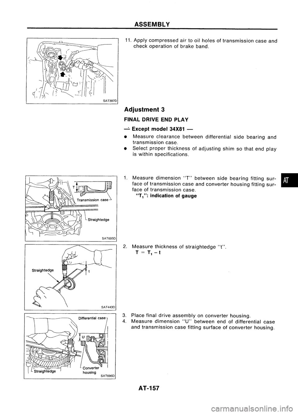
1. Remove reverseclutchassembly andinstall needle bearing
on high clutch assembly.
• Pay attention todirection ofneedle bearing.
2. Install reverse clutchassembly.
3. Install anchor endpin,washer andlock nutontransmission
case.
4. Place brake bandonoutside ofreverse clutchdrum.Tighten
. anchor endpinjust enough sobrake bandisevenly fitted
on reverse clutchdrum.
5. Place bearing raceselected intotal endplay adjustment •
step onoil pump cover.
• Apply petroleum jellytobearing race.
6. Place thrust washer selected inreverse clutchendplay step
on reverse clutchdrum.
• Apply petroleum jellytothrust washer.
7. Install oilpump assembly ontransmission case.
AT-155
Page 156 of 1701
ASSEMBLY
Assembly 3(Cont'd)
8. Tighten oilpump fixing boltstospecified torque.
9. Install O-ring toinput shaft.
• Apply ATFtoO-ring.
10. Adjust brakeband.
a. Tighten anchorendpintospecified torque.
Anchor endpin:
Ill:
3.9-5.9 N.m (0.4-0.6 kg-m, 35-52 in-Ib)
b. Back offanchor endpintwo and ahalf turns.
c. While holding anchorendpin,tighten locknut.
AT-156
Page 157 of 1701
SAT397D
Straightedge SAT695D
SAT696D ASSEMBLY
11. Apply compressed airtooil holes oftransmission caseand
check operation ofbrake band.
Adjustment 3
FINAL DRIVE ENDPLAY
_. Except model34X81-
• Measure clearance betweendifferential sidebearing and
transmission case.
• Select proper thickness ofadjusting shimsothat end play
is within specifications.
1. Measure dimension 'T"between sidebearing fittingsur-•
face oftransmission caseandconverter housingfittingsur-
face oftransmission case.
"T/':
indication ofgauge
2. Measure thickness ofstraightedge "t".
T
= T
1 -
t
3. Place finaldrive assembly onconverter housing.
4. Measure dimension "U"between endofdifferential case
and transmission casefitting surface ofconverter housing.
AT-157