SRA696A
SRA697A
S
Control rod
Lateral link
~H";""I"
ITorsion
beam
SRA698AREAR
SUSPENSION
Removal andInstallation
CAUTION:
• Before removing therear suspension assembly,disconnect
the ABS wheel sensor fromtheassembly. Failuretodo so
may result indamage tothe sensor wiresandthesensor
becoming inoperative.
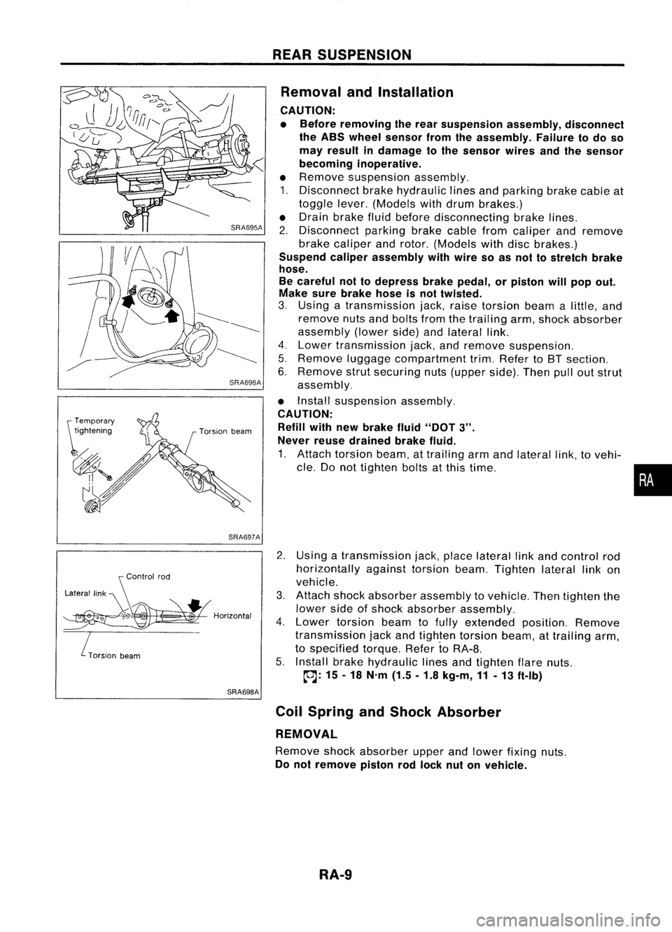
• Remove suspension assembly.
1. Disconnect brakehydraulic linesandparking brakecableat
toggle lever.(Models withdrum brakes.)
• Drain brake fluidbefore disconnecting brakelines.
2. Disconnect parkingbrakecablefromcaliper andremove
brake caliper androtor. (Models withdiscbrakes.)
Suspend caliperassembly withwire soasnot tostretch brake
hose.
Be careful nottodepress brakepedal, orpiston willpop out.
Make surebrake hoseisnot twisted.
3. Using atransmission jack,raise torsion beamalittle, and
remove nutsandbolts fromthetrailing arm,shock absorber
assembly (lowerside)andlateral link.
4. Lower transmission jack,andremove suspension.
5. Remove luggagecompartment trim.Refer toBT section.
6. Remove strutsecuring nuts(upper side).Thenpulloutstrut
assembly.
• Install suspension assembly.
CAUTION: Refill withnewbrake fluid"DOT
3".
Never reusedrained brakefluid.
1. Attach torsion beam,attrailing armandlateral link,tovehi-
cle. Donot tighten boltsatthis time.
2. Using atransmission jack,place lateral linkand control rod
horizontally againsttorsionbeam.Tighten laterallinkon
vehicle.
3. Attach shockabsorber assembly tovehicle. Thentighten the
lower sideofshock absorber assembly.
4. Lower torsion beamtofully extended position.Remove
transmission jackandtighten torsion beam,attrailing arm,
to specified torque.RefertoRA-8.
5. Install brakehydraulic linesandtighten flarenuts.
~: 15-18 N'm (1.5.1.8 kg-m,11-13 ft-Ib)
Coil Spring andShock Absorber
REMOVAL
Remove shockabsorber upperandlower fixing nuts.
Do not remove pistonrodlock nutonvehicle.
RA-9
•
SST491B
SST090B ON-VEHICLE
SERVICE
Bleeding Hydraulic System
1. Raise frontendofvehicle untilwheels areclear ofthe
ground.
2. Add fluid intooiltank tospecified level.Thenquickly turn
steering wheelfullytoright andleftand lightly touchsteer-
ing stoppers.
Repeat steering wheeloperation untilfluid level nolonger
decreases.
3. Start engine.
Repeat step2.above.
• Incomplete airbleeding willcause thefollowing tooccur.
When thishappens, bleedairagain.
a. Air bubbles inreservoir tank
b. Clicking noiseinoil pump
c. Excessive buzzinginoil pump
Fluid noise mayoccur inthe valve oroil pump. Thisiscommon
when thevehicle isstationary orwhile turning thesteering
wheel slowly. Thisdoes notaffect theperformance ordurabil-
ity ofthe system.
Checking SteeringWheelTurning Force(For
power steering)
1. Park vehicle onalevel, drysurface andsetparking brake.
2. Start engine.
3. Bring power steering fluiduptoadequate operating temper-
ature. [Make suretemperature offluid isapproximately 60
to 80°C (140to176°F).]
Tires needtobe inflated tonormal pressure.
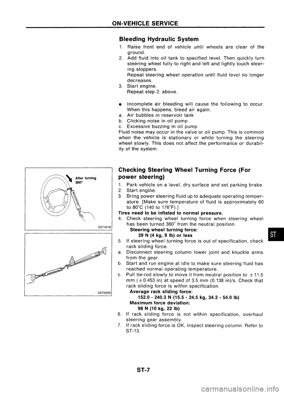
4. Check steering wheelturning forcewhen steering wheel
has been turned 360°from theneutral position.
Steering wheelturning force: •
39 N(4 kg, 9Ib) orless
5.
If
steering wheelturning forceisout ofspecification, check
rack sliding force.
a. Disconnect steeringcolumnlowerjointandknuckle arms
from thegear.
b. Start andrunengine atidle tomake suresteering fluidhas
reached normaloperating temperature.
c. Pull tie-rod slowlytomove itfrom neutral position to
::l::
11.5
mm
(::l::
0.453 in)atspeed of3.5 mm (0.138 in)/s.Check that
rack sliding forceiswithin specification.
Average racksliding force:
152.0 -240.3 N(15.5 -24.5 kg,34.2 -54.0 Ib)
Maximum forcedeviation:
98 N(10 kg, 22Ib)
6.
If
rack sliding forceisnot within specification, overhaul
steering gearassembly.
7. Ifrack sliding forceisOK, inspect steering column.Referto
ST-13.
ST-7