1995 NISSAN ALMERA N15 open hood
[x] Cancel search: open hoodPage 225 of 1701
BODYEND
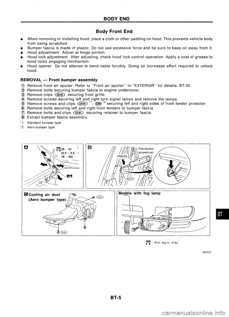
Body Front End
• When removing orinstalling hood,placeacloth orother padding onhood. Thisprevents vehiclebody
from being scratched.
• Bumper fasciaismade ofplastic. Donot use excessive forceandbesure tokeep oilaway fromit.
• Hood adjustment: Adjustathinge portion.
• Hood lockadjustment: Afteradjusting, checkhoodlockcontrol operation. Applyacoat ofgrease to
hood locks engaging mechanism.
• Hood opener: Donot attempt tobend cable forcibly. Doingsoincreases effortrequired tounlock
hood.
REMOVAL -Front bumper assembly
CD
Remove frontairspolier. Referto"Front
air
spoiler" in"EXTERIOR" fordetails, BT-33.
@
Remove boltssecuring bumperfasciatoengine undercover.
CID
Remove clips
@QD
securing frontgrille.
@
Remove screwssecuring leftand right turnsignal lampsandremove thelamps.
@
Remove screwsandclips
@W
*1,
@
*2
securing
leftand right sides offront fender protector.
@)
Remove boltssecuring leftand right front fenders tobumper fascia.
([) Remove boltsandclips
@W
securing retainertobumper fascia.
@)
Extract bumper fasciaassembly.
*1: Standard bumpertype
*2: Aero bumper type
to.J:
N'm (kg-m, ft-Ib)
SBT037
B1-5
•
Page 756 of 1701
SEF217M
•
START
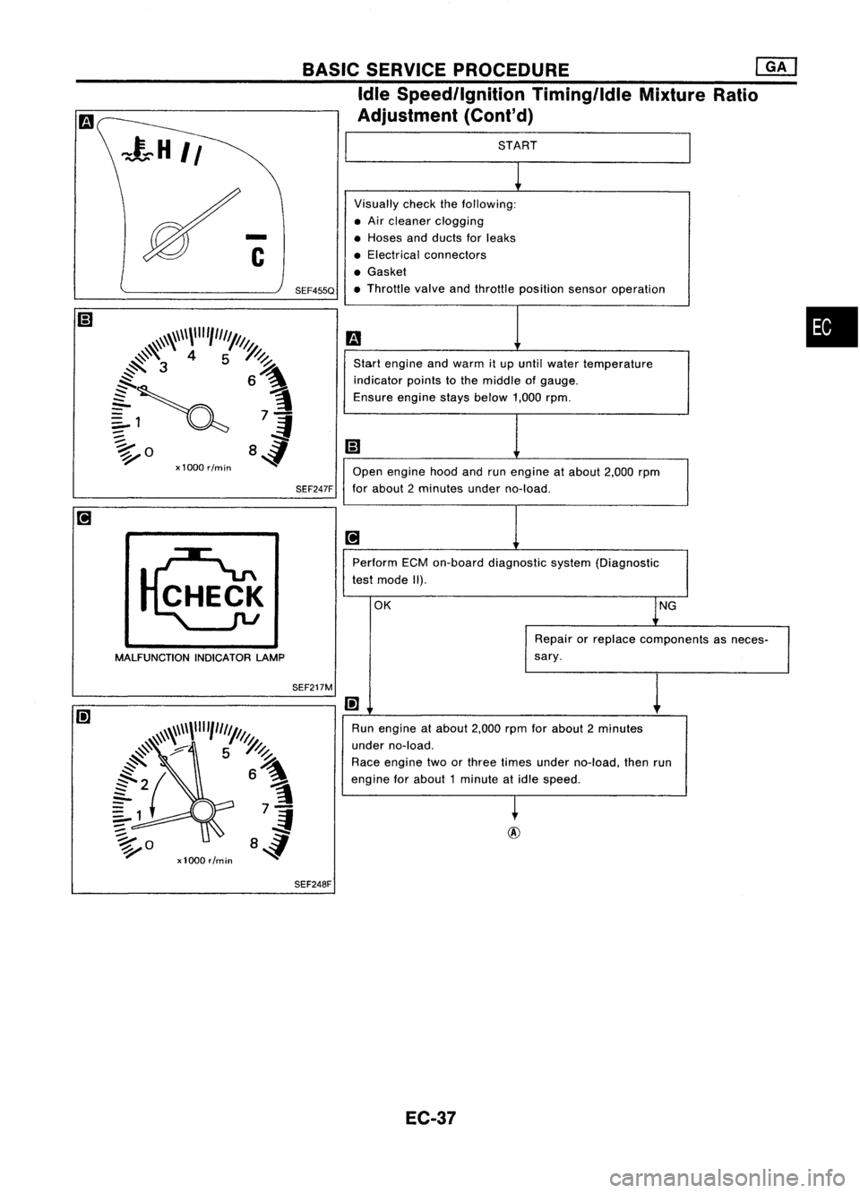
Visually checkthefollowing:
• Air cleaner clogging
• Hoses andducts forleaks
• Electrical connectors
• Gasket
• Throttle valveandthrottle position sensoroperation
m
Start engine andwarm itup until water temperature
indicator pointstothe middle ofgauge.
Ensure enginestaysbelow 1,000rpm.
iii
Open engine hoodandrunengine atabout 2,000rpm
for about 2minutes underno-load.
[iJ
Perform ECMon-board diagnostic system(Diagnostic
test mode II).
OK lNG
Repair orreplace components asneces-
sary.
I!]
1
Run engine atabout 2,000rpmforabout 2minutes
under no-load.
Race engine twoorthree times under no-load, thenrun
engine forabout 1minute atidle speed.
~
BASIC
SERVICE PROCEDURE
eM]
Idle Speed/Ignition Timing/IdleMixtureRatio
Adjustment (Cont'd)
SEF247F
SEF455Q
MALFUNCTION INDICATORLAMP
SEF248F
EC-37
Page 963 of 1701
@
START
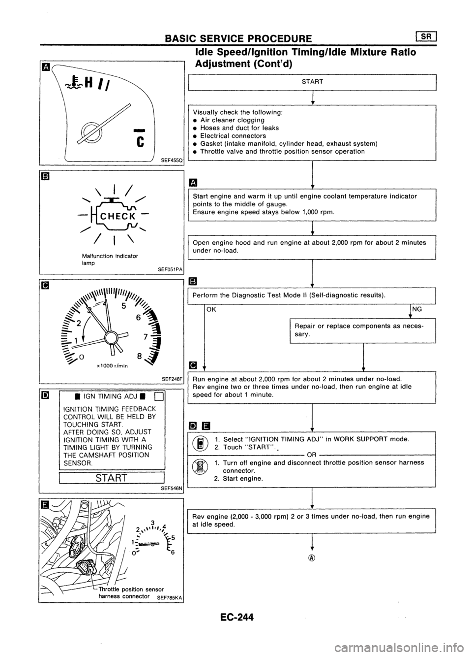
Visually checkthefollowing:
• Air cleaner clogging
• Hoses andduct forleaks
• Electrical connectors
• Gasket (intakemanifold, cylinderhead,exhaust system)
• Throttle valveandthrottle position sensoroperation
m
Start engine andwarm itup until engine coolant temperature indicator
points tothe middle ofgauge.
Ensure enginespeedstaysbelow 1,000rpm.
1
Open engine hoodandrunengine atabout 2,000rpmforabout 2minutes
under no-load.
Ii]
Perform theDiagnostic TestMode
1\
(Self-diagnostic results).
OK ~NG
Repair orreplace components asneces-
sary.
[!J
Run engine atabout 2,000rpmforabout 2minutes underno-load.
Rev engine twoorthree times under no-load, thenrunengine atidle
speed forabout 1minute .
li]1!I
00
1.
Select "IGNITION TIMINGADJ"inWORK SUPPORT mode.
2. Touch "START" .
.
OR
00
1.
Turn offengine anddisconnect throttleposition sensorharness
connector.
2. Start engine.
Rev engine (2,000-3,000 rpm)2or 3times under no-load, thenrunengine
at idle speed.
t
Throttle position sensor
harness connector SEF785KASEF051PA
BASIC
SERVICE PROCEDURE Em
Idle Speedllgnition TiminglldleMixtureRatio
Adjustment (Cont'd)
SEF248F
SEF455Q
Malfunction indicator
lamp \
I/
'~,,/
- CHECK-
,,/
........
/ I\
Ii] •IGN TIMING ADJ.
D
IGNITION TIMINGFEEDBACK
CONTROL WILLBEHELD BY
TOUCHING START.
AFTER DOING SO,ADJUST
IGNITION TIMINGWITHA
TIMING LIGHTBYTURNING
THE CAMSHAFT POSITION
SENSOR.
I
START
I
SEF546N
EC-244
Page 990 of 1701
TROUBLEDIAGNOSIS -General Descrip_ti_on
1S_R_'
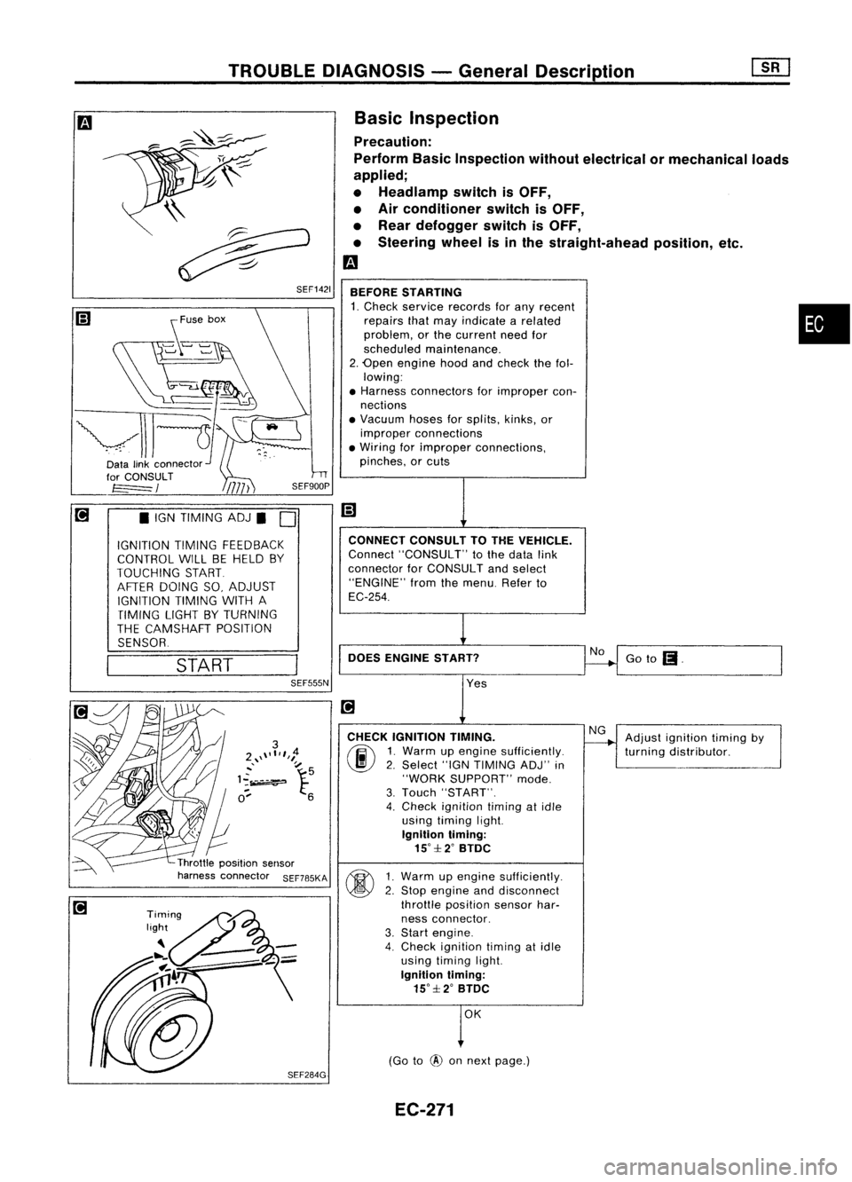
Basic Inspection
Precaution:
Perform BasicInspection withoutelectrical ormechanical loads
applied;
• Headlamp switchisOFF,
• Air conditioner switchisOFF,
• Rear defogger switchisOFF,
• Steering wheelisinthe straight-ahead position,etc.
m
BEFORE STARTING
1. Check service records forany recent •
repairs thatmay indicate arelated
problem, orthe current needfor
scheduled maintenance.
2. Open engine hoodandcheck thefol-
lowing:
• Harness connectors forimproper con-
nections
• Vacuum hosesforsplits, kinks,or
improper connections
• Wiring forimproper connections,
pinches, orcuts
Goto
(I.
No
CONNECT
CONSULTTOTHE VEHICLE.
Connect "CONSULT" tothe data link
connector forCONSULT andselect
"ENGINE" fromthemenu. Referto
EC-254.
DOES ENGINE START?
\\
~
~ SEF1421
START
•
IGN TIMING ADJ.
0
IGNITION TIMINGFEEDBACK
CONTROL WILLBEHELD BY
TOUCHING START
AFTER DOING SO,ADJUST
IGNITION TIMINGWITHA
TIMING LIGHTBYTURNING
THE CAMSHAFT POSITION
SENSOR.
SEF555N
Yes
CHECK IGNITION TIMING.
(ij\
1.Warm upengine sufficiently.
~ 2.Select "IGNTIMING ADJ"in
"WORK SUPPORT" mode.
3. Touch "START".
4. Check ignition timingatidle
using timing light.
Ignition timing:
15°::f:2° BTDC
~ 1Warm upengine sufficiently.
~ 2:
Stop engine anddisconnect
throttle position sensorhar-
ness connector.
3. Start engine.
4. Check ignition timingatidle
using timing light.
Ignition timing:
15°::f:2° BTDC
OK
(Go to
@
onnext page.) Adjust
ignition timingby
turning distributor.
EC-271
Page 1368 of 1701
Normallyopen
HOW
TOREAD WIRING DIAGRAMS
Description (Cont'd)
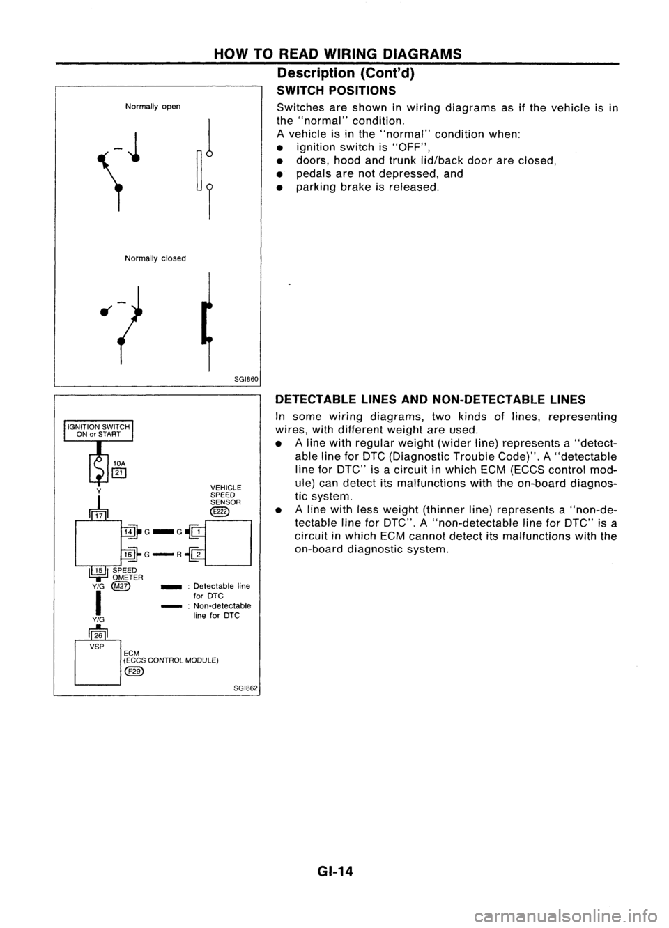
SWITCH POSITIONS
Switches areshown inwiring diagrams asifthe vehicle isin
the "normal" condition.
A vehicle isin the "normal" conditionwhen:
• ignition switchis"OFF",
• doors, hoodandtrunk lid/back doorareclosed,
• pedals arenotdepressed, and
• parking brakeisreleased.
Normally closed
5GI860DETECTABLE LINESANDNON-DETECTABLE LINES
In some wiring diagrams, twokinds oflines, representing
wires, withdifferent weightareused.
• Aline with regular weight(widerline)represents a"detect-
able lineforDTC (Diagnostic TroubleCode)".A"detectable
line forDTC" isacircuit inwhich ECM(ECCS control mod-
ule) candetect itsmalfunctions withtheon-board diagnos-
tic system.
• Aline with lessweight (thinner line)represents a"non-de-
tectable lineforDTC", A"non-detectable lineforDTC" isa
circuit inwhich ECMcannot detectitsmalfunctions withthe
on-board diagnostic system.
SGI862
_
:Detectable line
for DTC
- :Non-detectable
line forDTC
Y
~ VEHICLE
SPEED SENSOR
@
lill-G_G~
llli-G-R~
I~I
SPEED
.,=
OMETER
Y/G
@Z)
I
Y/G
[]26
VSP ECM
(ECCS CONTROL MODULE)
@)
GI-14
Page 1428 of 1701
TROUBLEDIAGNOSES
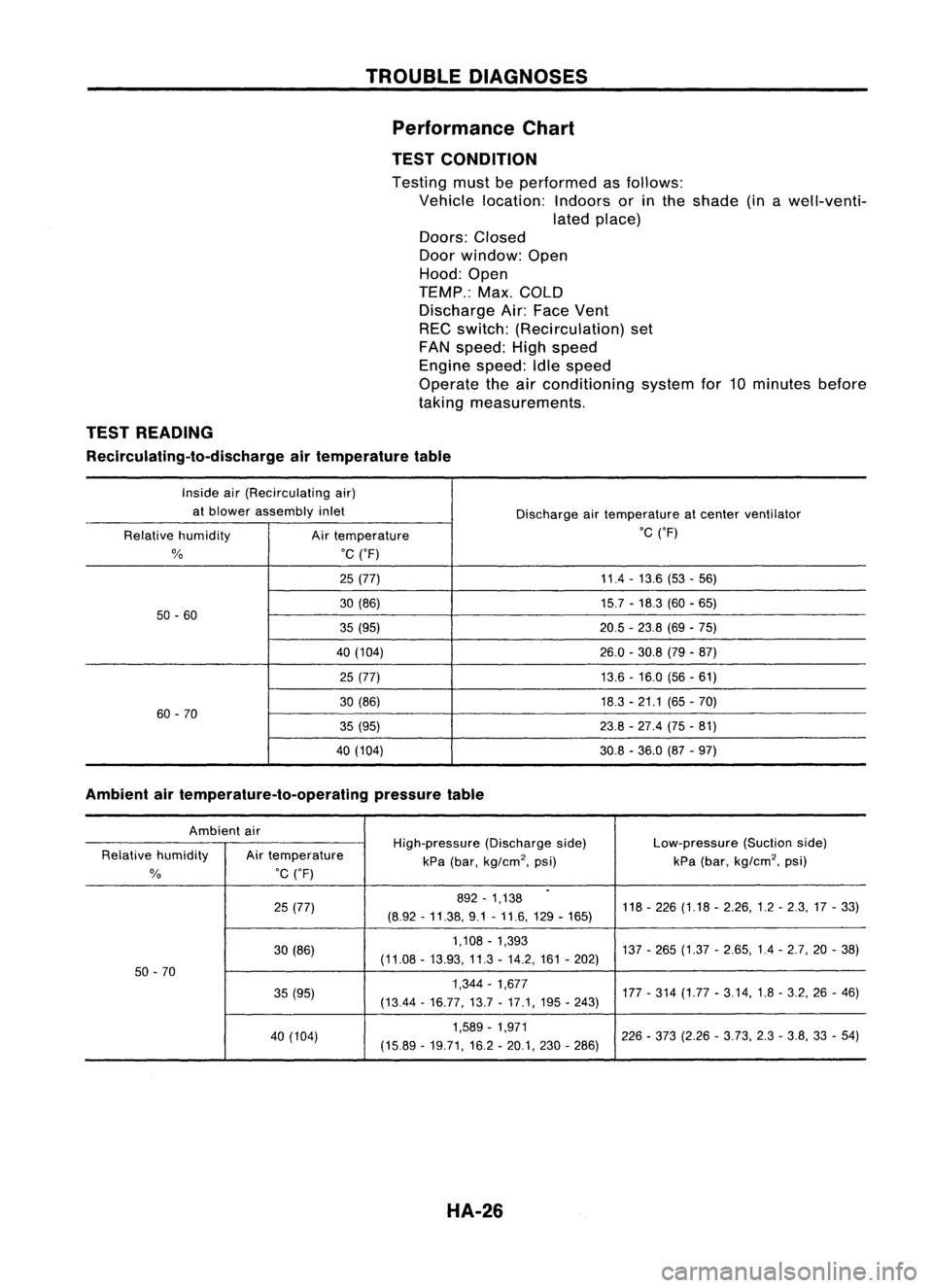
Performance Chart
TEST CONDITION
Testing mustbeperformed asfollows:
Vehicle location: Indoorsorinthe shade (inawell-venti-
lated place)
Doors: Closed
Door window: Open
Hood: Open
TEMP.: Max.COLD
Discharge Air:Face Vent
REC switch: (Recirculation) set
FAN speed: Highspeed
Engine speed:Idlespeed
Operate theairconditioning systemfor10minutes before
taking measurements.
TEST READING
Recirculating-to-discharge airtemperature table
Inside air(Recirculating air)
at blower assembly inlet
Dischargeairtemperature atcenter ventilator
Relative humidity
Airtemperature .C
('F)
%
.C
('F)
25 (77) 11.4
-13.6 (53-56)
30 (86) 15.7-18.3 (60-65)
50 -60
35(95) 20.5-23.8 (69-75)
40 (104) 26.0-30.8 (79-87)
25 (77) 13.6-16.0 (56-61)
30 (86) 18.3-21.1 (65-70)
60 -70
35(95) 23.8-27.4 (75-81)
40 (104) 30.8-36.0 (87-97)
Ambient airtemperature-to-operating pressuretable
Ambient air
High-pressure(Dischargeside) Low-pressure
(Suctionside)
Relative humidity Airtemperature
kPa(bar,
kg/cm
2,
psi) kPa
(bar,
kg/cm
2,
psi)
%
.C
('F)
.
25 (77) 892
-1,138
118-226 (1.18 -2.26,1.2 -2.3,17 -33)
(8.92 -11.38, 9.1-11.6,129 -165)
30 (86) 1,108
-1,393
137-265 (1.37 -2.65,1.4 -2.7,20 -38)
(11.08 -13.93, 11.3-14.2, 161-202)
50 -70
35(95) 1,344
-1,677
177-314 (1.77 -3.14,1.8 -3.2, 26-46)
(1344 -16.77,13.7 -17.1, 195-243)
40 (104) 1,589
-1,971
226-373 (2.26 -3.73, 2.3-3.8, 33-54)
(15.89 -19.71,16.2 -20.1, 230-286)
HA-26
Page 1492 of 1701
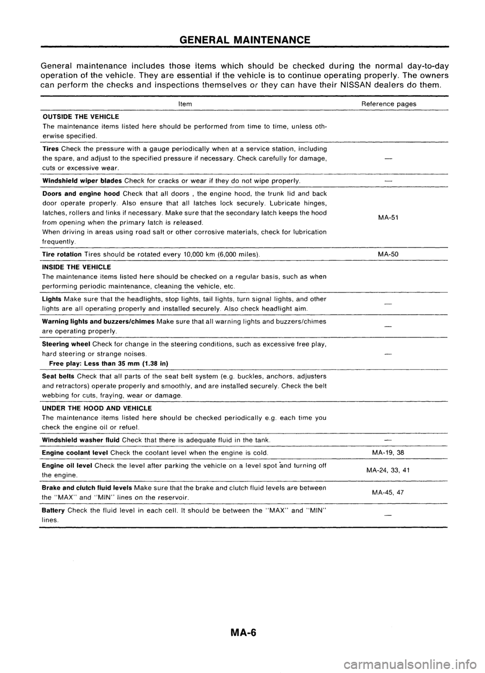
GENERALMAINTENANCE
General maintenance includesthoseitemswhich should bechecked duringthenormal day-to-day
operation ofthe vehicle. Theyareessential ifthe vehicle isto continue operating properly.Theowners
can perform thechecks andinspections themselves orthey canhave theirNISSAN dealersdothem.
Item
OUTSIDE THEVEHICLE
The maintenance itemslistedhereshould beperformed fromtimetotime, unless oth-
erwise specified.
Tires
Check thepressure withagauge periodically whenataservice station, including
the spare, andadjust tothe specified pressureifnecessary. Checkcarefully fordamage,
cuts orexcessive wear.
Windshield wiperblades
Checkforcracks orwear ifthey donot wipe properly.
Doors andengine hood
Check thatalldoors, theengine hood,thetrunk lidand back
door operate properly. Alsoensure thatalllatches locksecurely. Lubricate hinges,
latches, rollersandlinks ifnecessary. Makesurethatthesecondary latchkeeps thehood
from opening whentheprimary latchisreleased.
When driving inareas usingroadsaltorother corrosive materials, checkforlubrication
frequently.
Tire rotation
Tiresshould berotated every
10,000
km
(6,000
miles).
INSIDE THEVEHICLE
The maintenance itemslistedhereshould bechecked onaregular basis,suchaswhen
performing periodicmaintenance, cleaningthevehicle, etc.
Lights
Makesurethattheheadlights, stoplights, taillights, turnsignal lights,andother
lights arealloperating properlyandinstalled securely. Alsocheck headlight aim.
Warning lightsandbuzzers/chimes
Makesurethatallwarning lightsandbuzzers/chimes
are operating properly.
Steering wheel
Check forchange inthe steering conditions, suchasexcessive freeplay,
hard steering orstrange noises.
Free play: Lessthan35mm (1.38 in)
Seat belts
Check thatallparts ofthe seat beltsystem (e.g.buckles, anchors, adjusters
and retractors) operateproperly andsmoothly, andareinstalled securely. Checkthebelt
webbing forcuts, fraying, wearordamage.
UNDER THEHOOD ANDVEHICLE
The maintenance itemslisted hereshould bechecked periodically e.g.each timeyou
check theengine oilorrefuel.
Windshield washerfluid
Check thatthere isadequate fluidinthe tank.
Engine coolant level
Check thecoolant levelwhen theengine iscold.
Engine oillevel
Check thelevel afterparking thevehicle onalevel spotandturning off
the engine.
Brake andclutch fluidlevels
Makesurethatthebrake andclutch fluidlevels arebetween
the "MAX" and"MIN" linesonthe reservoir.
Battery
Checkthefluid level ineach cell.Itshould bebetween the"MAX" and"MIN"
lines.
MA-6
Reference
pages
MA-51
MA-50
MA-19,38
MA-24, 33,41
MA-45,47
Page 1538 of 1701
CHASSISANDBODY MAINTENANCE
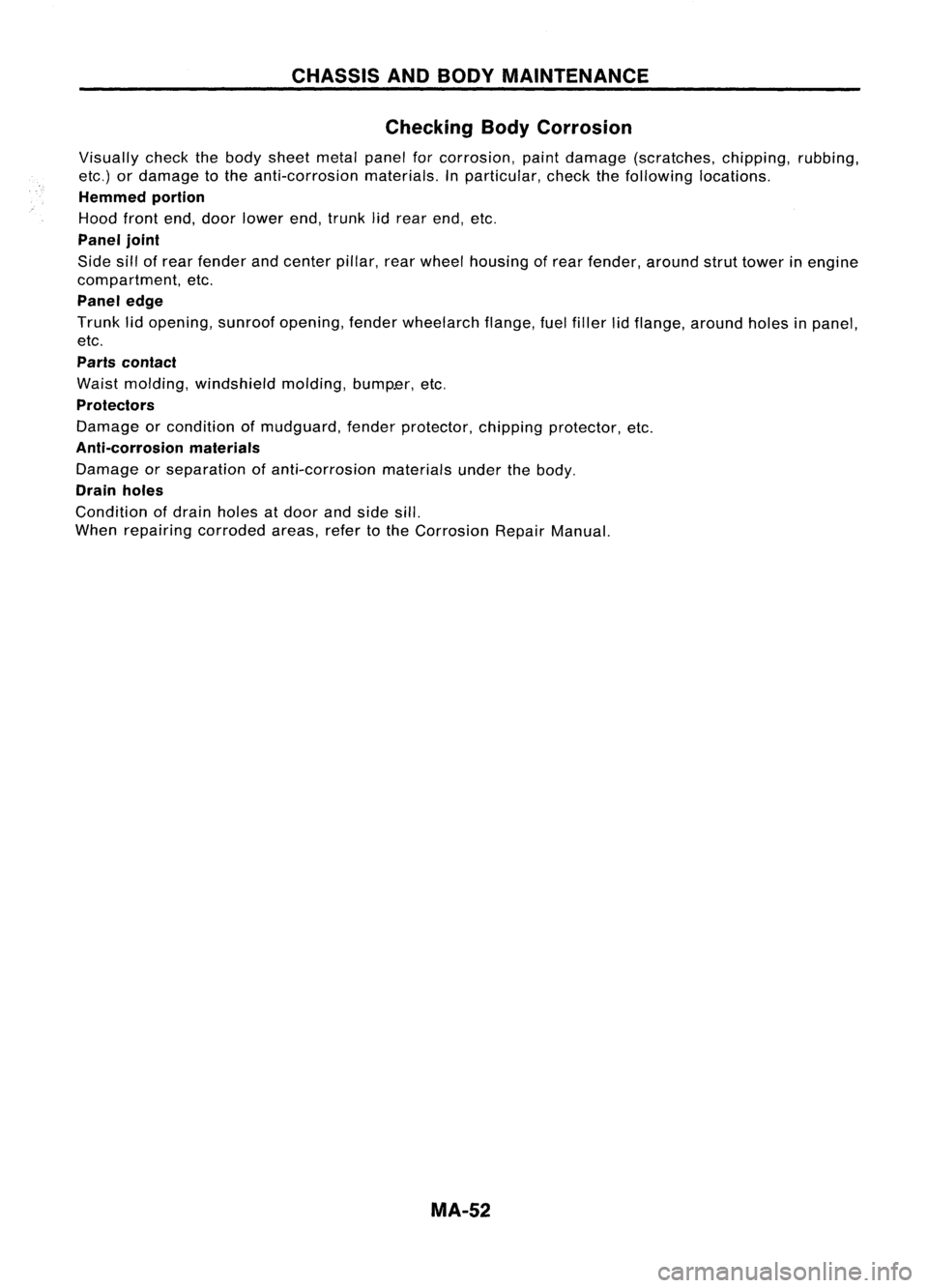
Checking BodyCorrosion
Visually checkthebody sheet metalpanelforcorrosion, paintdamage (scratches, chipping,rubbing,
etc.) ordamage tothe anti-corrosion materials.Inparticular, checkthefollowing locations.
Hemmed portion
Hood frontend,door lower end,trunk lidrear end, etc.
Panel joint
Side sillofrear fender andcenter pillar,rearwheel housing ofrear fender, aroundstruttower inengine
compartment, etc.
Panel edge
Trunk lidopening, sunroofopening, fenderwheelarch flange,fuelfiller lidflange, around holesinpanel,
etc.
Parts contact
Waist molding, windshield molding,bump.er,etc.
Protectors
Damage orcondition ofmudguard, fenderprotector, chippingprotector, etc.
Anti-corrosion materials
Damage orseparation ofanti-corrosion materialsunderthebody.
Drain holes
Condition ofdrain holes atdoor andside sill.
When repairing corrodedareas,refertothe Corrosion RepairManual.
MA-52