Page 688 of 1701

ON-VEHICLESERVICE
Front Wheel Alignment
Before checking frontwheel alignment, besure tomake apre-
liminary inspection (Unladen*).
*: Fuel, radiator coolantandengine oilfull. Spare tire,jack,
hand tools andmats indesignated positions.
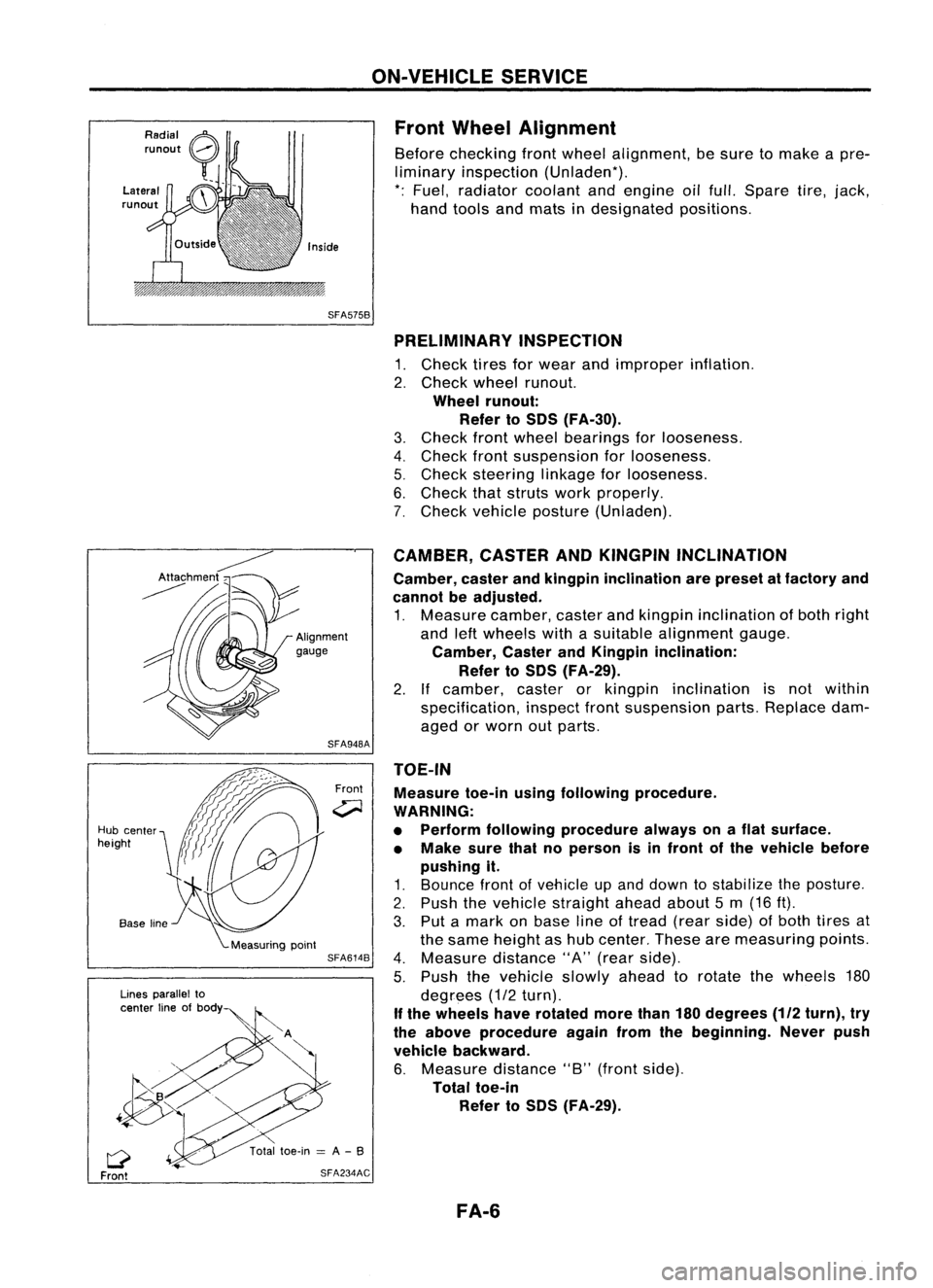
SFA575B PRELIMINARY INSPECTION
1. Check tiresforwear andimproper inflation.
2. Check wheelrunout.
Wheel runout:
Refer toSOS (FA-30).
3. Check frontwheel bearings forlooseness.
4. Check frontsuspension forlooseness.
5. Check steering linkageforlooseness.
6. Check thatstruts workproperly.
7. Check vehicle posture (Unladen).
TOE-IN Measure toe-inusingfollowing procedure.
WARNING:
• Perform following procedure alwaysonaflat surface.
• Make surethatnoperson isin front ofthe vehicle before
pushing it.
1. Bounce frontofvehicle upand down tostabilize theposture.
2. Push thevehicle straight aheadabout5m (16 ft).
3. Put amark onbase lineoftread (rearside) ofboth tires at
the same height ashub center. Thesearemeasuring points.
4. Measure distance"A"(rear side).
5. Push thevehicle slowlyaheadtorotate thewheels 180
degrees (1/2turn).
If the wheels haverotated morethan180degrees
(112
turn), try
the above procedure againfromthebeginning. Neverpush
vehicle backward.
6. Measure distance"B"(front side).
Total toe-in
Refer toSOS (FA-29).
CAMBER,
CASTERANDKINGPIN INCLINATION
Camber, casterandkingpin inclination arepreset atfactory and
cannot beadjusted.
1. Measure camber,casterandkingpin inclination ofboth right
and leftwheels withasuitable alignment gauge.
Camber, CasterandKingpin inclination:
Refer toSOS (FA-29).
2. Ifcamber, casterorkingpin inclination isnot within
specification, inspectfrontsuspension parts.Replace dam-
aged orworn outparts.
Front
SFA948A
SFA614B
SFA234AC
Lines
parallel to
center lineofbody
Q
Front
Hub
center
height
FA-6
Page 1270 of 1701

SEM083DCYLINDER
HEAD
Inspection (Cont'd)
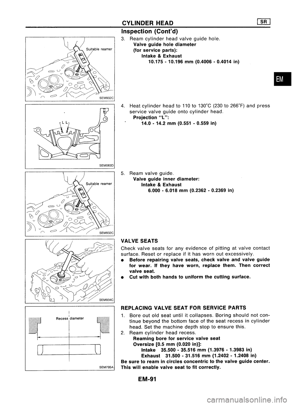
3. Ream cylinder headvalve guide hole.
Valve guide holediameter
(for service parts):
Intake
&
Exhaust
10.175 -10.196 mm(0.4006 -0.4014 in)
4. Heat cylinder headto110 to130°C (230to266°F) andpress
service valveguide ontocylinder head.
Projection
"L":
14.0 -14.2 mm(0.551 -0.559 in)
•
r
I
Recess
I
diameter
I
SEM795A
5.
Ream valveguide.
Valve guide innerdiameter:
Intake
&
Exhaust
6.000 -6.018 mm(0.2362 -0.2369 in)
VALVE SEATS
Check valveseatsforany evidence ofpitting atvalve contact
surface. Resetorreplace ifithas worn outexcessively.
• Before repairing valveseats, checkvalveandvalve guide
for wear. Ifthey have worn, replace them.Thencorrect
valve seat.
• Cut with both hands touniform thecutting surface.
REPLACING VALVESEATFORSERVICE PARTS
1. Bore outoldseat until
it
collapses. Boringshould notcon-
tinue beyond thebottom faceofthe seat recess incylinder
head. Setthemachine depthstoptoensure this.
2. Ream cylinder headrecess.
Reaming boreforservice valveseat
Oversize [0.5mm (0.020 in)]:
Intake 35.500-35.516 mm(1.3976 -1.3983 in)
Exhaust 31.500.31.516 mm(1.2402 -1.2408 in)
Be sure toream incircles concentric tothe valve guide center.
This willenable valveseattofit correctly.
EM-91
Page 1613 of 1701

ON-VEHICLESERVICE
Rear Wheel Alignment
PRELIMINARY INSPECTION
Make following checks.Adjust,repairorreplace ifnecessary.
• Check tiresforwear andforimproper inflation.
• Check rearwheel bearings forexcessive play.
• Check wheelrunout.
Wheel runout: RefertoSOS inFA section.
• Check thatrear shock absorber worksproperly.
• Check rearaxleandrear suspension partsforexcessive
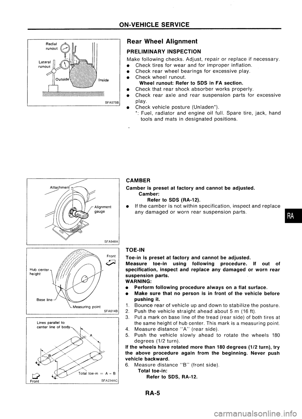
SFA575B
play.
• Check vehicle posture (Unladen*).
*: Fuel, radiator andengine oilfull. Spare tire,jack, hand
tools andmats indesignated positions.
•
CAMBER
Camber ispreset atfactory andcannot beadjusted.
Camber: Refer toSOS (RA-12).
• Ifthe camber isnot within specification, inspectandreplace
any damaged orworn rearsuspension parts.
TOE-IN
Toe-in ispreset atfactory andcannot beadjusted.
Measure toe-inusingfollowing procedure. Ifout of
specification, inspectandreplace anydamaged orworn rear
suspension parts.
WARNING:
• Perform following procedure alwaysonaflat surface.
• Make surethatnoperson isin front ofthe vehicle before
pushing it.
1. Bounce rearofvehicle upand down tostabilize theposture.
2. Push thevehicle straight aheadabout5m (16
ft).
3. Putamark onbase lineofthe tread (rearside) ofboth tires at
the same height ofhub center. Thismark isameasuring point.
4. Measure distance"A"(rear side).
5. Push thevehicle slowlyaheadtorotate thewheels 180
degrees (1/2turn).
If the wheels haverotated morethan180degrees (1/2turn), try
the above procedure againfromthebeginning. Neverpush
vehicle backward.
6. Measure distance"B"(front side).
Total toe-in:
Refer toSOS, RA-12.
Front
SFA948A
SFA614B
SFA234AC
Lines
parallel to
center lineofbOdY~
Q
Front
Hub
center
height
RA-5