1995 NISSAN ALMERA N15 tire type
[x] Cancel search: tire typePage 447 of 1701
Bulbcover
SEL995K HEADLAMP
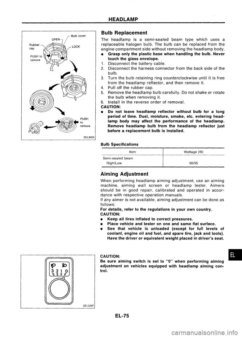
Bulb Replacement
The headlamp isasemi-sealed beamtypewhich usesa
replaceable halogenbulb.Thebulb canbereplaced fromthe
engine compartment sidewithout removing theheadlamp body.
• Grasp onlytheplastic basewhen handling thebulb. Never
touch theglass envelope.
1. Disconnect thebattery cable.
2. Disconnect theharness connector fromtheback sideofthe
bulb.
3. Turn thebulb retaining ringcounterclockwise until
it
is free
from theheadlamp reflector,andthen remove it.
4. Pull offthe rubber cap.
5. Remove theheadlamp bulbcarefully. Donot shake orrotate
the bulb when removing it.
6. Install inthe reverse orderofremoval.
CAUTION:
• Do not leave headlamp reflector withoutbulbforalong
period oftime. Dust,moisture, smoke,etc.entering head-
lamp bodymayaffect theperformance ofthe head lamp.
Remove headlamp bulbfrom thehead lamp reflector just
before areplacement bulbisinstalled.
Bulb Specifications
Item
Semi-sealed beam
High/Low Wattage
(W)
60/55
f>
to
3 21 0
~ nOD
o
SEL226PAiming
Adjustment
When performing headlamp aiming adjustment, useanaiming
machine, aimingwallscreen orheadlamp tester.Aimers
should beingood repair, calibrated andoperated inaccor-
dance withrespective operationmanuals.
If any aimer isnot available, aimingadjustment canbedone as
follows:
For details, refertothe regulations inyour owncountry.
CAUTION:
• Keep alltires inflated tocorrect pressures.
• Place vehicle andtester onone and same flatsurface.
• See thatvehicle isunloaded (exceptforfull levels of
coolant, engineoiland fuel, andspare tire,jack andtools).
Have thedriver orequivalent weightplaced indriver's seat.
CAUTION: •
Be sure aiming switchisset to
"0"
when performing aiming
adjustment onvehicles equipped withheadlamp aiming con-
trol.
EL-75
Page 473 of 1701
GEL001EXTERIOR
LAMP
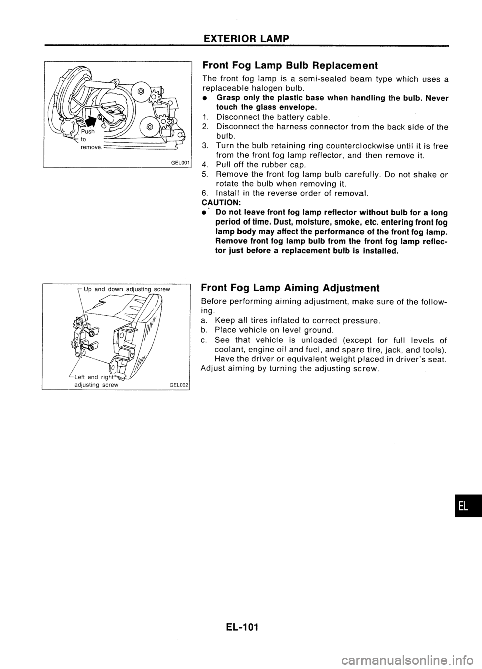
Front FogLamp BulbReplacement
The front foglamp isasemi-sealed beamtypewhich usesa
replaceable halogenbulb.
• Grasp onlytheplastic basewhen handling thebulb. Never
touch theglass envelope.
1. Disconnect thebattery cable.
2. Disconnect theharness connector fromtheback sideofthe
bulb.
3. Turn thebulb retaining ringcounterclockwise untilitis free
from thefront foglamp reflector, andthen remove it.
4. Pull offthe rubber cap.
5. Remove thefront foglamp bulbcarefully. Donot shake or
rotate thebulb when removing it.
6. Install inthe reverse orderofremoval.
CAUTION:
.' Donot leave frontfoglamp reflector withoutbulbforalong
period oftime. Dust, moisture, smoke,etc.entering frontfog
lamp bodymayaffect theperformance ofthe front foglamp.
Remove frontfoglamp bulbfrom thefront foglamp reflec-
tor just before areplacement bulbisinstalled.
Front FogLamp Aiming Adjustment
Before performing aimingadjustment, makesureofthe follow-
ing.
a. Keep alltires inflated tocorrect pressure.
b. Place vehicle onlevel ground.
c. See thatvehicle isunloaded (exceptforfull levels of
coolant, engineoiland fuel, andspare tire,jack, andtools).
Have thedriver orequivalent weightplaced indriver's seat.
Adjust aiming byturning theadjusting screw.
EL-101
•
Page 711 of 1701
SERVICEDATAANDSPECIFICATIONS (50S)
General Specifications
Suspension type
Strut type
Stabilizer Independent
macpherson struts
Double-acting hydraulic
For 14-and 15-inch wheelmodels
Inspection andAdjustment
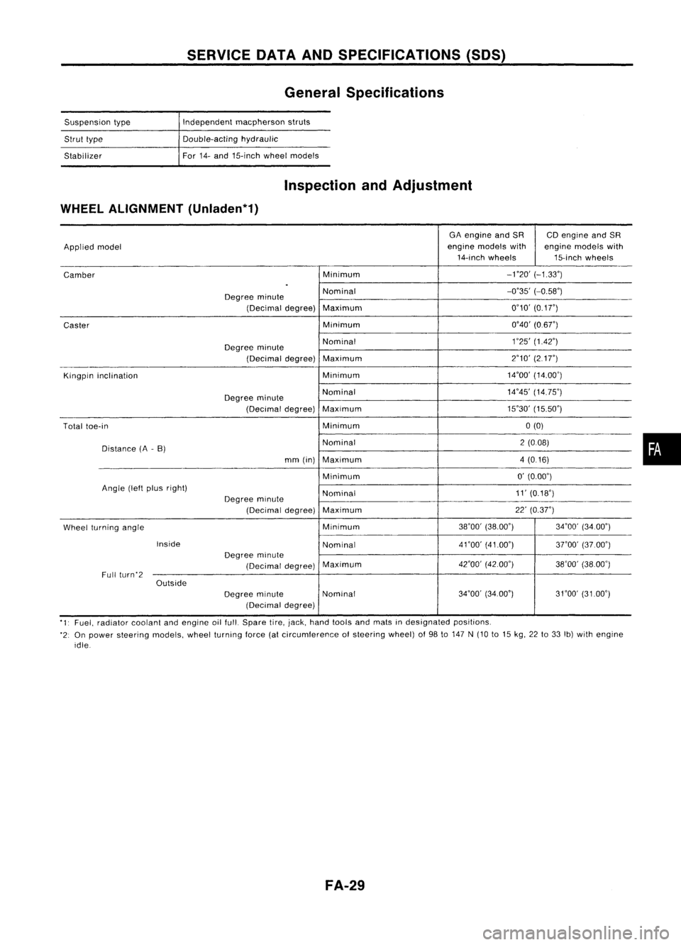
WHEEL ALIGNMENT (Unladen*1)
GAengine andSR CDengine andSR
Applied model engine
models with enginemodels with
14-inch wheels 15-inchwheels
Camber Minimum
-no'
(-1.33')
.
Degree minute Nominal
-0'35'
(-0.58')
(Decimal degree)Maximum 0'10'
(0.1
r)
Caster Minimum
0'40'(0.6r)
Degree minute Nominal
1
'25' (1.42')
(Decimal degree)Maximum 2'10'
(217")
Kingpin inclination Minimum14'00'
(14.00')
Degree minute Nominal
14'45'
(14.75')
(Decimal degree)Maximum 15'30'
(15.50')
Total toe-in Minimum0(0)
Distance (A-B) Nominal
2(008)
mm (in) Maximum 4(0.16)
Minimum 0'
(0.00')
Angle (leftplus right)
Nominal 11'
(0.18')
Degree minute
(Decimal degree)Maximum 22'
(0.37")
Wheel turning angle Minimum
38'00'
(38.00') 34'00'(34.00')
Inside Nominal4nO'
(41.00')
3rOO'(37.00')
Degree minute
(Decimal degree)Maximum
42'00'
(42.00')
38'00'(38.00')
Full (urn'2
Outside
Degreeminute Nominal 34'00'
(34.00') 31'00'(3100')
(Decimal degree)
'1' Fuel, radiator coolantandengine oilfull. Spare tire,jack, hand tools andmats indesignated positions.
'2: On power steering models,wheelturning force(atcircumference ofsteering wheel)of98 to147 N(10 to15 kg, 22to33 Ib)with engine
idle
FA-29
•
Page 1536 of 1701
0
0
•
0
0
~ /0
H
H
0
0
(2)
4wheels
5 wheels
SMA785C
Radial
tires
CHASSIS
ANDBODY MAINTENANCE
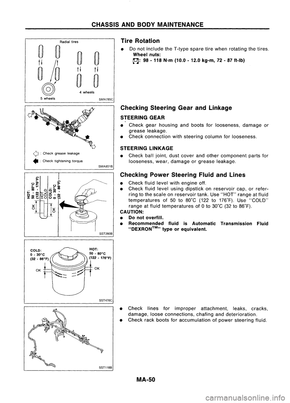
Tire Rotation
Do not include theT-type sparetirewhen rotating thetires .
Wheel nuts:
~: 98-118 N'm (10.0 -12.0 kg-m, 72-87 ft-Ib)
Q :
Check grease leakage
• :Check tightening torque
Checking
SteeringGearandLinkage
STEERING GEAR
• Check gearhousing andboots forlooseness, damageor
grease leakage.
• Check connection withsteering columnforlooseness.
STEERING LINKAGE
• Check balljoint, dustcover andother component partsfor
looseness, wear,damage orgrease leakage.
SMA851B
Checking PowerSteering FluidandLines
• Check fluidlevel withengine off.
• Check fluidlevel using dipstick onreservoir cap,orrefer-
ring tothe scale onreservoir tank.Use"HOT" rangeatfluid
temperatures of50 to80°C (122to176°F). Use"COLD"
range atfluid temperatures of
a
to 30°C (32to86°F).
CAUTION:
• Donot overfill.
• Recommended fluidisAutomatic Transmission Fluid
''DEXRON™,, typeorequivalent.
SST280B
SST476C
•Check linesforimproper attachment, leaks,cracks,
damage, looseconnections, chafinganddeterioration.
• Check rackboots foraccumulation ofpower steering fluid.
MA-50
Page 1620 of 1701
SERVICEDATAANDSPECIFICATIONS (50S)
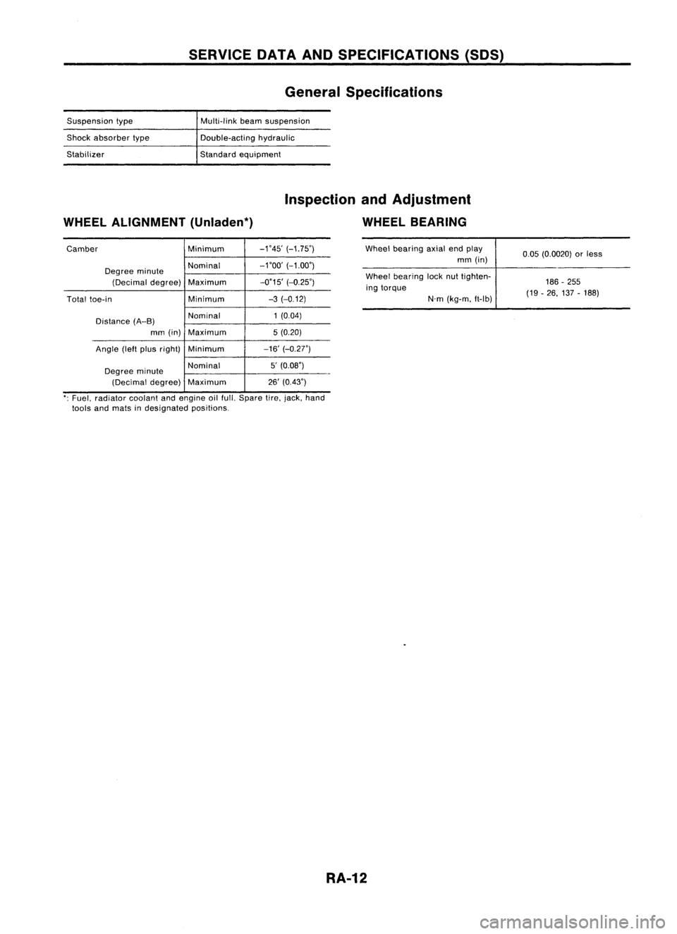
General Specifications
Suspension type
Shock absorber type
Stabilizer Multi-link
beamsuspension
Double-acting hydraulic
Standard equipment
WHEEL ALIGNMENT (Unladen*) Inspection
andAdjustment
WHEEL BEARING
Camber Minimum-1'45'
(-1.75')
Degree minute Nominal
-1'00'
(-1.00')
(Decimal degree) Maximum -0'15'
(-0.25')
Total toe-in Minimum-3
(-0.12)
Distance (A-B) Nominal
1
(0.04)
mm (in) Maximum 5(0.20)
Angle (leftpius right) Minimum -16'(-0.27')
Degree minute Nominal
5'
(0.08')
(Decimal degree)Maximum 26'
(0.43') Wheel
bearing axialendplay
mm (in)
Wheel bearing locknuttighten-
ing torque
N'm(kg-m. ft-lb) 0.05
(0.0020) orless
186 -255
(19 -26, 137 -188)
': Fuel, radiator coolantandengine oilfull. Spare tire.jack, hand
tools andmats indesignated positions.
RA-12
Page 1628 of 1701
SUPPLEMENTALRESTRAINTSYSTEM(SRS)
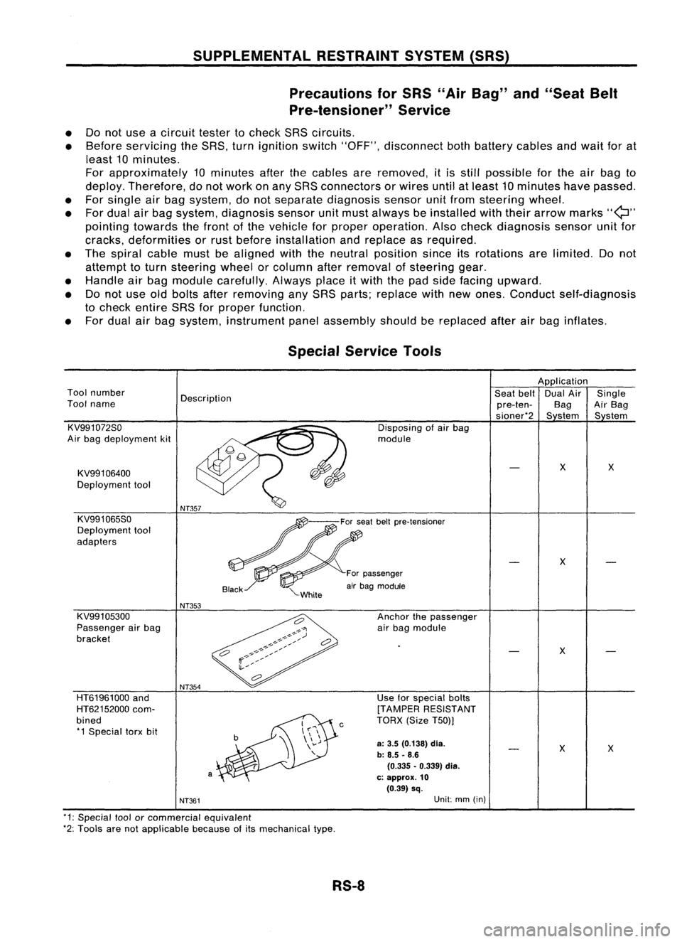
Precautions forSRS "AirBag" and"Seat Belt
Pre-tensioner" Service
• Donot use acircuit testertocheck SRScircuits.
• Before servicing theSRS. turnignition switch"OFF", disconnect bothbattery cablesandwait forat
least 10minutes.
For approximately 10minutes afterthecables areremoved, itis still possible forthe airbag to
deploy. Therefore, donot work onany SRS connectors orwires untilatleast 10minutes havepassed.
• For single airbag system, donot separate diagnosis sensorunitfrom steering wheel.
• For dual airbag system. diagnosis sensorunitmust always beinstalled withtheir arrow marks
"Q"
pointing towards thefront ofthe vehicle forproper operation. Alsocheck diagnosis sensorunitfor
cracks. deformities orrust before installation andreplace asrequired.
• The spiral cablemustbealigned withtheneutral position sinceitsrotations arelimited. Donot
attempt toturn steering wheelorcolumn afterremoval ofsteering gear.
• Handle airbag module carefully. Alwaysplaceitwith thepad side facing upward.
• Donot use oldbolts afterremoving anySRS parts; replace withnewones. Conduct self-diagnosis
to check entire SRSforproper function.
• For dual airbag system, instrument panelassembly shouldbereplaced afterairbag inflates.
X
X
Use
forspecial bolts
[TAMPER RESISTANT
TORX (SizeT50))
a:
3.5 (0.138)
dia.
b: 8.5 -8.6
(0.335 •0.339) dia.
c: approx.
10
(0.39) sq.
c
NT354
a
HT61961000
and
HT62152000 com-
bined *1 Special torxbit
Special
Service Tools
Application
Tool number
Description Seat
belt DualAir Single
Tool name
pre-ten-BagAirBag
sioner*2 Sstem Sstem
KV991072So Disposingofair bag
Air bag deployment kit module
KV991 06400
X
X
Deployment tool
KV991065So
Deployment tool
adapters
X
For passenger
air bag module
NT353
KV991 05300 Anchorthepassenger
Passenger airbag
airbag module
bracket
X
NT361
Unit:
mm(in)
*1: Special toolorcommercial equivalent
*2: Tools arenotapplicable becauseofits mechanical type.
RS-8
Page 1677 of 1701
STEERINGWHEELANDSTEERING COLUMN
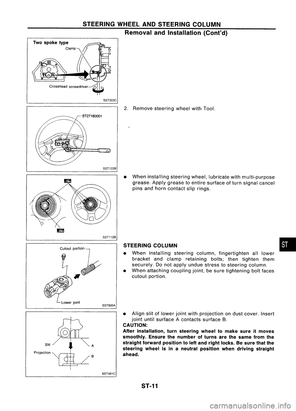
Removal andInstallation (Cont'd)
Two spoke type
Clamp
Crosshead screwdriver~
II
SST503C
2.Remove steering wheelwithTool.
SST122B
Cr~I~I;~
~#f
~.'".
Lowerjoint
SST112B
SST800A
•
When installing steeringwheel,lubricate withmulti-purpose
grease. Applygrease toentire surface ofturn signal cancel
pins andhorn contact sliprings.
STEERING COLUMN
• When installing steeringcolumn,fingertighten alllower
bracket andclamp retaining bolts;thentighten them
securely. Donot apply undue stress tosteering column.
• When attaching couplingjoint,besure tightening boltfaces
cutout portion.
• Align slitoflower jointwithprojection ondust cover. Insert
joint untilsurface Acontacts surfaceB.
CAUTION:
After installation, turnsteering wheeltomake sureitmoves
smoothly. Ensurethenumber ofturns arethesame fromthe
straight forward position toleft and right locks. Besure thatthe
steering wheelisin aneutral position whendriving straight
ahead.
•
SST491C ST-11