Page 253 of 1701
EXTERIOR
@
Front airspoiler
SEC. 960
8BT074
@
Front struttower barassembly
SEC. 401
[OJ:
N.m (kg-m, ft-lb)
8BT099
•
CAUTION:
Do not remove frontstruttower barassembly whilevehicle isjacked upwith wheels on.
8T-33
Page 686 of 1701
FRONTSUSPENSION SYSTEM
SEC. 391-400-401
When installing rubberparts,finaltightening mustbecarried outunder unladen condition" withtires onground .
• Fuel, radiator coolantandengine oilfull. Spare tire,jack, hand tools andmats indesignated positions.
~~25.29
~ (2.5•3.0, 18•22)
\ \
...
5
~ 98•118 (10•12, 72•87)
Front
to.J:
N. m (kg-m, ft-Ib)
SFA715B
CD
Suspension member
@
Stabilizer bar
@
Drive shaft
@
Coilspring
@
Strut assembly
@
Knuckle
FA-4
(J)
Transverse link
@
Front struttower bar
Page 709 of 1701

View
from
B FRONT
SUSPENSION
Stabilizer Bar(Cont'd)
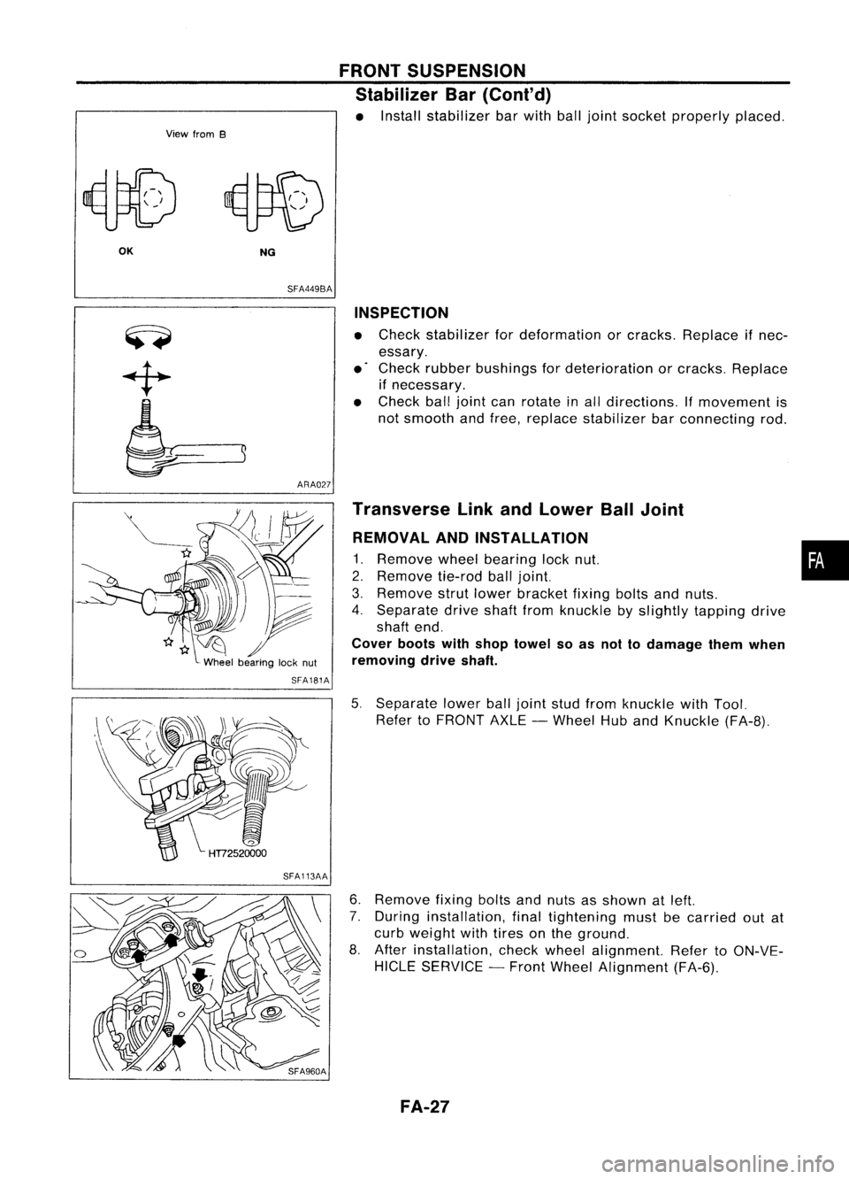
• Install stabilizer barwith balljoint socket properly placed.
OK NG
SFA449BA
ARA027 INSPECTION
• Check stabilizer fordeformation orcracks. Replace ifnec-
essary.
• Check rubber bushings fordeterioration orcracks. Replace
if necessary.
• Check balljoint canrotate inall directions. If
movement
is
not smooth andfree, replace stabilizer barconnecting rod.
SFA181A
SFA113AA Transverse
LinkandLower BallJoint
REMOVAL ANDINSTALLATION
1. Remove
wheelbearing locknut. •
2. Remove
tie-rodballjoint.
3. Remove
strutlower bracket fixingboltsandnuts.
4. Separate driveshaftfromknuckle byslightly tapping drive
shaft end.
Cover bootswithshop towel soas not todamage themwhen
removing driveshaft.
5. Separate lowerballjoint studfrom knuckle withTool.
Refer toFRONT AXLE-Wheel HubandKnuckle (FA-8).
6. Remove
fixingboltsandnuts asshown atleft.
7. During installation, finaltightening mustbecarried outat
curb weight withtires onthe ground.
8. After installation, checkwheel alignment. RefertoON-VE-
HICLE SERVICE -Front Wheel Alignment (FA-6).
FA-27
Page 1696 of 1701
POWERSTEERING OILPUMP
Pre-disassembly Inspection
Disassemble thepower steering oilpump onlyifthe following
items arefound.
• Oilleak from anypoint shown inthe figure
• Deformed ordamaged pulley
• Poor performance
SST984A Disassembly
CAUTION: • Parts which canbedisassembled arestrictly limited. Never
disassemble partsother thanthose specified.
• Disassemble inas clean aplace aspossible.
• Clean yourhands before disassembly.
• Donot use rags; usenylon cloths orpaper towels.
• Follow theprocedures andcautions inthe Service Manual.
• When disassembling andreassembling, donot letforeign
matter enterorcontact theparts.
Front housing Extension
bar
•
Remove snapring,thendraw drive shaftout.
Be careful nottodrop drive shaft.
SST010B
•Remove oilseal.
Be careful nottodamage fronthousing.
• Remove connector andflow control valvewithspring.
Be careful nottodrop flowcontrol valve.
SST036A 5T-30