Page 18 of 1701

SAT497GTROUBLE
DIAGNOSES
Road Testing (Cont'd)
"0"
POSITION
1. Manually moveselector leverfrom"N"to"D" position, and
note shiftquality.
2. Using theshift schedule asareference, drivevehicle in"D"
position. Record,onsymptom chart,respective vehicle
speeds atwhich up-shifting anddown-shifting occur.These
speeds aretobe read atthree different throttlepositions
(light, halfandfull), respectively. Alsodetermine thetiming
at which shocks areencountered duringshifting andwhich
clutches areengaged.
SAT612GA
3.Determine whetherlock-upproperly occurswhiledriving
vehicle inproper gearposition andatproper vehicle speed.
4. Check todetermine ifshifting tooverdrive gearcannot be
made whileODcontrol switchis"OFF".
5. Drive vehicle in"D
3"
position athalf tolight throttle posi-
tion. Keep driving at60 to70 km/h (34to43 MPH). FUlly
depress accelerator pedaltomake suretransaxle down-
shifts from3rdto2nd gear.
6. Drive vehicle in"D
2"
position athalf tolight throttle posi-
tion. Keep driving at25 to35 km/h (16to22 MPH). Fully
depress accelerator pedaltomake suretransaxle down-
shifts from2ndto1st gear.
"2"
POSITION
1. Shift to"2" position andmake surevehicle startsin1st
gear.
2. Increase vehiclespeedtomake suretransaxle upshiftsfrom
1st to2nd gear.
3. Further increase vehiclespeed.Makesuretransaxle does
not upshift to3rd gear.
4. Drive vehicle in"2
2"
position athalf tolight throttle position.
Keep driving at25 to35 km/h (16to22 MPH). Fullydepress
accelerator pedaltomake suretransaxle downshifts from
2nd to1st gear.
5. Allow vehicle torun idle while in"2" position tomake sure
that transaxle downshifts to1st gear.
6. Move selector leverto"D" position andallow vehicle to
operate at30 to40 km/h (19to25 MPH). Then,shiftto"2"
position tomake suretransaxle downshifts to2nd gear.
"1"
POSITION
1. Place selector leverin"1" position andaccelerate vehicle.
Make suretransaxle doesnotshift from 1stto2nd gear
although vehiclespeedincreases.
2. Drive vehicle in"1" position. Releaseaccelerator pedalto
make surethatengine compression actsasabrake.
3. Place selector leverin"D" or"2" position andallow vehi-
cle torun at15 to25 km/h (9to 16 MPH). Thenmove selec-
tor lever to"1" position tomake suretransaxle downshifts
to 1st gear.
AT-18
Page 24 of 1701
TROUBLEDIAGNOSES
Stall Tasting
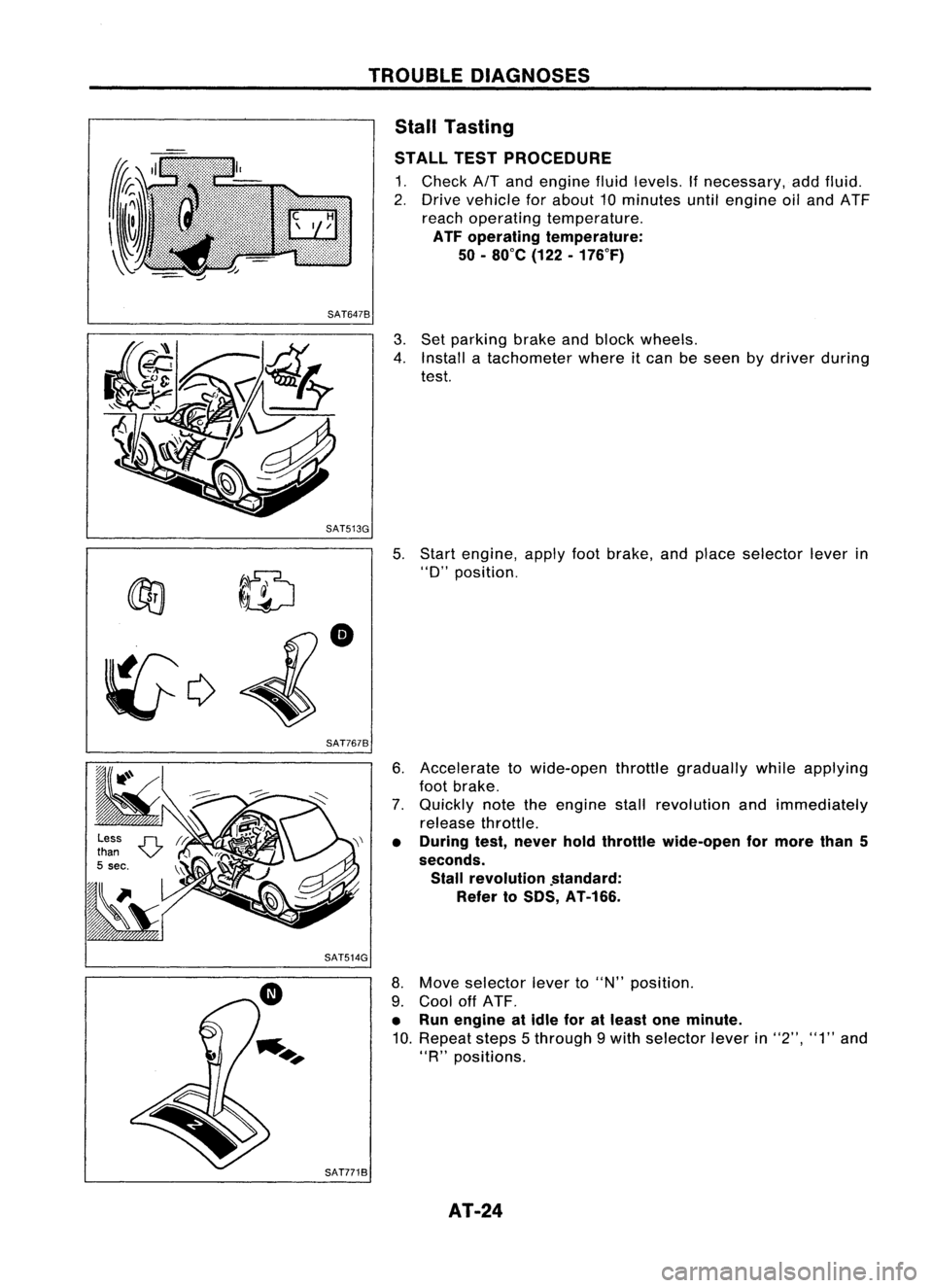
STALL TESTPROCEDURE
1. Check
AIT
and engine fluidlevels. Ifnecessary, addfluid.
2. Drive vehicle forabout 10minutes untilengine oiland ATF
reach operating temperature.
ATF operating temperature:
50 -80
0
e (122-176°F)
SAT6478
3.Set parking brakeandblock wheels.
4. Install atachometer whereitcan beseen bydriver during
test.
SAT513G 5.
~ ~ID
•
~c;>
SAT7678
Start
engine, applyfootbrake, andplace selector leverin
"0"
position.
6. Accelerate towide-open throttlegradually whileapplying
foot brake.
7. Quickly notetheengine stallrevolution andimmediately
release throttle.
• During test,never holdthrottle wide-open formore than5
seconds. Stall revolution .standard:
Refer toSDS, AT-166.
SAT514G
8.Move selector leverto"N" position.
9. Cool offATF.
• Run engine atidle foratleast oneminute.
10. Repeat steps5through 9with selector leverin"2", "1"and
"R
n
positions.
SAT7718 AT-24
Page 25 of 1701
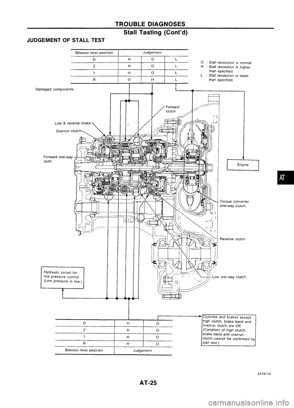
JUDGEMENT OFSTALL TEST
Selector leverposition
TROUBLE
DIAGNOSES
Stall Tasting (Cont'd)
Judgement
D
2
R
Damaged components
Forward one-way
cluth
Hydraulic circuitfor
line pressure control
(Line pressure islow.)
D
2
R
Selector leverposition H
H
H
o
H
H
H
H
o
o
o
H
o
o
o
o
Judgement
AT-25
L
L
L
L
o
:
Stall
revolution
isnormal.
H :Stall revolution ishigher
than specified.
L :Stall revolution islower
than specified.
Engine
Torque converter
one-way clutch
Reverse clutch
Low one-way clutch
Clutches andbrakes except
high clutch, brakebandand
overrun clutchareOK.
(Condition ofhigh clutch,
brake bandandoverrun
clutch cannot beconfirmed by
stall test.)
SAT871H
•
Page 26 of 1701
TROUBLEDIAGNOSES
Pressure Testing
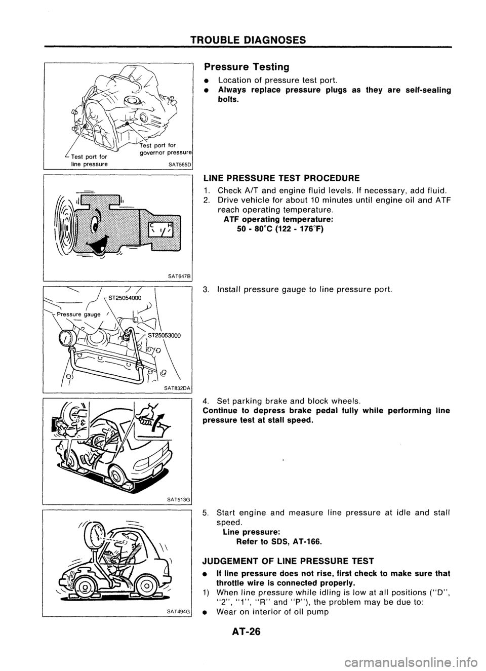
• Location ofpressure testport.
• Always replace pressure plugsasthey areself-sealing
bolts.
Test portfor
line pressure governor
pressure
SAT565D
LINEPRESSURE TESTPROCEDURE
1. Check AfTand engine fluidlevels. Ifnecessary, addfluid.
2. Drive vehicle forabout 10minutes untilengine oiland ATF
reach operating temperature.
ATF operating temperature:
50 -80°C (122-176°F)
SAT647B
3.Install pressure gaugetoline pressure port.
4. Set parking brakeandblock wheels.
Continue todepress brakepedalfullywhile performing line
pressure testatstall speed.
SAT513G
5.Start engine andmeasure linepressure atidle and stall
speed. Line pressure:
Refer toSOS, AT-166.
JUDGEMENT OFLINE PRESSURE TEST
• Ifline pressure doesnotrise, firstcheck tomake surethat
throttle wireisconnected properly.
1) When linepressure whileidling
is
low atall positions ("D",
"2", "1", "R"and"P"), theproblem maybedue to:
SAT494G •
Wear oninterior ofoil pump
AT-26
Page 27 of 1701
'-)
(
~)o
Front
SAT498GTROUBLE
DIAGNOSES
Pressure Testing(Cont'd)
• Oilleakage ator around oilpump, control valvebody, trans-
mission caseorgovernor
• Sticking pressure regulator valve
• Sticking pressure modifiervalve
2) When linepressure whileidling islow ataparticular
position, checkthefollowing.
• Ifoil leaks ator around low
&
reverse brakecircuit, line
pressure becomes lowin"R" position. Butline pressure is
normal in"P", "D", "2"or"1" position.
3) When linepressure ishigh while idling, pressure regulator
valve mayhave stuck.
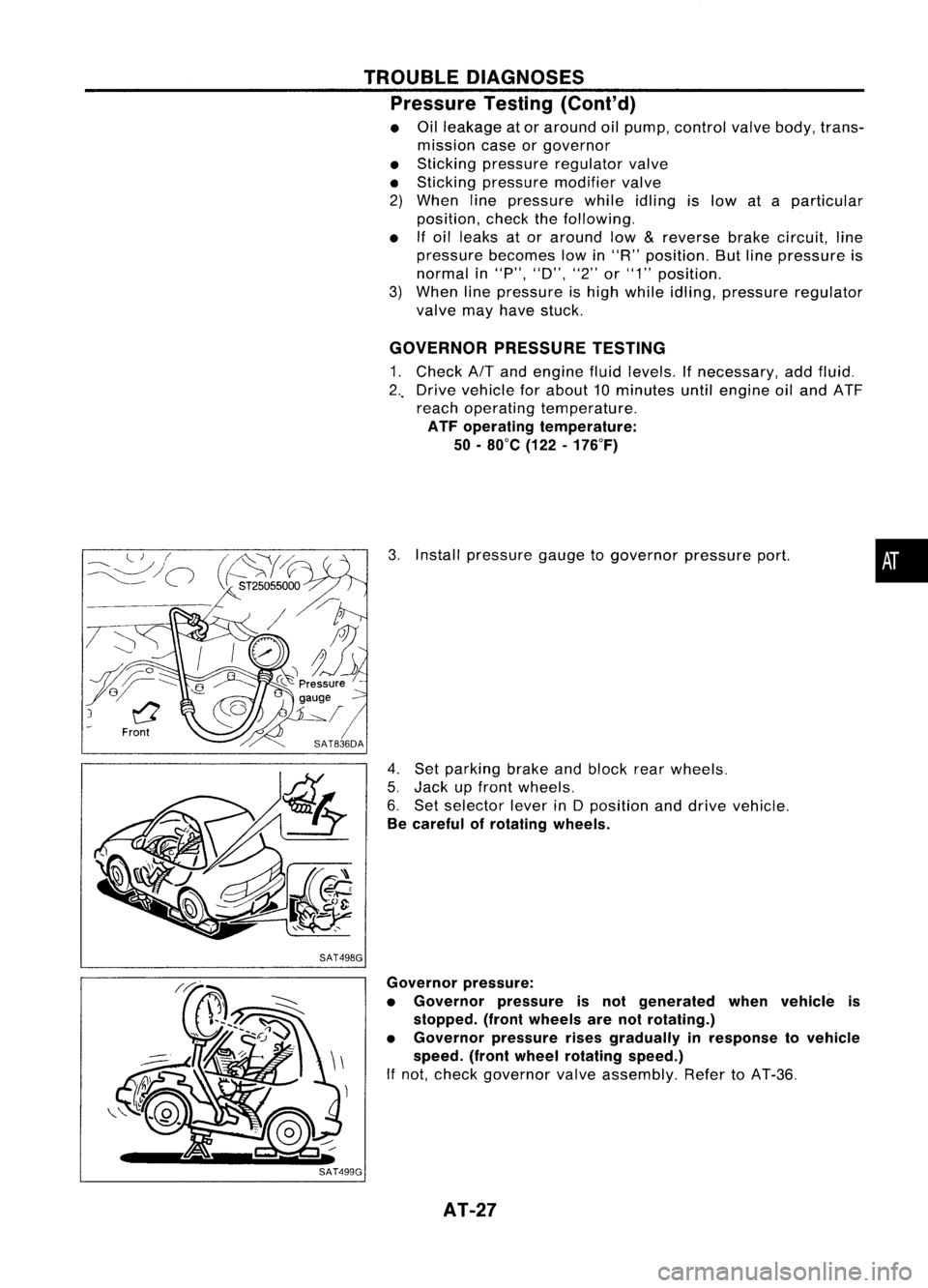
GOVERNOR PRESSURETESTING
1. Check
AIT
and engine fluidlevels. Ifnecessary, addfluid.
2 .. Drive vehicle forabout 10minutes untilengine oiland ATF
reach operating temperature.
ATF operating temperature:
50 -80°C (122-176°F)
3. Install pressure gaugetogovernor pressureport.
4. Set parking brakeandblock rearwheels.
5. Jack upfront wheels.
6. Set selector leverinDposition anddrive vehicle.
Be careful ofrotating wheels.
•
Governor pressure:
• Governor pressureisnot generated whenvehicle is
stopped. (frontwheels arenotrotating.)
• Governor pressurerisesgradually inresponse tovehicle
speed. (frontwheel rotating speed.)
If not, check governor valveassembly. RefertoAT-36.
AT-27
Page 41 of 1701
Boltlength
'T'
mm (in)
55 (2.17)
50 (1.97)
65 (2.56)
25 (0.98)
40 (1.57)
Tightening
torque
N'm (kg-m, ft-Ib)
70 -79 (7.1 -8.1,51 -59)
70 -79 (7.1 -8.1, 51-59)
70 -79 (7.1 -8.1,51 -59)
30 -40 (3.1 -4.1, 22-30)
30 -40 (3.1 -4.1, 22-30)
CD
@
@
@
@
Bolt
No.
• Reinstall anypart removed.
• Adjust throttle wireandcontrol cable.Referto"ON-VEHI-
CLE SERVICE", AT-33,35.
•. Check inhibitor switch.Referto"Electrical Components
Inspection", AT-3D.
• Refill transaxle withATFandcheck fluidlevel, AT-17.
• Move selector leverthrough allpositions tobe sure that
transaxle operatescorrectly. Withparking brakeapplied,
idle engine. Moreselector leverthrough "N"to"D", to"2",
to "1" and "R". Aslight shock should befelt through the
hand gripping theselector eachtimethetransaxle is
shifted. •
• Perform roadtest-Refer to"ROAD TESTING", AT-17.
i
REMOVAL
ANDINSTAllATION
Installation (Cont'd)
SR engine models
SAT638A
SAT558DA
AIT
toengine
@
Engine to
AIT
AT-41
Page 47 of 1701
MAJOROVERHAUL
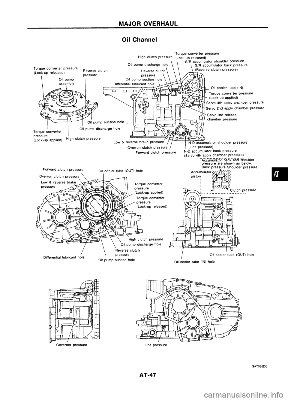
Oil Channel
High clutch pressure
Oilcooler tube(OUT) hole
•
Oil
cooler tube
(IN)
Torque converter pressure
(Lock-up applied)
" Servo
4th
apply chamber pressure
Servo 2ndapply chamber pressure
• Servo 3rdrelease
chamber pressure
Torque
converter pressure
(Lock-up released)
SIR accumulator shoulderpressure
SIR accumulator backpressure
(Reverse clutchpressure)
Oil cooler tube
(IN)
hole
Torque
converter
pressure (Lock-up applied)
Torque converter
pressure (Lock-up released)
reverse
brakepressure
Overrun clutchpressure
Forward clutchpressure
High
clutch pressure
Reverse clutch
pressure
Oil pump suction hole
Differential lubricanthole
High clutch pressure
Oil pump discharge hole
Reverse clutch
pressure
Oil pump suction hole
Reverse
clutch
pressure
Low
&
Oil
pump suction hole
Oil pump discharge hole
Forward clutchpressure
Overrun clutchpressure
Low
&
reverse brake
pressure
Torque
converter pressure
(Lock-up released)
Torque converter
pressure (Lock-up applied)
Governor pressure
Linepressure
SAT586DC
AT-47
Page 57 of 1701
l~~
.
_~
Unit:mm(in)
SAT039D DISASSEMBLY
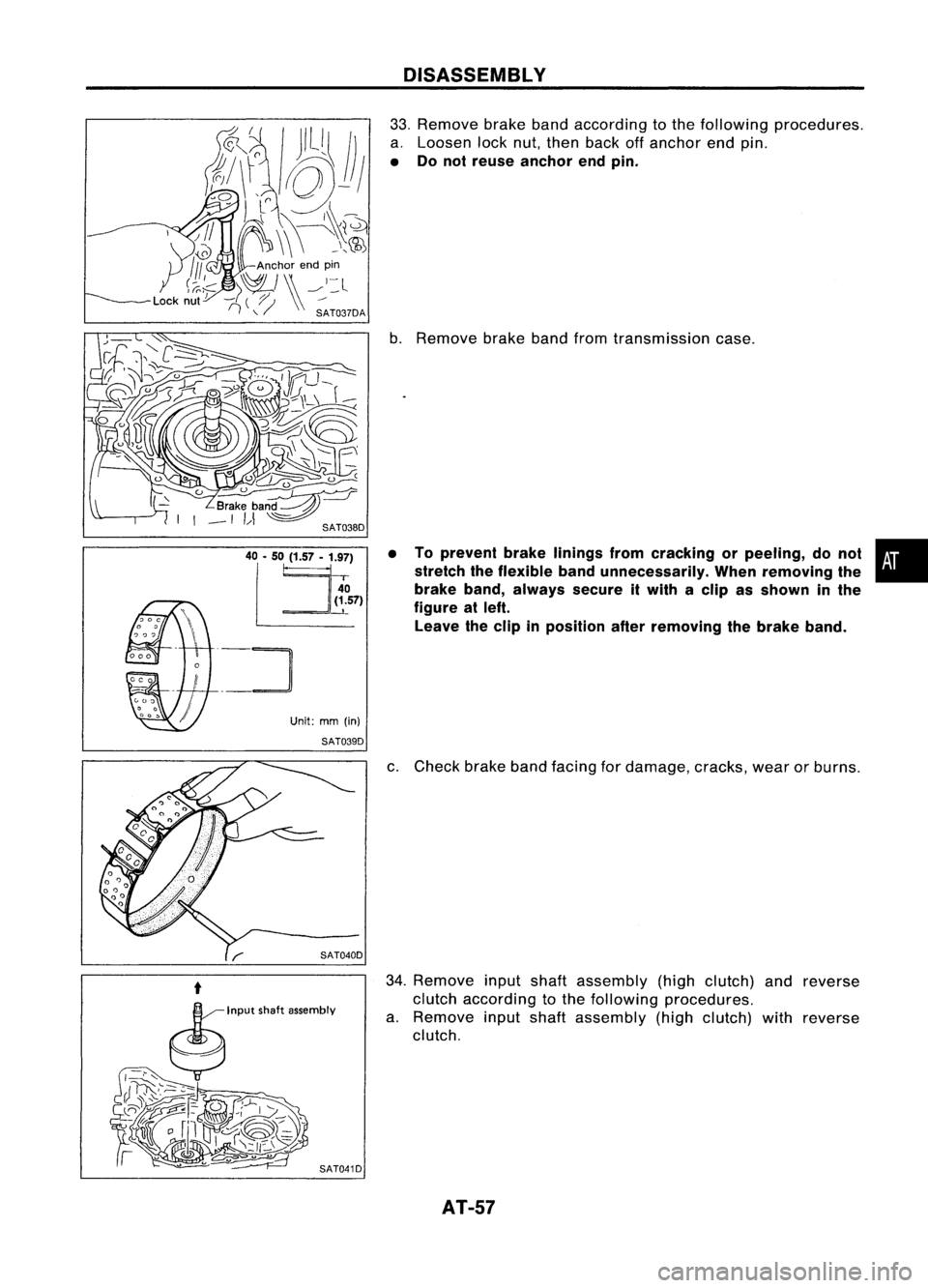
33. Remove brakebandaccording tothe following procedures.
a. Loosen locknut,then back offanchor endpin.
• Donot reuse anchor endpin.
b. Remove brakebandfromtransmission case.
• Toprevent brakelinings fromcracking orpeeling, donot •
stretch theflexible bandunnecessarily. Whenremoving the
i
brake band,always secureitwith aclip asshown inthe
figure atleft.
Leave theclip inposition afterremoving thebrake band.
c. Check brakebandfacing fordamage, cracks,wearorburns.
34. Remove inputshaftassembly (highclutch) andreverse
clutch according tothe following procedures.
a. Remove inputshaft assembly (highclutch) withreverse
clutch.
AT-57