1995 NISSAN ALMERA N15 Timing marks
[x] Cancel search: Timing marksPage 771 of 1701
![NISSAN ALMERA N15 1995 Service Manual ON-BOARDDIAGNOSTIC SYSTEMDESCRIPTION
CONSULT (Coni'd)
Monitored item
ECM
Main
[Unit] input
signals Description
Remarks
signals
LOAD SIGNAL •Indicates [ON/OFF] conditionfromthe
[ON/OFF] reardefo](/manual-img/5/57349/w960_57349-770.png "NISSAN ALMERA N15 1995 Service Manual ON-BOARDDIAGNOSTIC SYSTEMDESCRIPTION
CONSULT (Coni'd)
Monitored item
ECM
Main
[Unit] input
signals Description
Remarks
signals
LOAD SIGNAL •Indicates [ON/OFF] conditionfromthe
[ON/OFF] reardefo")
ON-BOARDDIAGNOSTIC SYSTEMDESCRIPTION
CONSULT (Coni'd)
Monitored item
ECM
Main
[Unit] input
signals Description
Remarks
signals
LOAD SIGNAL •Indicates [ON/OFF] conditionfromthe
[ON/OFF] reardefogger signaland/or lighting
switch.
0 0
ON:
Rear defogger isoperating
and/or lighting switchison.
OFF: Rear defogger isnot operating
and lighting switchisnot on.
INJ PULSE [msec]
0
•
Indicates theactual fuelinjection
•When theengine isstopped, acertain
pulse widthcompensated byECM computedvalueisindicated.
according tothe input signals.
IGN TIMING [BTDC]
0
•
Indicates theignition timingcomputed
by ECM according tothe input sig-
nals.
IACV-AACIV
[%]
•Indicates theidle aircontrol valve
0
(AAC
valve) control valuecomputed
by ECM according tothe input sig-
nals.
A/F ALPHA
[%]
•Indicates themean valueofthe air-
•When theengine isstopped, acertain
0
fuel
ratio feedback correction factor valueisindicated.
per cycle. •This data alsoincludes thedata for
the air-fuel ratiolearning control.
AIR COND RLY
0
•
Indicates theairconditioner relay
[ON/OFF] controlcondition (determined byECM
according tothe input signal).
COOLING FAN*2
•Indicates thecontrol condition ofthe
[ON/OFF] or[LOW/
coolingfans(determined byECM
HI/OFF]
0
according
tothe input signal).
ON ...Operating
LOW ...Operates atlow speed
HI ...Operates athigh speed
OFF ...Stopped
FUEL PUMP RLY
0
•
Indicates thefuel pump relaycontrol
[ON/OFF] conditiondetermined byECM accord-
ing tothe input signals.
VALVE TIMSOL*1
•The control condition ofthe valve tim-
[ON/OFF] ingsolenoid valve(determined by
ECM according tothe input signal) is
indicated.
ON ...VTC operating
OFF ...VTC notoperating
EGRC SOLIV (EVAP
•Indicates thecontrol condition ofthe
canister purgecon-
EVAPcanister purgecontrol solenoid
trol solenoid valve valveorEGR valve
&
EVAP canister
or EGR
&
EVAP can- purgecontrol solenoid valve(deter-
ister purge control
0
mined
byECM according tothe input
solenoid valve) signal).
[ON/OFF] ON'"EVAP canister purgeoperation
cut-off OFF ...EVAP canister purgeoperation
not cut-off
VOLTAGE •Voltage measured bythe voltage
[V] probe.
PULSE •Pulse width, frequency orduty cycle •Only "#"isdisplayed ifitem is
[msec] or[Hz] or measuredbythe pulse probe. unable
tobe measured .
[%]
•
Figures with"#"s aretemporary
ones. Theyarethesame figures as
an actual pieceofdata which wasjust
previously measured.
*1: GA16DE exceptforEurope andIsrael
*2: GA16DE engineA/Tmodels forEurope without heavydutykithave a2- step control [ON/OFF] system."LOW"and"HI"
are shown onCONSULT screentorepresent "ON"condition.
EC-52
Page 793 of 1701
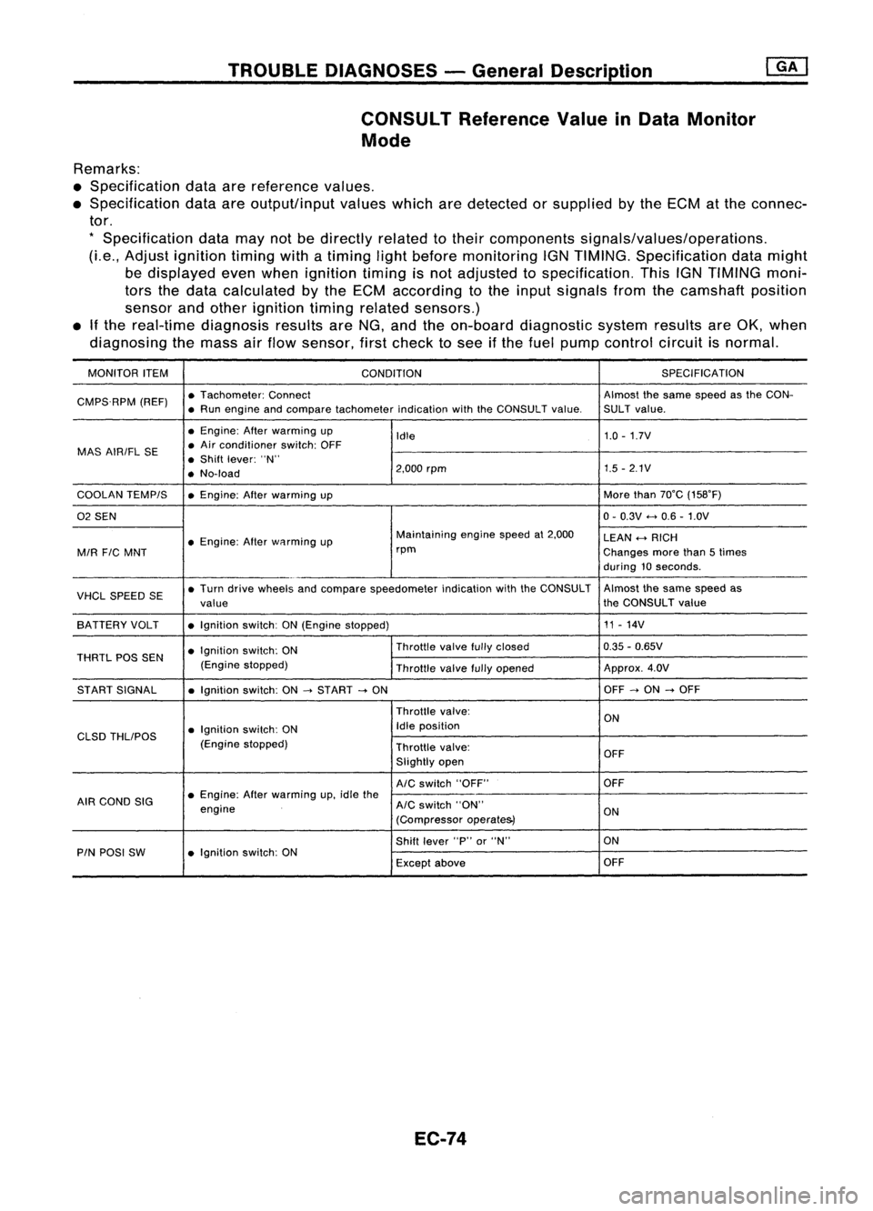
TROUBLEDIAGNOSES -General Description
CONSULT ReferenceValueinData Monitor
Mode
Remarks:
• Specification dataarereference values.
• Specification dataareoutput/input valueswhicharedetected orsupplied bythe ECM atthe connec-
tor.
*
Specification datamaynotbedirectly relatedtotheir components signals/values/operations.
(Le., Adjust ignition timingwithatiming lightbefore monitoring IGNTIMING. Specification datamight
be displayed evenwhen ignition timingisnot adjusted tospecification. ThisIGNTIMING moni-
tors thedata calculated bythe ECM according tothe input signals fromthecamshaft position
sensor andother ignition timingrelated sensors.)
• Ifthe real-time diagnosis resultsareNG, and theon-board diagnostic systemresultsareOK, when
diagnosing themass airflow sensor, firstcheck tosee ifthe fuel pump control circuitisnormal.
MONITOR ITEM
CONDITION SPEC
IFICA TION
CMPS.RPM (REF)•
Tachometer: Connect Almostthesame speed asthe CON-
• Run engine andcompare tachometer indicationwiththeCONSULT value.SULT value.
• Engine: Afterwarming up
Idle 1.0
-1.7V
MAS AIRIFL SE •
Air conditioner switch:OFF
• Shift lever: "N"
• No-load 2,000
rpm 1.5
-2.1V
COOLAN TEMPIS •Engine: Afterwarming up More
than70°C (158°F)
02 SEN 0-
0.3V
<-+
0.6 -1.0V
• Engine: Afterwflrming up Maintaining
enginespeedat2,000
LEAN
<-+
RICH
MIR
FIC
MNT rpm
Changesmorethan5times
during 10seconds .
VHCL SPEED SE•
Turn drive wheels andcompare speedometer indicationwiththeCONSULT Almost
thesame speed as
value the
CONSULT value
SA TTERY VOLT •Ignition switch:ON(Engine stopped) 11
-14V
• Ignition switch:ON Throttle
valvefullyclosed 0.35
-0.65V
THRTL POSSEN
(Enginestopped)
Throttlevalvefullyopened Approx.
4.0V
ST ART SIGNAL •Ignition switch:ON
-->
START
-->
ON OFF
-->
ON
-->
OFF
Throttle valve:
ON
• Ignition switch:ON Idle
position
CLSD THLIPOS
(Enginestopped)
Throttlevalve:
OFF
Slightly open
AIC
switch "OFF" OFF
AIR COND SIG •
Engine: Afterwarming up,idle the
engine
AIC
switch "ON"
ON
(Compressor operate&)
Shift lever "P"or"N" ON
PIN POSI SW •Ignition switch:ON
Exceptabove OFF
EC-74
Page 977 of 1701
![NISSAN ALMERA N15 1995 Service Manual ON-BOARDDIAGNOSTIC SYSTEMDESCRIPTION
CONSULT (Conl'd)
Monitored item ECM
Main
[Unit] input
signals Description
Remarks
signals
AIR COND SIG •Indicates [ON/OFF] conditionofthe
[ON/OFF]
00
air](/manual-img/5/57349/w960_57349-976.png "NISSAN ALMERA N15 1995 Service Manual ON-BOARDDIAGNOSTIC SYSTEMDESCRIPTION
CONSULT (Conl'd)
Monitored item ECM
Main
[Unit] input
signals Description
Remarks
signals
AIR COND SIG •Indicates [ON/OFF] conditionofthe
[ON/OFF]
00
air")
ON-BOARDDIAGNOSTIC SYSTEMDESCRIPTION
CONSULT (Conl'd)
Monitored item ECM
Main
[Unit] input
signals Description
Remarks
signals
AIR COND SIG •Indicates [ON/OFF] conditionofthe
[ON/OFF]
00
air
conditioner switchasdetermined
by the airconditioning signal.
PIN POSI SW
00
•
Indicates [ON/OFF] conditionfromthe
[ON/OFF] park/neutralpositionswitchsignal.
PW/ST SIGNAL •Indicates [ON/OFF] conditionofthe
[ON/OFF]
00
power
steering oilpressure switch
determined bythe power steering oil
pressure signal.
INJ PULSE [msec]
0
•
Indicates theactual fuelinjection •
When theengine isstopped, acertain
pulse widthcompensated byECM computedvalueisindicated.
according tothe input signals.
IGN TIMING [BTDC]
0
•
Indicates theignition timingcomputed
by ECM according tothe input sig-
nals.
IACV-AACIV
[%]
•Indicates theidle aircontrol valve
0
(AAC
valve) control valuecomputed
by ECM according tothe input sig-
nals.
A/F ALPHA [%J •Indicates themean valueofthe air- •When theengine isstopped, acertain
0
fuel
ratio feedback correction factor valueisindicated.
per cycle. •This dataalsoincludes thedata for
the air-fuel ratiolearning control.
AIR COND RLY •Indicates theairconditioner relay
[ON/OFF]
0
control
condition (determined byECM
according tothe input signal).
FUEL PUMP RLY •Indicates thefuel pump relaycontrol
[ON/OFFJ
0
condition
determined byECM accord-
ing tothe input signals.
COOLING FAN
•Indicates thecontrol condition ofthe
[HI/LOW/OFFJ coolingfans(determined byECM
0
according
tothe input signal).
HI ...High speed operation
LOW ...Low speed operation
OFF ...Stopped
EGRC SOLIV •Indicates thecontrol condition ofthe
[ON/OFFJ EGR
valve
&
EVAP canister Purge
control solenoid valve(determined by
0
ECM
according tothe input signal).
ON ...EGR andEVAP canister purge
operation cut-off
OFF ...EGR andEVAP canister purge
operation notcut-off
VOLTAGE •Voltage measured bythe voltage
[V] probe.
PULSE •Pulse width, frequency orduty cycle •Only "#"isdisplayed ifitem is
[msec] or[Hz] or
measuredbythe pulse probe. unabletobe measured.
[%]
•Figures with"#"s aretemporary
ones. Theyarethesame figures as
an actual pieceofdata which wasjust
previously measured.
EC-258
Page 996 of 1701
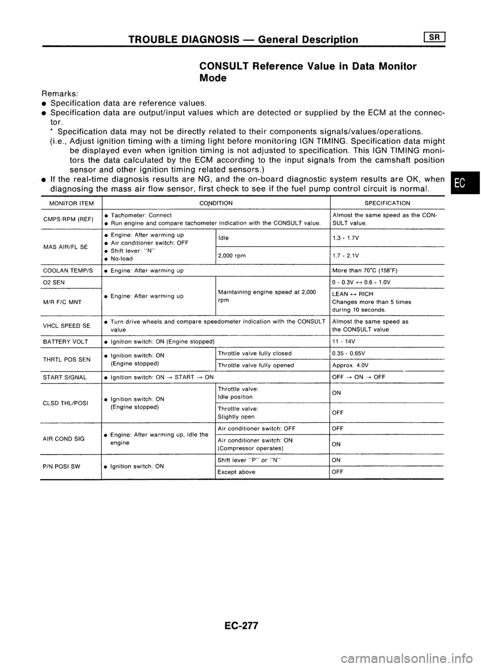
TROUBLEDIAGNOSIS -General Description
CONSULT Reference ValueinData Monitor
Mode
Remarks:
• Specification dataarereference values.
• Specification dataareoutput/input valueswhicharedetected orsupplied bythe ECM atthe connec-
tor.
*
Specification datamaynotbedirectly relatedtotheir components signals/values/operations.
(Le., Adjust ignition timingwithatiming lightbefore monitoring IGNTIMING. Specification datamight
be displayed evenwhen ignition timingisnot adjusted tospecification. ThisIGNTIMING moni-
tors thedata calculated bythe ECM according tothe input signals fromthecamshaft position
sensor andother ignition timingrelated sensors.)
• Ifthe real-time diagnosis resultsareNG, andtheon-board diagnostic systemresultsareOK, when •
diagnosing themass airflow sensor, firstcheck tosee ifthe fuel pump control circuitisnormal.
MONITOR ITEM CONDITION
SPECIFICATION
CMPS.RPM (REF)•
Tachometer: Connect Almostthesame speed asthe CON-
• Run engine andcompare tachometer indicationwiththeCONSULT value.SULTvalue.
• Engine: Afterwarming up
Idle 1.3-1.7V
MAS AIR/FL SE •
Air conditioner switch:OFF
• Shift lever: "N"
• No-load 2,000
rpm 1.7-2.1V
COOLAN TEMPIS •
Engine: Afterwarming up More
than70°C (15S0F)
02 SEN 0-
0.3V .....0.6 -1.0V
• Engine: Afterwarming up Maintaining
enginespeedat2,000
LEAN
+-->
RICH
MIR
FIC
MNT rpm
Changesmorethan5times
during 10seconds.
VHCL SPEED SE•
Turn drive wheels andcompare speedometer indicationwiththeCONSULT Almostthesame speed as
value the
CONSULT value
BATTERY VOLT •
Ignition switch:ON(Engine stopped) 11
-14V
• Ignition switch:ON Throttle
valvefullyclosed
0.35-0.65V
THRTL
pas
SEN
(Enginestopped)
Throttlevalvefullyopened Approx.4.0V
START SIGNAL •
Ignition switch:ON
->
START
->
ON OFF
->
ON
->
OFF
Throttle valve:
ON
• Ignition switch:ON Idle
position
CLSD THLIPOSI
(Enginestopped)
Throttlevalve:
Slightly open OFF
Air conditioner switch:OFF OFF
AIR COND SIG •
Engine: Afterwarming up,idle the
engine Air
conditioner switch:ON
ON
(Compressor operates)
Shift lever "P"or"N" ON
PIN POSI SW •
Ignition switch:ON
Exceptabove OFF
EC-277
Page 1092 of 1701
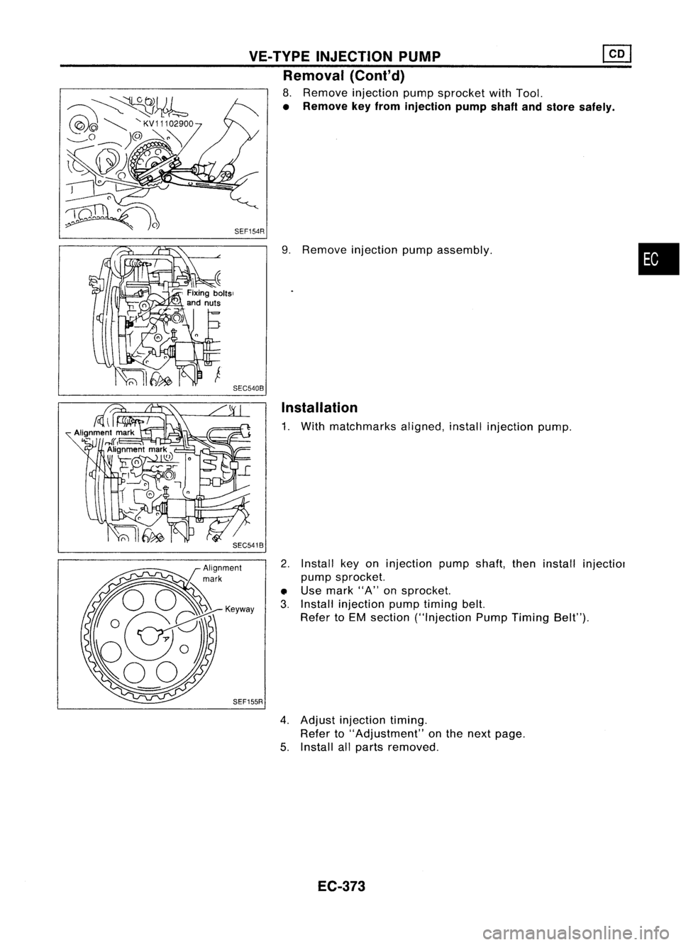
VE-TVPEINJECTION PUMP ~
Removal (Cont'd)
8. Remove injection pumpsprocket withTool.
• Remove keyfrom injection pumpshaftandstore safely .
9. Remove injection pumpassembly.
Installation
1. With matchmarks aligned,installinjection pump.
2. Install keyoninjection pumpshaft,theninstall injectiol
pump sprocket.
• Use mark "A"onsprocket.
3. Install injection pumptiming belt.
Refer toEM section ("Injection PumpTiming Belt").
SEF155R
4.Adjust injection timing.
Refer to"Adjustment" onthe next page.
5. Install allparts removed.
EC-373
•
Page 1202 of 1701
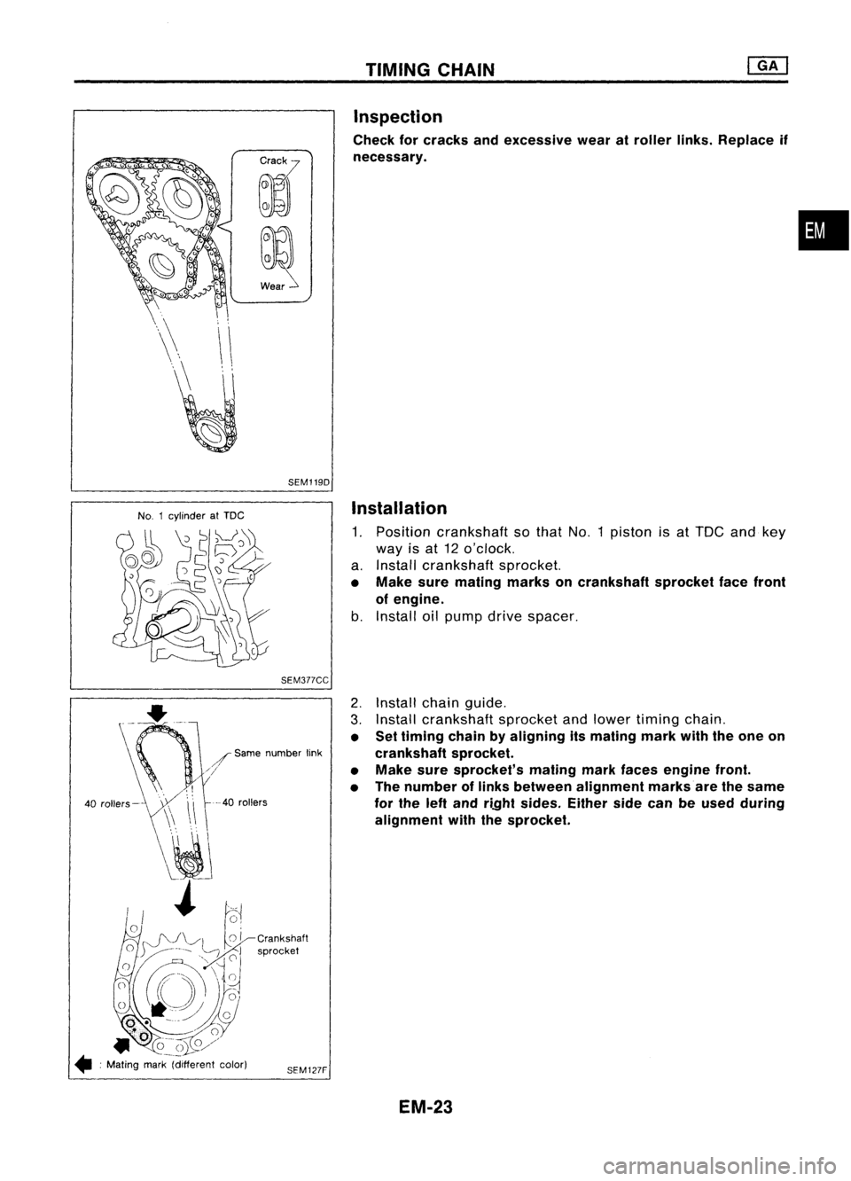
TIMINGCHAIN
Inspection
Check forcracks andexcessive wearatroller links.Replace if
necessary.
•
SEM1190
No. 1cylinder atTDC
Installation
1. Position crankshaft sothat No.1piston isat TOC andkey
way isat 12 o'clock.
a. Install crankshaft sprocket.
• Make suremating marksoncrankshaft sprocketfacefront
of engine.
b. Install oilpump drivespacer.
SEM377CC
--40
rollers
2.
Install chainguide.
3. Install crankshaft sprocketandlower timing chain.
• Settiming chainbyaligning itsmating markwiththeone on
crankshaft sprocket.
• Make suresprocket's matingmarkfaces engine front.
• The number oflinks between alignment marksare thesame
for the leftand ri.Qht sides. Eithersidecanbeused during
alignment withthesprocket.
SEM127F
/
Same number link
///
40 rollers-
• :Mating mark(different color)
EM-23
Page 1203 of 1701
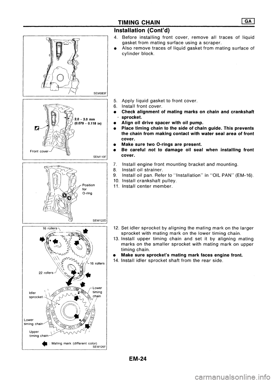
TIMINGCHAIN ~
Installation (Cont'd)
4. Before installing frontcover, remove alltraces ofliquid
gasket frommating surface usingascraper.
• Also remove tracesofliquid gasket frommating surface of
cylinder block.
5. Apply liquidgasket tofront cover.
6. Install frontcover.
• Check alignment ofmating marksonchain andcrankshaft
sprocket.
• Align oildrive spacer withoilpump.
• Place timing chaintothe side ofchain guide. Thisprevents
the chain frommaking contact withwater sealarea offront
cover.
• Make suretwoO-rings arepresent.
• Be careful nottodamage oilseal when installing front
cover.
7. Install engine frontmounting bracketandmounting.
8. Install oilstrainer.
9. Install oilpan. Refer to"Installation" in"OIL PAN" (EM-16).
10. Install crankshaft pulley.
11. Install center member.
12. Set idler sprocket byaligning themating markonthe larger
sprocket withmating markonthe lower timing chain.
13. Install uppertiming chainandsetitby aligning mating
marks onthe smaller sprocket withmating markonupper
timing chain.
• Make suresprocket's matingmarkfaces engine front.
14. Install idlersprocket shaftfromtherear side.
SEM083F
SEM110F
SEM122D
Position
for
O-ring
Front
cover
Upper timing chain
•. Mating mark(different color)
SEM126F
Idler
sprocket
Lower
timing chain
EM-24
Page 1205 of 1701

• Identification marksarepresent on")
Intakeside
o~ ~
~NO.5~
~ ~No. 4~
~ "'DNo. 3"~
L
"\J;;\
No.2
~V~NO'
~~FronOt mark~
Front ......., TIMING
CHAIN
Installation (Cont'd)
• Identification marksarepresent oncamshafts.
18. Install camshaft bracketsanddistributor bracket.
• Make surecamshaft bracketsarealigned asshown infig-
ure.
Exhaust side
SEM549D
Distributor bracket
I~
Apply liquidgasket.
@
@
@
rl~FL~~I~~~~
),i
o)(oo~-.'.-
0l1..0)(
0
~ .@/~
o'(!l@
@
cID
CD~cID
oc1)
1
0
@
Tighten innumerical order.
SEM550D
•
Apply liquidgasket todistributor bracketasshown inthe
figure.
• Apply newengine oiltobolt threads andseat surface.
• Tighten camshaft bracketboltsinthe following steps.
(Bolt
@>
isapplied onlyforGA16DE)
@
Tighten bolts
@-
@>,
then
CD-
@).
~: 2.0N'm (0.204 kg-m,17.7in-Ib)
@
Tighten bolts
CD-
@>.
~: 5.9N'm (0.60 kg-m, 52.1in-Ib)
@
Tighten bolts
CD-
@.
~: 9.8-11.8 N'm (1.00 -1.20 kg-m, 86.8-104.2 in-Ib)
Tighten bolt
@>.
~: 6.3-8.3 N'm (0.64 -0.85 kg-m, 55.6-73.8 in-Ib)
• Ifany part ofvalve assembly orcamshaft isreplaced, check
valve clearance accordingtoreference data.
After completing assemblycheckvalveclearance. Referto
"Checking" and"Adjusting" in"VALVE CLEARANCE" (EM-
41).
Reference datavalve clearance (Cold):
Intake
0.25 -0.33 mm(0.010 -0.013 in)
Exhaust
0.32 -0.40 mm(0.013 -0.016 in)
EM-26